
Abstract
Single cells based on Ni-CeO2-WC-YSZ anodes were investigated as an alternative material for direct methane solid oxide fuel cells. First, a YSZ electrolyte-based cell with porous YSZ as the support for electrode materials on both sides was prepared. Then electrocatalyst materials were incorporated into the porous YSZ: the anode was infiltrated with WC (25 vol.%), Ni (5 wt%) and ceria (5 wt%) precursors; and the cathode with LSM (20 vol.%) precursor. A Ni-CeO2-WC-YSZ symmetrical cell study showed that the Ni modified electrode performed stably with humidified methane at 850°C for a period of 48 hours under open circuit condition; no carbon formation was observed either with in-situ impedance spectroscopy or ex-situ scanning electron microscopy. Furthermore, the fuel cell results revealed that not only does the anode operate steadily with a reasonable performance on methane fuel, but the stability of the carbide phase is well maintained. The cell also successfully survived an oxidation-reduction-recarburization cycle. It was demonstrated that with a proper cell configuration, the structural integrity can be protected. These results suggest that a Ni modified anode is compatible with methane fuel, with reasonable and stable performance.
Export citation and abstract BibTeX RIS
Fuel flexibility and use of existing fuel infrastructure to bridge the hydrogen availability gap is perhaps the most important advantage of solid oxide fuel cells (SOFCs). In principle, an SOFC can operate on any combustible fuel such as hydrocarbons; as a matter of fact, direct utilization of hydrocarbons could facilitate commercialization of SOFCs and improve their efficiency. In practice, however, exploiting such great benefit is yet to be accomplished mainly due to the incompatibility of the Ni-YSZ composite, as the-state-of-the-art fuel electrode, with hydrocarbon fuels.1 Nickel is a renowned catalyst for pyrolysis of hydrocarbon fuels leading to formation of carbon fibers.2, 3 The undesirable complications associated with the build up of carbon on Ni includes blocking of active sites on the anode, loss of nickel catalyst, and loss of structural integrity.4
In spite of such a serious drawback, Ni-based anodes are not easily given up not only because of their unrivaled intrinsic characteristics including excellent catalytic activity, high electronic conductivity and great chemical stability with respect to the electrolyte, but also for their practical attributes including relative ease of fabrication, adequate mechanical strength and low cost.5, 6 Therefore, numerous attempts have been made to modify Ni-based anodes in order to overcome the challenge of incompatibility with hydrocarbon fuels. Liu and Barnett7 suggested that a conventional Ni-YSZ anode supported cell can be compatible with humidified methane and natural gas as long as the operating temperature remains below 700°C and the cell is operated under high current densities. They, however, emphasized that these cells are not viable at higher operating temperatures and under open circuit condition. Kim et al.8 modified nickel by alloying with copper and showed that whereas carbon formation is suppressed to a great extent, the performance is markedly compromised. Others9, 10 reported stable performance in cells with Sn modified Ni-based anodes under hydrocarbon fuels. In addition to modifying the Ni catalyst itself, incorporation of gadolinium doped ceria (GDC) into a Ni-based anode was reported11 to be effective in suppressing carbon deposition.
Another practical approach to directly utilize hydrocarbon fuels is to develop alternative anode materials. These mainly include ceramic-metal composites and oxide ceramics which have been well reviewed over the past decade.5, 6 12–15 There are, however, several important limitations to these alternatives16, 17 including poor catalytic activity toward fuels, insufficient electronic conductivity (particularly for oxides), low chemical and/or microstructural stability at higher operating temperatures (particularly for cermets) and fabrication difficulties.
The catalytic behavior of Groups IV-VI carbides has been well appreciated.18 Molybdenum and tungsten carbides have attracted a lot of interest not only as new catalysts for the conversion of methane to synthesis gas,19, 20 but also as electrocatalysts for low temperature fuel cells including proton exchange membrane (PEM) and direct methanol (DM) fuel cells.21–23 They, however, have not been investigated to any great extent as alternative anodes for SOFC applications. Recently, we have done extensive studies on WC-based anodes as a candidate for direct hydrocarbon utilization including half cell and fuel cell analysis as well as ex-situ experiments.24, 25 Based on this work, WC-based anodes show very good electronic conductivity. They also do not promote the formation of carbon fibers under methane fuel at temperatures as high as 850°C. On the other hand, WC is not a sufficiently active catalyst toward methane and needs to be modified. Stability of the carbide phase poses another important challenge, too. We showed that when a WC-based anode is modified by 1 wt% Ru and 5 wt% CeO2, not only is the cell performance significantly boosted, but the stability of WC is highly improved.
In the current work, the performance of solid oxide fuel cells based on Ni-CeO2-WC-YSZ (NCWZ) composite anodes under humidified mixed hydrogen-methane and humidified methane fuels is investigated. First, a symmetrical cell based on a NCWZ electrode is considered to study the half cell electrochemical behavior toward methane under open circuit condition. Then, the performance of a fuel cell based on Ni-CeO2-WC-YSZ anode/YSZ electrolyte/LSM-YSZ cathode is described and the influence of Ni on the chemical stability of the carbide phase is discussed. Finally, the effect of oxidation-reduction-recarburization cycling on the electrochemical performance and structural integrity of the cell is studied.
Experimental
Cell fabrication
YSZ disks (FuelCellMaterials, Lewis Center, OH, diameter: 25 mm, average thickness: 0.3 mm) were used as the electrolyte as well as the mechanical support. A thin porous YSZ scaffold is used as a support for the anode and cathode electrodes. The fabrication procedure of the YSZ support has been explained in detail elsewhere.24 Briefly, calcined-milled YSZ (CYSZ) powder was used as the starting material to make the porous support. As received YSZ (Tosoh TZ-8Y, Grove City, OH) was calcined at 1500°C for 3 hr and ball milled for 72 hr. To prepare a CYSZ paste, the calcined powder was well mixed with polymethyl methacrylate ((PMMA), Microbeads, Spheromers CA 6, Norway) as a pore former (the volume ratio of CYSZ to PMMA was 80:20). A laboratory-made ink (α-terpineol + 5 wt% ethylcellulose) was added to the mixed powder and they were well mixed in a mortar and pestle to leave a homogenous paste. Finally, YSZ coatings (diameter: 10 mm, average thickness: 25 μm) were screen printed onto YSZ disks (both sides) and sintered at 1300°C for 3 hr.
To prepare the tungsten carbide infiltrated porous YSZ electrode, ammonium metatungstate (AMT) was used (Informat Advanced Materials, Manchester, CT) as the starting precursor. 3 g of AMT was dissolved in 1 g of distilled water using a regular laboratory ultrasonic cleaner for 10 min giving a clear solution. 0.15 g of Triton (X-45, Union Carbide Chemicals and Plastics Co. Inc., Danbury, CT) was then mixed into the solution to play a role as a surfactant. While the solution was heated to 100°C in an oil bath, the electrolyte supported disks were preheated to 150°C. The hot solution was then infiltrated into the preheated porous YSZ electrode coatings. After impregnation, the cell was pre-dried in a laboratory vacuum desiccator for 15 min, dried at 150°C for 15 min, and finally heat treated at 350°C for another 15 min. This procedure was repeated (twice on average) until 85 wt% WC (with respect to the YSZ porous support) was embedded into the YSZ network (corresponding to 25 vol.% WC + 75 vol.% YSZ). Note that the WC wt% calculation was done after the WC phase was formed. To synthesize the carbide phase, the infiltrated disks were first heated to 600°C in air. Then, the oxidizing atmosphere was flushed out by Ar. The final heat-treatment was done under 80% H2–20% CH4 atmosphere at 880°C for 12 hr. A heat treated coating was examined by X-ray diffraction (XRD, Rigaku Ultima IV) which confirmed the presence of nano-sized WC phase along with YSZ.
Ceria and nickel electrocatalysts were then incorporated into the WC-based electrode. For CeO2, a 0.25 M solution of cerium ammonium nitrate (Alfa Aesar) in ethanol was prepared. The WC-YSZ support was infiltrated with the ceria solution using a micro-syringe and subsequently dried at 150°C for 15 min followed by a heat-treatment at 350°C for another 15 min. The infiltration-heat-treatment cycle was repeated 10 times to obtain 5 wt% ceria. For Ni, 6 g nickel nitrate hexahydrate (Alfa Aesar) was dissolved in 1 g distilled water using a regular ultrasonic cleaner. 0.15 g of Triton was subsequently mixed into the Ni solution and the mixture was heated up to 100°C in an oil bath to produce a highly concentrated solution. The WC-YSZ electrode was then infiltrated with the Ni solution using a micro-syringe. After impregnation, the cell was pre-dried in a laboratory vacuum desiccator for 15 min, dried at 150°C for 15 min, and finally heat treated at 350°C for another 15 min. The infiltration-heat-treatment cycle was repeated twice and the final Ni gain was about 5 wt%. Post-XRD analysis on the anode side confirmed that the carbide phase remains stable upon heat-treatment in air at 350°C.
Two types of cells were prepared in this study. Symmetrical cells to study the electrochemical behavior of Ni modified WC-based electrodes as well as carbon deposition under open circuit voltage condition, and fuel cells to study the performance under potentiodynamic and potentiostatic conditions. To prepare the former, the above-mentioned procedure was symmetrically followed on both electrodes. For the fuel cell, however, this process was carried out only for the anode. For the cathode, La0.8Sr0.2MnO3 (LSM) was chosen to be infiltrated into the porous YSZ support. Mn(NO3)2•xH2O, La(NO3)3•6H2O and Sr(NO3)2 (Alfa Aesar) were used as the starting precursors to prepare a solution based on Pechini's technique.26 The molar ratio of metal cations, complexing agent (citric acid) and ethylene glycol in the solution was 1:4:4. The thin porous support was repeatedly impregnated by incipient wetness (10 times, on average) on the cathode side until 20 vol.% LSM was embedded into the YSZ network with the LSM phase to be formed in-situ. Post-XRD analysis on the cathode side confirmed the presence of nano-sized LSM phase along with YSZ.
Cell test
A laboratory made gold paste was used as a current collector (atomised gold powder, Technic Inc., Cranston, Rhode Island) on both electrodes. For the symmetrical cell test, the electrochemical behavior of the cells was studied by ac impedance spectroscopy (Solartron 1255 frequency response analyzer in combination with a Solartron 1287 electrochemical interface) with a four probe configuration. The cells were heated up to 900°C under 80% H2–20% CH4 mixed atmosphere, held for an hour and cooled down to 800°C. Humidified methane was introduced at 800°C with a constant flow rate of 50 mL/min (a room temperature bubbler was used to humidify the fuels). Impedance measurements were carried out under open circuit condition over a frequency range from 0.1 Hz to 100 kHz with a 10 mV ac perturbation at 800 and 850°C.
For the fuel cell test, the anode side of the cell were sealed onto an alumina tube using a glass seal (Aremco 617). The anode electrode was exposed to humidified 80% H2–20% CH4 and CH4 atmospheres with a constant flow rate of 50 mL/min. Note that the fuels used in the entire study were humidified (even when it is not specified) using a room temperature bubbler. Also, extra dry air flowed through the cathode electrode at a similar rate. Ac impedance spectroscopy as well as potentiodynamic and potentiostatic analysis were carried out on the fuel cells with a four electrode configuration to study the electrochemical behavior at 800, 850 and 900°C.
Cell characterization
Post-XRD analysis was performed to study the present phases after cell tests. Also the microstructure of the electrodes both before and after electrochemical testing was examined on fractured surfaces with a JEOL 6301F field emission scanning electron microscope (FE-SEM).
Results and Discussion
Symmetrical studies
The ac impedance spectra of a Ni-CeO2-WC-YSZ (NCWZ) symmetrical cell at 800°C under both humidified 80% H2–20% CH4 and CH4 atmospheres appear in Figure 1a. It is important to note that the impedance data in Figure 1 represent half cell polarization. This means that all the data from a symmetrical cell with two NCWZ electrodes and a 300 μm electrolyte were halved and, therefore, it shows the polarization of only one NCWZ electrode and a 150 μm electrolyte. This is indeed the case for all the symmetrical data presented in this study. Prior to the current work, we extensively investigated the electrochemical behavior of WC-based electrodes.24 For a WC infiltrated porous YSZ electrode, the total electrode polarization (the difference between the high-frequency and low frequency intercepts with the real axis) was 4.0 and 25.2 Ω·cm2 under the mixed and methane fuels, respectively. As observed here, incorporation of Ni and ceria electrocatalysts into the WC-YSZ anode significantly promotes the activity toward the fuels. Based on the data in Figure 1, the total polarization of the promoted cell is 1.45 and 1.85 Ω·cm2 under the mixed and methane fuels, respectively.
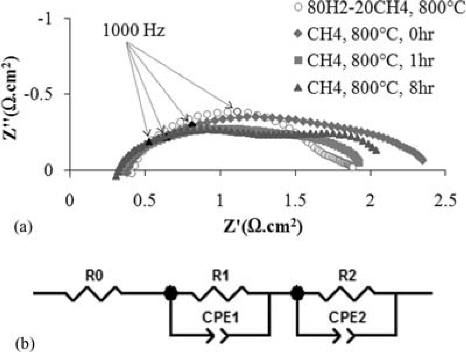
Figure 1. (a) Ac impedance spectra of a Ni-CeO2-WC-YSZ (NCWZ) symmetrical cell at 800°C under both humidified 80% H2–20% CH4 and CH4 atmospheres, (b) an equivalent circuit model.
The impedance comprises two semicircles: One arc in the high-medium frequency range (100 kHz–100 Hz) which is normally attributed to charge transfer resistance corresponding to electron transfer and ion transfer processes occurring at the interfaces,27, 28 while the other arc in the low frequency range (100 Hz–0.1 Hz) is predominantly attributed to non-charge transfer processes including surface reactions and solid state and gas phase diffusion.27, 29 As observed in Figure 1a, under the mixed fuel, the first semicircle is rather large while the second one is small. However, under methane, the arcs are about the same size. An equivalent circuit is also shown in this Figure 1b which includes the ohmic resistance corresponding to the YSZ electrolyte (R0), and the non-ohmic polarization corresponding to the composite electrode (R1 and R2). For the sake of comparison, the resistances under mixed and methane fuels are summarized in Table I. It should be mentioned that the polarization data under methane are based on the fit data for the measured impedance.
Table I. Ohmic and non-ohmic polarization of a NCWZ symmetrical cell.
| Fuel | R0 (Ω.cm2) | R1 (Ω.cm2) | R2 (Ω.cm2) |
|---|---|---|---|
| 80% H2–20% CH4 | 0.42 | 1.15 | 0.30 |
| CH4, 0 hr | 0.38 | 1.15 | 0.88 |
| CH4, 8 hr | 0.31 | 1.00 | 0.85 |
Based on numerous experiences with Ni-based anode materials in our lab, we were aware that unless the gold current collector is externally pushed against the Ni-based electrode, the attachment between them is poor. Thus, as opposed to our previous observations for WC-YSZ, CeO2-WC-YSZ and Ru-CeO2-WC-YSZ24 in which the charge transfer semicircles were dramatically smaller than the non-charge transfer ones, the fact that the high-medium frequency arc was relatively large in NCWZ under the mixed hydrogen-rich atmosphere was not surprising. The rather weak attachment between the NCWZ electrode and the gold current collector results in a higher charge transfer polarization at the electrode/current collector interface which affects the high-medium frequency arc. Interestingly, the way the impedance spectrum changes upon the introduction of methane fuel confirms this argument. As soon as the sample is exposed to methane, a large increase in the non-charge transfer polarization occurs while the charge transfer part is almost unchanged (Figure 1a and Table I). Since a gas diffusion limitation is not expected under OCV conditions,30 such an increase in the low frequency arc (R2 from 0.30 Ω·cm2 in hydrogen-rich fuel to 0.88 Ω·cm2 in methane fuel) is the inevitable corollary of surface reactions. This makes reasonable sense because methane is rather difficult to activate.31 While this arc remains rather unchanged with time under methane, a marked improvement in ohmic resistance (R0) as well as charge transfer polarization (R1) is observed. McIntosh et al.32, 33 have already reported similar performance improvement under hydrocarbon fuels and attributed it to formation of conductive carbonaceous films on the porous anode. These deposits not only increase the electrode conductivity, but they also improve the contact resistance between the electrode and current collector and, therefore, decrease the charge transfer polarization. After three hours of exposure to methane under OCV condition, the electrochemical performance became stable and no further change in polarization was observed.
Liu and Barnett7 have shown that conventional Ni-YSZ supported SOFCs are compatible with humidified methane and carbon deposition is limited during cell operation. They, however, observed that when the cell was maintained under OCV condition, a substantial buildup of carbon on the anode occurred. Their work suggests that carbon deposition on Ni-based anodes is mainly a concern under open circuit condition. Therefore, an impedance study under OCV was considered. Figure 2 shows the impedance spectra of a symmetrical NCWZ cell under OCV condition at 850°C under humidified methane. Impedance measurements were made every hour for a period of 48 hr. The result is rather astonishing: no carbon formation is observed under OCV at a temperature as high as 850°C with humidified methane. Except the initial impedance which was slightly larger, the others were about the same. While the charge transfer arc remained identical for all measurements, a very small fluctuation in non-charge transfer polarization was observed. The three spectra (after 6, 12 and 36 hr) illustrated in Figure 2 are only examples of measured impedances. Also, after the test, the sample was visually inspected and no coking was observed. Considering the fact that the electrode contained 5 wt% Ni, this result strongly motivated us to investigate how a fuel cell with a NCWZ anode performs under methane.
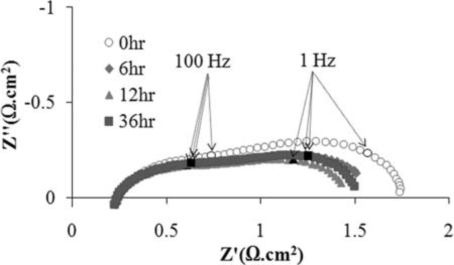
Figure 2. Ac impedance spectra of the symmetrical NCWZ cell under OCV condition at 850°C under humidified methane.
Figure 3 shows an SEM micrograph of the symmetrical cell after being exposed to methane under open circuit condition for a period of 48 hr at 850°C. The dense layer on the right is the YSZ electrolyte, the 30 μm porous layer in the middle is the Ni-CeO2-WC-YSZ electrode and the layer on the left which contains large spherical particles is the gold current collector. Several observations should be noted from this figure. First, the electrode layer is quite well attached to the electrolyte and its structural integrity is maintained. Second, the NCWZ electrode shows a very uniform microstructure and the porous YSZ support is homogeneously covered with infiltrated components (WC, Ni and ceria). Third, the electrode is sufficiently porous after incorporation of 20 vol.% WC, 5 wt% Ni as well as 5 wt% ceria. Finally, no coking is observed throughout the electrode.
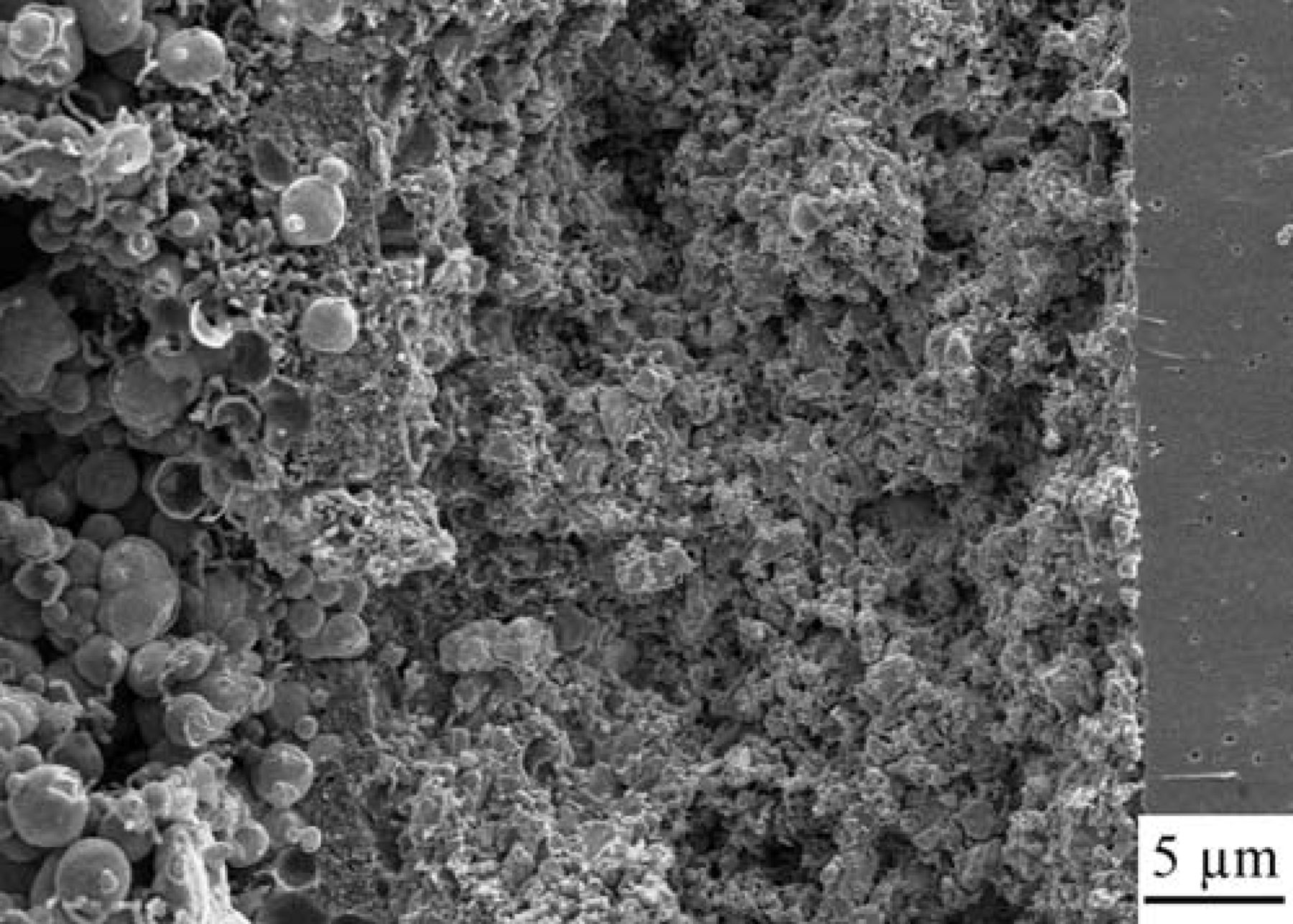
Figure 3. SEM micrograph of the symmetrical NCWZ cell after being exposed to methane under OCV for 48 hr at 850°C.
Fuel cell studies
The ac impedance spectra of a fuel cell with a Ni-CeO2-WC-YSZ anode at 850°C under humidified 80% H2–20% CH4 mixed atmosphere and humidified methane is illustrated in Figure 4. As described previously, the total polarization (the difference between the high frequency and low frequency intercepts with the real axis) of a half cell with the Ni-CeO2-WC-YSZ electrode is 1.45 Ω·cm2 at 850°C for the mixed fuel under OCV. Also, it was shown elsewhere34 that the total polarization of a half cell with an LSM infiltrated porous YSZ electrode is <0.1 Ω·cm2 under air at the same condition. Thus, we reasonably expect that under open circuit condition, the total polarization of a cell with a Ni-CeO2-WC-YSZ anode and an LSM infiltrated porous YSZ cathode to be about 1.55 Ω·cm2. The measured total polarization is 1.5 Ω·cm2 which is in a good agreement with the earlier results. Note that the cathodic contribution to the total polarization is quite small.
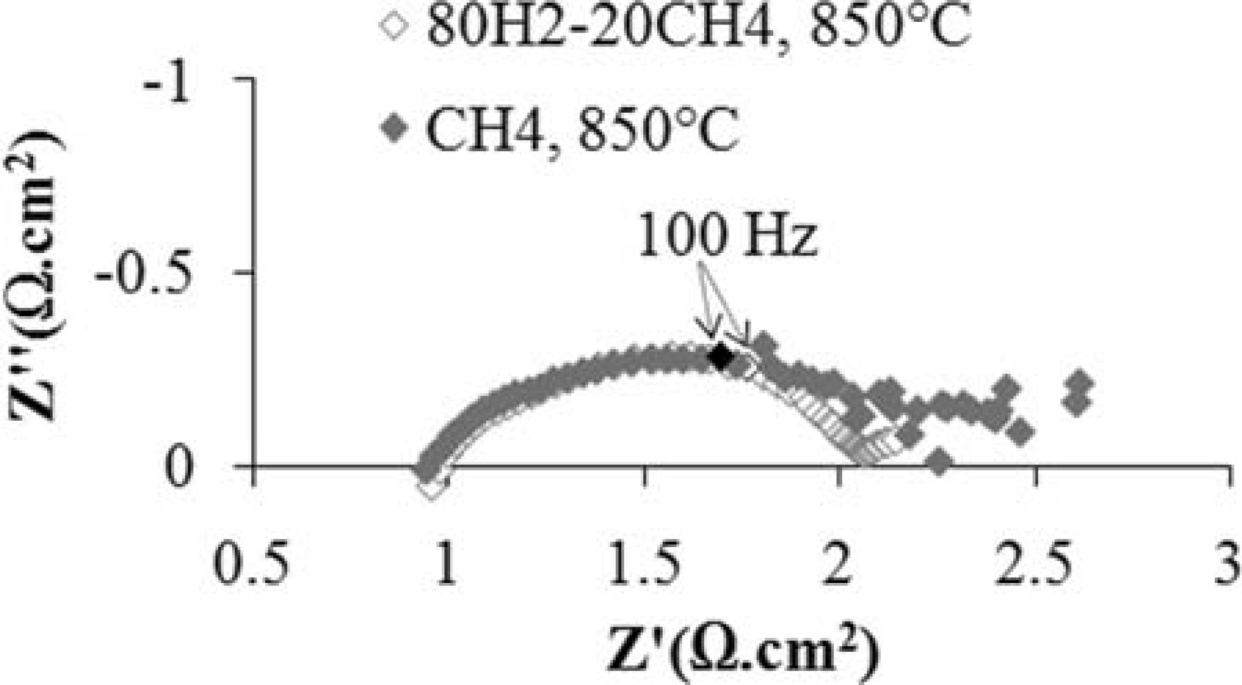
Figure 4. Ac impedance spectra of a cell with a Ni-CeO2-WC-YSZ anode at 850°C under humidified 80% H2–20% CH4 atmosphere and humidified methane.
As observed in Figure 4, with both mixed and methane fuels, the impedance comprises three semicircles: one in the high frequency range, one in the medium frequency range and the last arc in the low frequency range. Interestingly, when the hydrogen-rich fuel was replaced with methane, the first two semicircles remained unchanged while a slight increase occurred in the low frequency lobe. Thus, similar to the NCWZ half cell, what actually controls the low frequency polarization is the anodic surface reactions. In addition, from the data in Figure 4, the ohmic resistance of the cell is 0.97 Ω·cm2 under the mixed fuel and 0.94 Ω·cm2 under methane. Similar to the NCWZ half cell, such a decrease in the ohmic resistance has to do with the formation of conductive carbonaceous films on the porous anode.
The V-i characteristics and power densities at 850 and 900°C under the two fuels are shown in Figure 5. Open circuit voltages decrease with increasing temperature. For example, under methane, the OCV is 1.00 and 0.97 V at 850 and 900°C, respectively. While the cell performance is higher with the humidified 80% H2–20% CH4 atmosphere at both temperatures, the performance under humidified methane is reasonably close (only about 15% lower). This is not surprising because, as observed in Figure 4, surface reaction polarization was only slightly larger under methane fuel. Table II compares the maximum power densities of this cell with a Ni-CeO2-WC-YSZ anode and an earlier cell with a Ru-CeO2-WC-YSZ anode (RCWZ, 1 wt% Ru and 5 wt% ceria) with a similar electrolyte and cathode.24, Interestingly, performance of the cell with the Ni modified anode is markedly higher under methane (e.g. 131 mW·cm−2 versus 83 mW·cm−2 at 900°C).
Table II. Power densities of cells with Ni-CeO2-WC-YSZ (NCWZ) and Ru-CeO2-WC-YSZ (RCWZ)24 anodes.
| P (mW.cm−2), NCWZ | P (mW.cm−2), RCWZ | |||
|---|---|---|---|---|
| Temperature (°C) | 80–20 mix | CH4 | 80–20 mix | CH4 |
| 850 | 103 | 86 | 185 | 58 |
| 900 | 153 | 131 | 263 | 83 |
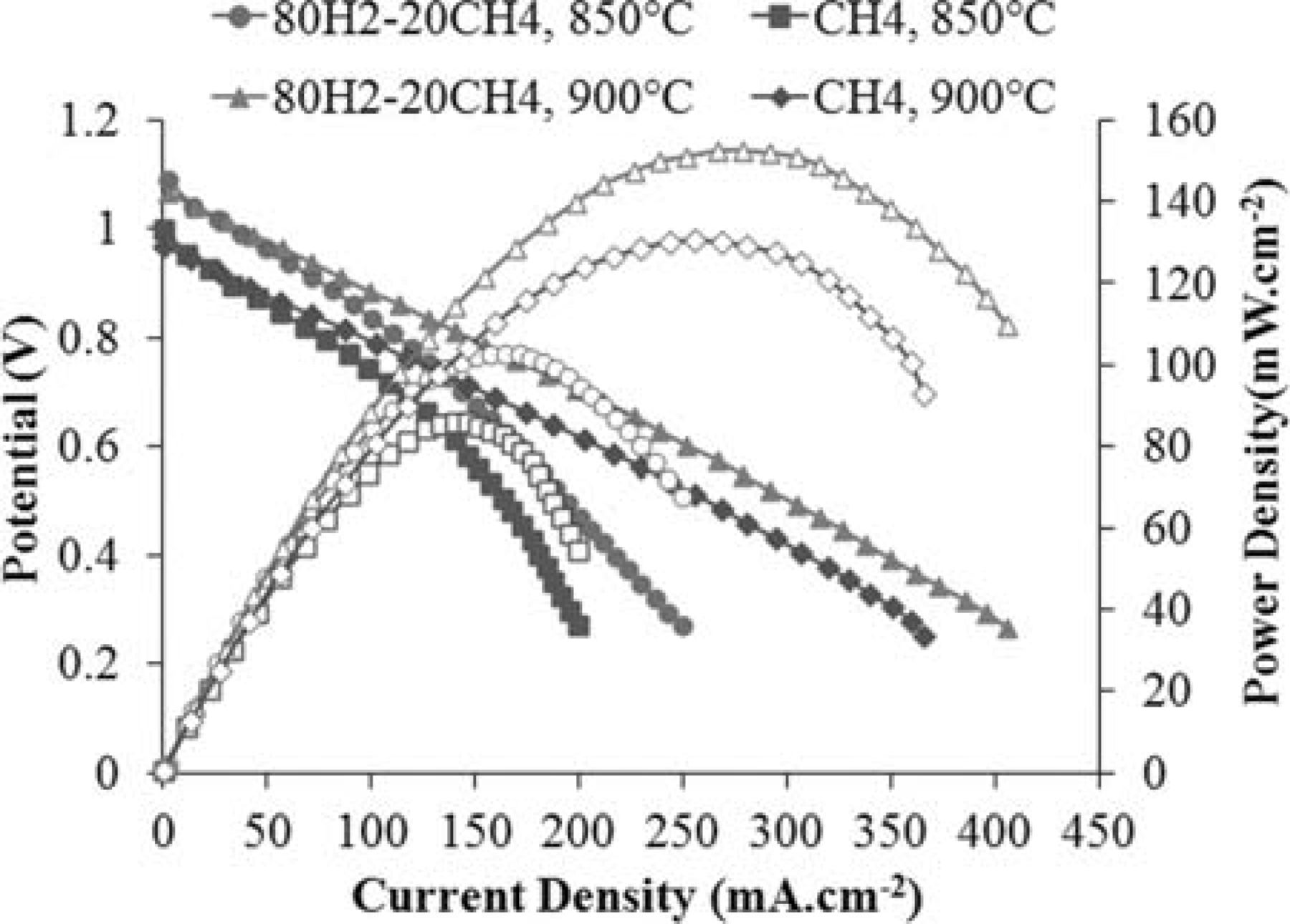
Figure 5. V-i characteristics and power densities of the cell with a Ni-CeO2-WC-YSZ anode at 850 and 900°C under the two fuels.
An SEM micrograph of a Ni-CeO2-WC-YSZ anode is illustrated in Figure 6. The lower magnification image shows that the porous YSZ support is uniformly covered with a connected network of the carbide phase. EDS analysis was done over numerous points throughout the anode in order to differentiate among the infiltrated phases. This was, however, quite challenging because of resolution limitations of the chemical analysis at high magnifications. Since Ni and ceria were incorporated after the carbide phase was formed, the nano-size particles dispersed throughout the WC-YSZ network are Ni or ceria. Note that ceria particles are the smallest features in the range of 10–20 nm and Ni particles are those brighter ones in the range of 50–100 nm.
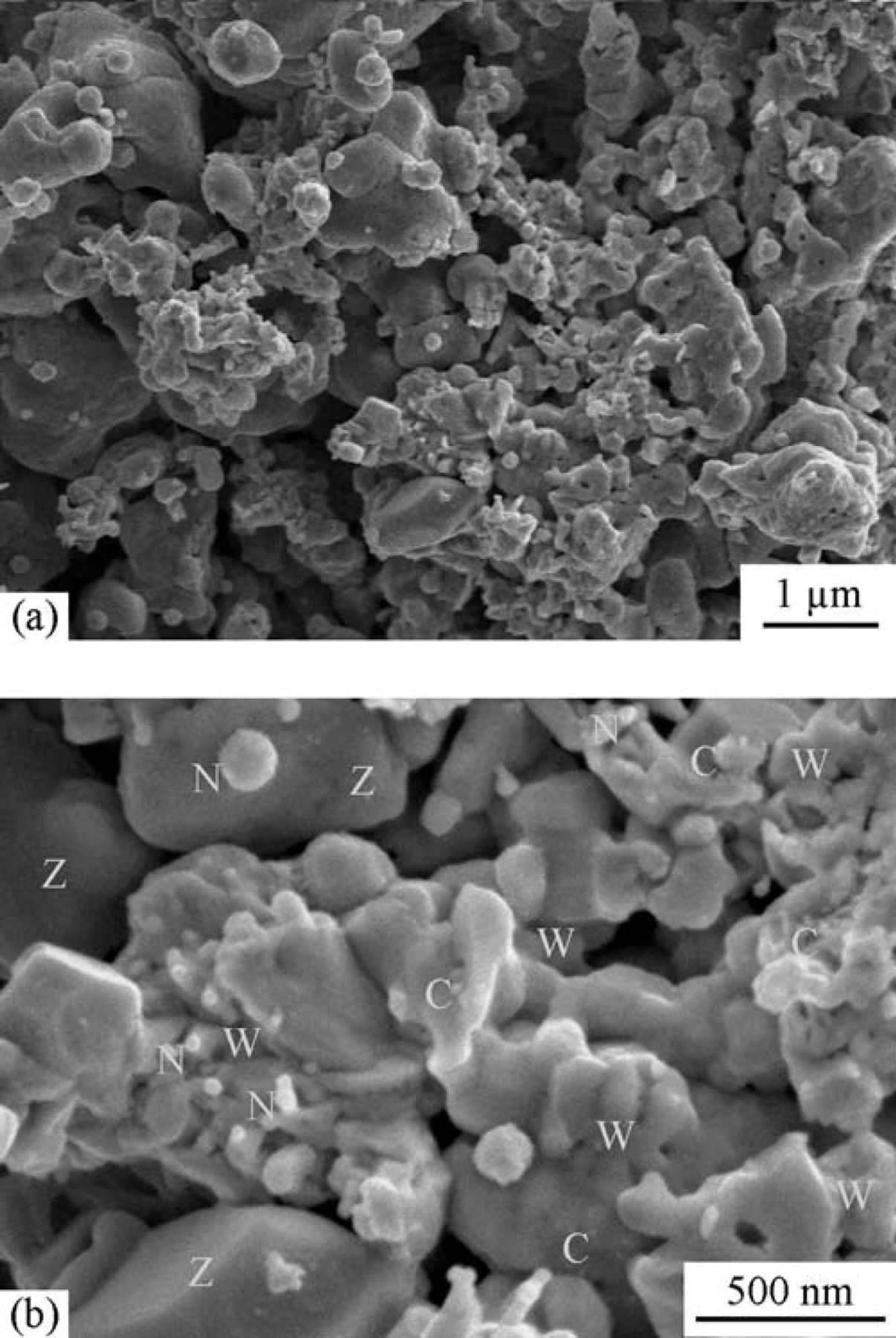
Figure 6. SEM micrographs of the Ni-CeO2-WC-YSZ anode.
Stability issue
Figure 7 shows how stable the cell with a Ni modified anode is under humidified methane. The stability test was done under a constant voltage of 0.7 V at 850°C for a period of 24 hr. A marked decrease in power density (about 35%) was observed in the first 15 min of the experiment. As discussed elsewhere,24 surface oxidation of the carbide phase is one of the two possible mechanisms of the fuel oxidation process. Before polarization, the fresh surface layer of WC nano-particles is very active toward the fuel which is why the performance is relatively high at the very beginning. Several minutes after polarization, however, the carbide surface gradually approaches an equilibrium oxidation state and the performance stabilizes. It is quite remarkable that no degradation was observed during the course of this experiment, neither because of instability of the carbide phase nor due to carbon formation on the Ni modified WC-based anode. When WC-based materials are considered as alternative anodes, the stability of the carbide phase is one of the major concerns. As reported elsewhere,24 in a polarized cell with a WC-YSZ anode under methane fuel, a major phase change from WC to W occurs which is unavoidably governed by kinetic reasons. However, we showed that when the WC-YSZ anode is modified by Ru-ceria, the carbide phase is preserved to a great extent. Figure 8 shows the XRD spectrum of a NCWZ anode tested for more than a week. As observed, the carbide phase remains stable, no tungsten metal is detected and only a very minor tungsten oxide phase appears. Our previous work on WC-based anodes24 suggests that surface oxidation of the carbide phase is actually one of the possible mechanisms of the fuel oxidation process and as long as the rate of carbide oxidation and that of oxide recarburization remain about the same, the cell performance is stable. The rather stable performance of the Ni modified carbide based anode, thus, supports the previous argument. Figure 9 shows the OCV impedance spectra of the cell before and after the stability test at 850°C under methane. Intriguingly, the cell polarization remained rather unchanged. This further confirms the stable performance of the anode with no carbon deposition under methane.
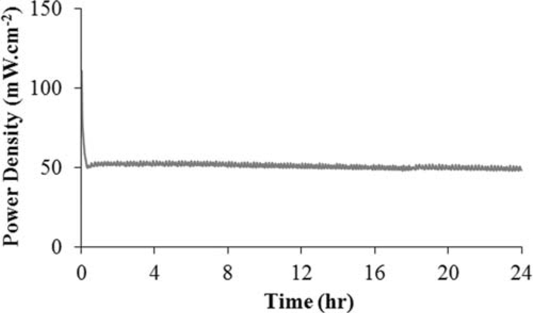
Figure 7. Performance of the cell toward humidified methane, under a constant voltage of 0.7 V at 850°C for 24 hr.
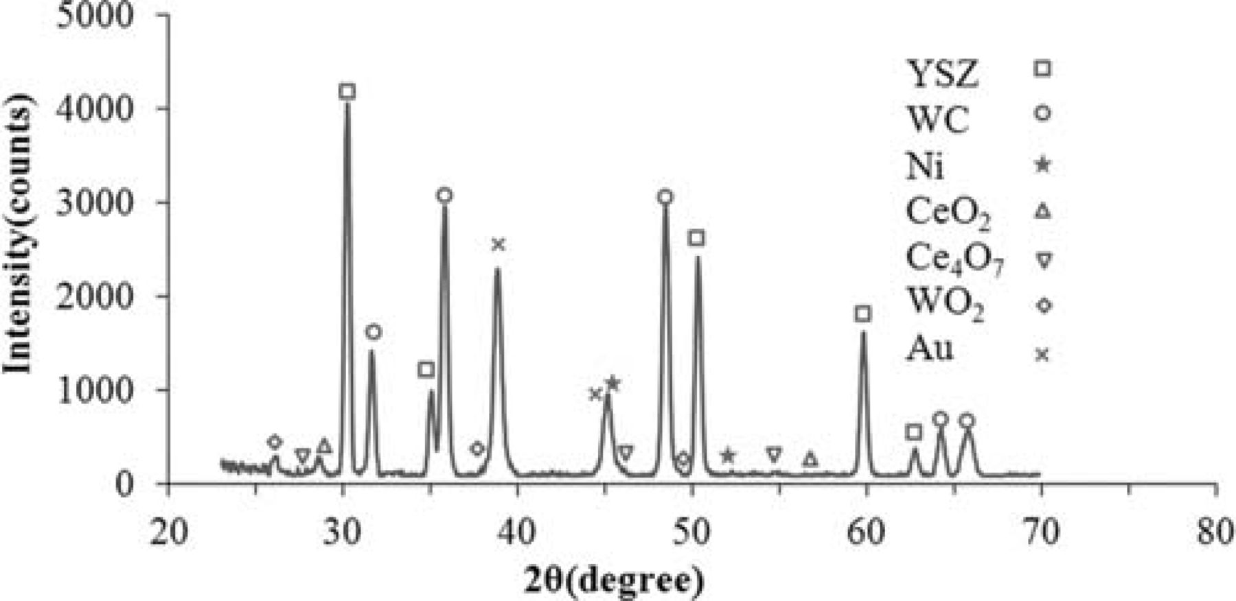
Figure 8. XRD spectrum of a NCWZ anode tested for more than a week.
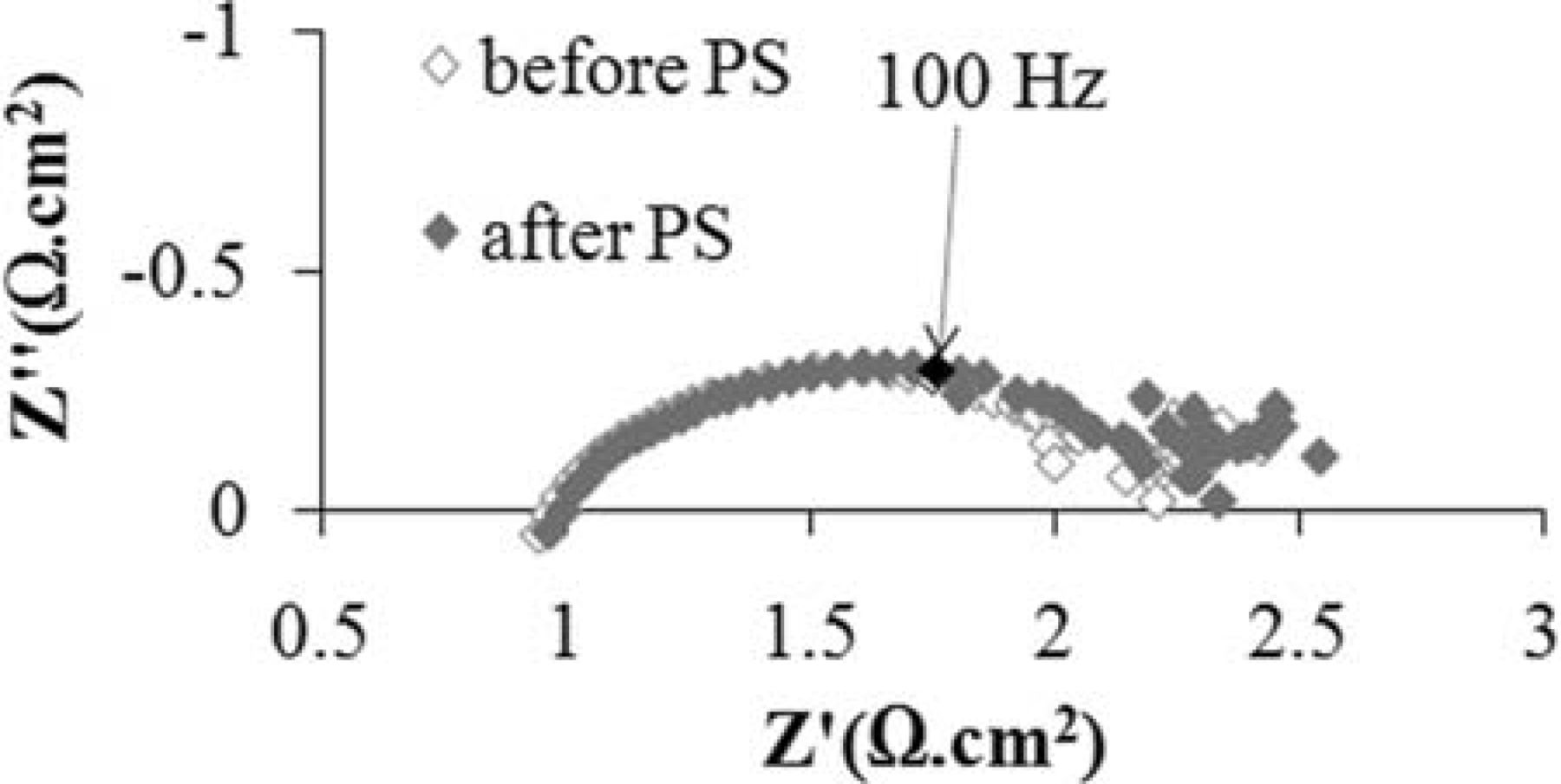
Figure 9. OCV impedance spectra of the cell before and after the stability test at 850°C under methane.
In our previous work24, 25 we have proposed a series of electrochemical reactions which possibly occur over a carbide-based anode. Briefly, these reactions include:
![Equation ([1])](https://content.cld.iop.org/journals/1945-7111/159/6/B714/revision1/jes_159_6_B714eqn1.jpg)
![Equation ([2])](https://content.cld.iop.org/journals/1945-7111/159/6/B714/revision1/jes_159_6_B714eqn2.jpg)
![Equation ([3])](https://content.cld.iop.org/journals/1945-7111/159/6/B714/revision1/jes_159_6_B714eqn3.jpg)
![Equation ([4])](https://content.cld.iop.org/journals/1945-7111/159/6/B714/revision1/jes_159_6_B714eqn4.jpg)
![Equation ([5])](https://content.cld.iop.org/journals/1945-7111/159/6/B714/revision1/jes_159_6_B714eqn5.jpg)
![Equation ([6])](https://content.cld.iop.org/journals/1945-7111/159/6/B714/revision1/jes_159_6_B714eqn6.jpg)
![Equation ([7])](https://content.cld.iop.org/journals/1945-7111/159/6/B714/revision1/jes_159_6_B714eqn7.jpg)
![Equation ([8])](https://content.cld.iop.org/journals/1945-7111/159/6/B714/revision1/jes_159_6_B714eqn8.jpg)
As Claridge et al.35 pointed out, methane conversion over a carbide catalyst can be explained by two different pathways: a redox mechanism (equation 5) in which an adsorbed oxygen atom (O*, equation 1) reacts with a carbon atom from the carbide surface and a noble metal mechanism (equation 6) in which the oxygen atom reacts with an adsorbed carbon atom (C*, equation 2). The former results in carbon vacancies in the carbide phase which are to be filled with either carbon or oxygen (equations 7 and 8). Carbon atoms from WC, however, do not play a role in the noble metal mechanism and remain intact. In practice, both of these mechanisms decisively participate in the overall reaction.35
The stability challenge in WC-based anodes particularly under methane fuel has already been discussed.24 Also, the problem with carbon formation in Ni-based anodes is well appreciated.1 Surprisingly, an anode based on WC and Ni not only performs stably with no undesirable phase transformation, but also does not promote the build up of carbon at temperatures as high as 850°C. Nickel is a well known catalyst for the formation of carbon fibers.4 Carbon deposition on a Ni surface is the fundamental step in carbon fiber formation. The deposited carbon is then dissolved from the surface into the bulk of the Ni catalyst and finally precipitates as carbon fibers. Gross et al.4 further argued that what makes the Ni-based anodes incompatible with hydrocarbon fuels is in fact not carbon deposition itself, but the bulk dissolution followed by fiber precipitation. Furthermore, as discussed by Mogensen and Kammer,36 direct electrochemical oxidation of methane is normally unfavorable in nickel-based anodes; instead, methane predominantly cracks over the Ni catalyst and the cracking products contribute toward electrochemical performance.
As for the Ni modified WC-based anode, a plausible scenario could be as follows: On the one hand, carbon deposition occurs on Ni surface as expected with methane fuel at temperatures as high as 850°. On the WC surface, on the other hand, carbon vacancies are formed as the inevitable result of the redox mechanism. Since nickel is supported by the tungsten carbide network (Figure 6), it donates the surface carbon to the carbide with carbon shortage (equation 7). This is a win-win exchange: the Ni surface becomes carbon-free and can continue to play a role as an electrocatalyst while WC remains stable and can contribute to methane oxidation. The solid state reaction between transition metals such as W and Mo and an in-situ source of carbon to form carbides is not new.37, 38 For example, Zhu and Manthiram37 showed that a polymer precursor can be used as an in-situ source of carbon instead of gas phase carburization to synthesize tungsten carbide. These works reasonably support our above mentioned scenario.
In order to ensure that WC plays a critical role in the removal of deposited carbon, behavior of an anode based solely on Ni-WC-YSZ under humidified 80% H2–20% CH4 and humidified methane fuels at 850°C was also studied. As expected, a rather large performance decrease was observed. For example, the total cell polarization under open circuit condition was 5.8 Ω·cm2 for a cell with a Ni-WC-YSZ anode as opposed to 1.3 Ω·cm2 for a cell with a Ni-CeO2-WC-YSZ anode, under the humidified 80% H2–20% CH4 fuel. However, quite similar to the Ni-CeO2-WC-YSZ, the anode without ceria showed a steady performance and no carbon formation was observed. Figure 10 presents an SEM micrograph of the Ni-WC-YSZ anode operated on humidified 80% H2–20% CH4 and humidified methane fuels for 72 hr. As the image indicates, no carbon fiber is observed and the Ni particles (dispersed spherical spots which look slightly brighter) are well attached to the WC-YSZ support. In addition, phase analysis (XRD) of this anode confirmed that the WC remained chemically stable.
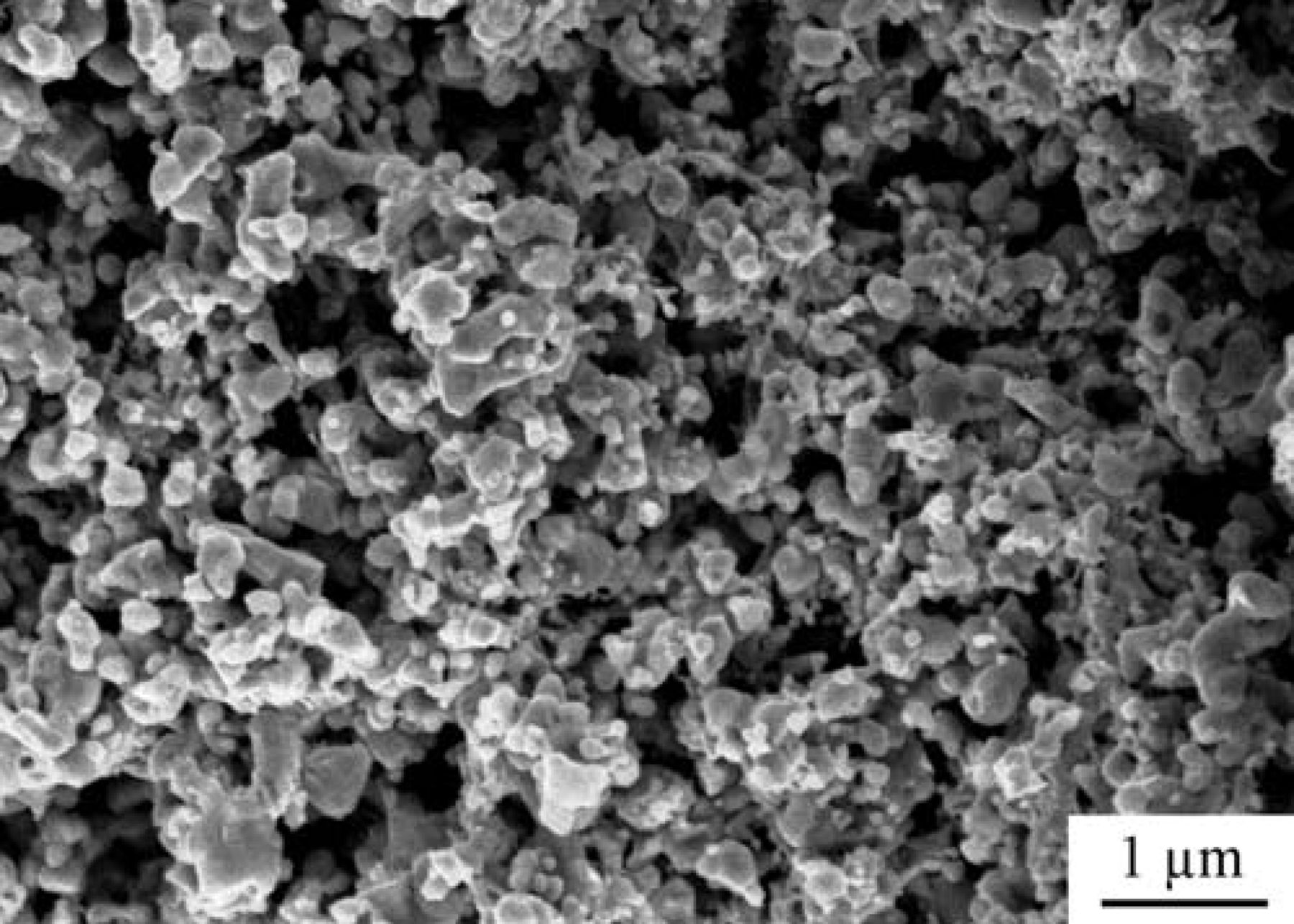
Figure 10. An SEM micrograph of the Ni-WC-YSZ anode operated on humidified 80% H2–20% CH4 and humidified methane fuels.
Note that the possible role of ceria in suppression of carbon formation is not being overlooked. Ceria is known to be an oxygen donor in reducing atmospheres and it essentially contributes to electrochemical oxidation of the carbon.36 Nonetheless, it was shown25 that an anode based on CeO2-WC-YSZ suffers from chemical instability. More importantly, the facts that WC is preserved and no carbon fiber formed in anodes with and without ceria indicate that the carbide phase actively participates in removal of the deposited carbon. It should be emphasized that since the idea of an alternative anode based on WC and Ni is novel, more investigation is required to fully understand the mechanism which results in such a dual role: to suppress carbon deposition and to stabilize the carbide phase.
Redox issue
One of the more significant challenges of Ni-based anodes (the state-of-the-art anode materials for SOFCs) is their poor mechanical stability during reduction/oxidation cycles. While the anode normally performs under reducing conditions, it may experience several reduction/oxidation (redox) cycles during its lifetime because of accidental occurrences such as failure in the fuel supply, a broken seal and substantial fuel utilization.39 When a cell goes through a redox cycle, the Ni-based anode experiences a significant volume change which causes a great deal of mechanical stress on this electrode. This is a serious threat to the cell integrity particularly when the cell is mechanically supported by the anode and may result in catastrophic failure of the cell.
Similar to cells based on a Ni-YSZ anode, redox cycling could be a serious concern in SOFCs with WC-based anode materials. Upon oxidation, tungsten carbide experiences a large volume change (theoretical density of WC and WO3 are 15.8 and 7.2 g·cm−3, respectively) which imposes a significant mechanical stress on the anode. In a conventional composite WC-YSZ anode in which the carbide is actually a structural component of the electrode, this internal stress could devastate the structural integrity. Thus, in order for the WC-based anode to be a viable alternative, this issue needs to be addressed.
Recently, highly redox resistance tubular SOFCs with a Ni-YSZ anode were successfully developed.40 In the current work, we used the same approach to address the redox issue. Figure 11 schematically shows the concept which lays behind this design. First, a robust YSZ-based cell which includes a thick (hundreds of microns) porous YSZ support, a thin (tens of microns) gastight YSZ electrolyte and a thin (tens of microns) porous YSZ is fabricated (Figure 11a). The anode and cathode of choice are then incorporated into the thick and thin porous YSZ layers, respectively, by a post infiltration process (Figure 11b). The major advantage of this design over the conventional one is that the infiltrated material does not contribute to the structural integrity of the cell. Additionally, while a conventional cell typically needs 50 wt% of the electronically conductive component to reach the percolation threshold, the required amount is significantly less in infiltrated cells,24 which also contributes to redox resistance.
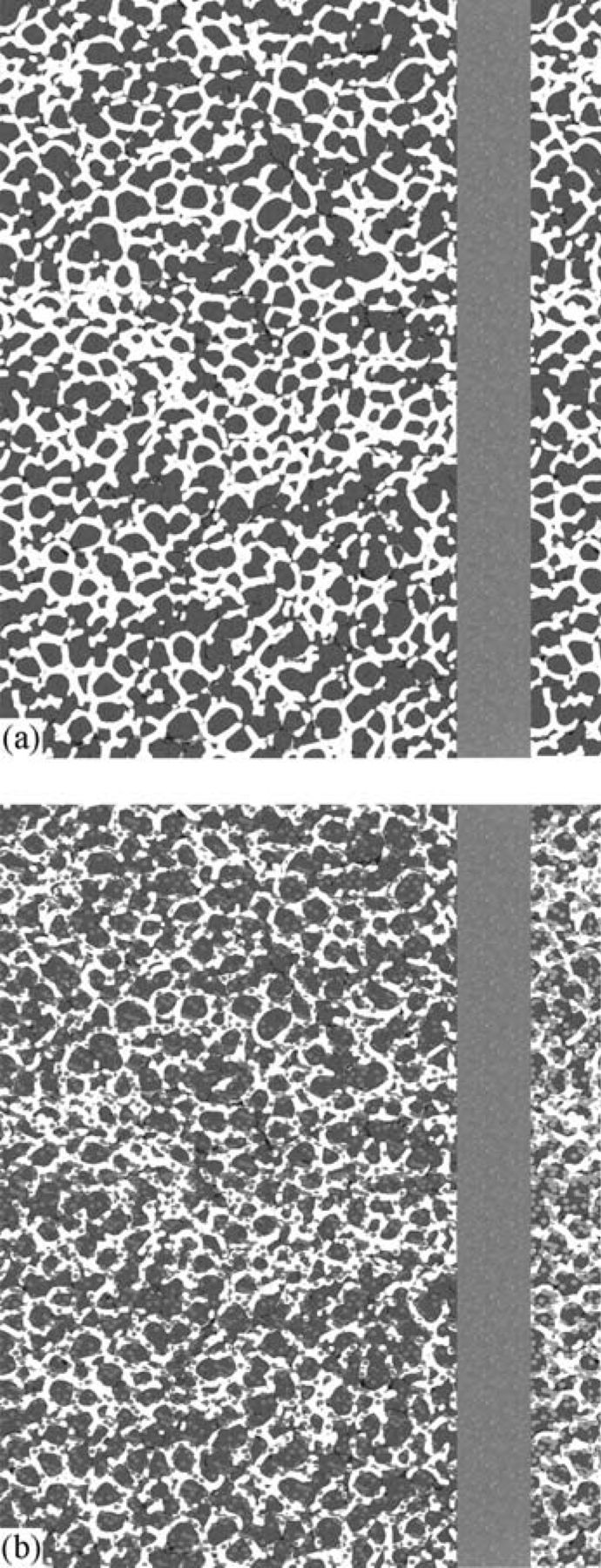
Figure 11. Schematic drawing of the cell configuration, (a) before and (b) after infiltration.
Figure 12 illustrates how the open circuit potential changes during an oxidation-reduction cycle at 850°C. At the very begining, the cell is under humidified methane and the OCP remains at 0.98 V (part I). Methane is then flushed out by a neutral gas, Ar, for a period of 15 min when the OCP drops to 0.84 V (part II). When air is introduced, the OCP drops to zero within a minute (part III). Once the anode is oxidized, the air is removed by Ar and the OCP quickly jumps back to 0.82 V (part IV). Finally, humidified hydrogen is introduced and only a few minutes are enough for the OCP to remain stable at 1.08 V.
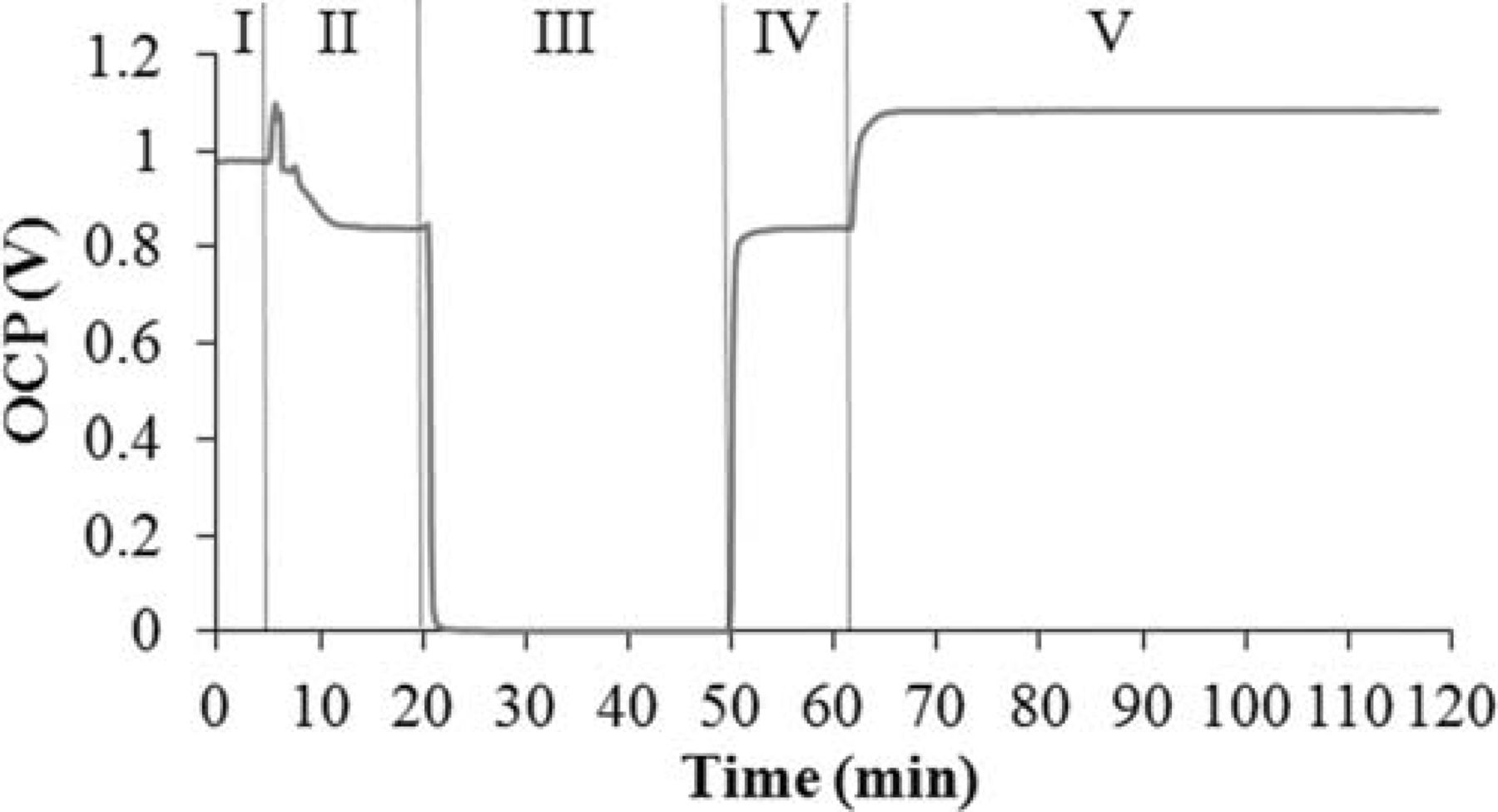
Figure 12. OCV change of the cell during an oxidation-reduction cycle.
After a cell goes through an oxidation-reduction cycle, the anode contains no carbide phase. Thus, the anode was treated under the 80% H2–20% CH4 atmosphere at 850°C for a period of 18 hours. Figure 13 shows how the impedance of the cell behaves during the course of recarburization. This figure contains very informative data and several observations should be pointed out. First, and perhaps the most important is that the structural integrity of the cell is maintained and no delamination occurs. Secondly, at 850°C under 80% H2–20% CH4 atmosphere, it takes three hours for the anode to revive. The impedance spectrum after the first hour shows that the ohmic resistance of the cell is more than twice that of the original cell with a WC-based anode (2.15 Ω·cm2 vs. 0.97 Ω·cm2). The total polarization of the cell at this stage is also relatively high (7.35 Ω·cm2 as opposed to 1.5 Ω·cm2). After three hours, however, the ohmic resistance and total polarization of the cell are 0.99 and 1.7 Ω·cm2, respectively, which are reasonably close to those before the redox cycle. Finally, while the cell shows a lower ohmic resitivity after recarburization (the total ohmic resistance of the cell is 0.9 Ω·cm2), the total polarization is slightly higher. This slight change is essentially the inevitable corollary of microstructural alteration due to the oxidation-reduction-recarburization process.
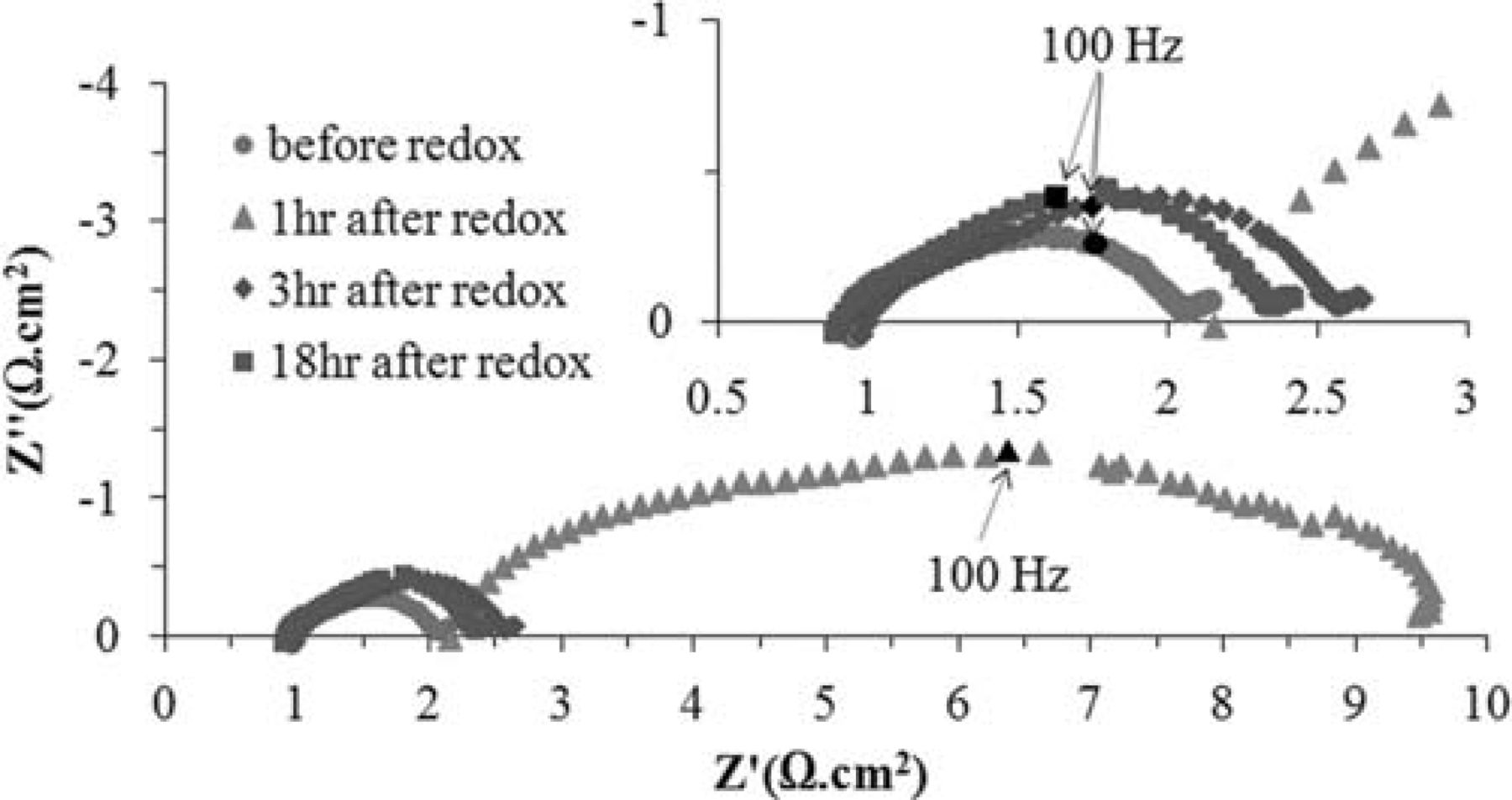
Figure 13. OCV impedance behavior of the cell during recarburization after the oxidation-reduction cycle.
The V-i characterization of the cell during the recarburization process is demonstrated in Figure 14. As observed, the result is rather consistent with how the impedance evolves. At the beginning, when the ohmic resistance is rather high and the total polarization is relatively large, the cell performs rather poorly and the maximum power density is only 40.7 mW·cm−2 (originally 102.8 mW·cm−2). However, after three hours, when the ohmic resistance of the cell becomes close to that of the original cell, it performs similarly. Interestingly, a remarkable improvement in cell performance occurs upon continuation of the recarburization process. After 18 hr of recarburization, the final power density is 152.8 mW·cm−2, which is a 48.6% increase compared to that of the original cell.
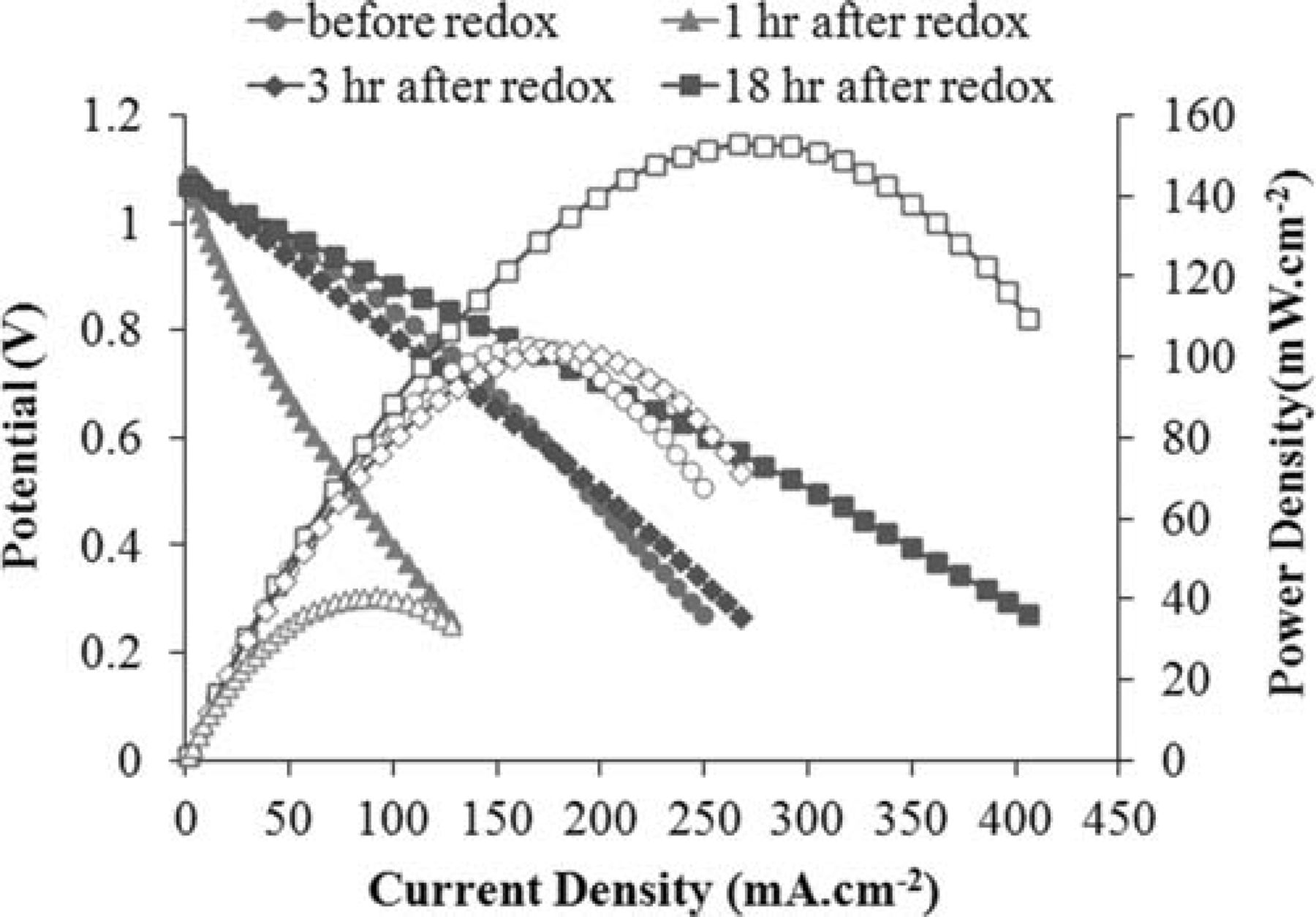
Figure 14. V-i behavior of the cell during the recarburization process.
After recarburization, stability of the cell performance was also studied at 850°C with humidified 80% H2–20% CH4 and methane fuels. The cell was polarized at 0.7 V for a period of 24 hr under each fuel. Similar to the original cell, very stable behavior was observed in both cases. Figure 15 shows the OCP impedance spectra of the recarburized cell before and after a 24 hour potentiostatic test at 850°C under the mixed fuel. Since the cell was kept polarized at 0.7 V for the duration of the test, an impedance spectrum of the polarized cell is also included in this figure. While the ohmic resistance of the cell remains unchanged, a minor decrease in the total polarization is observed. Note that only the low frequency region of the impedance plot is slightly changed. The stable behavior of the polarized cell after the oxidation-reduction-recarburization cycle also suggests that the structural integrity of the cell remained intact. It is noteworthy that the post-analysis XRD test on this anode confirmed that the carbide phase was completely revived and neither tungsten metal nor oxide was observed (the XRD pattern was very similar to Figure 8 and, therefore, is not show here).
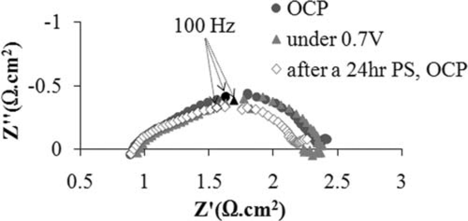
Figure 15. OCV impedance spectra of the recarburized cell before and after a 24 hour potentiostatic test at 850°C under the mixed fuel.
An SEM micrograph of the interface between the Ni-CeO2-WC-YSZ anode and YSZ electrolyte after an oxidation-reduction-recarburization cycle is shown Figure 16. As suggested by the electrochemical analysis, the image also confirms that the structural integrity of the cell was maintained and no delamination and/or micro-cracks are observed along the interface. Furthermore, the porous YSZ support is uniformly and intimately covered with the infiltrated components (WC, Ni and ceria). Lastly, no carbon fiber formation is observed throughout the electrode.
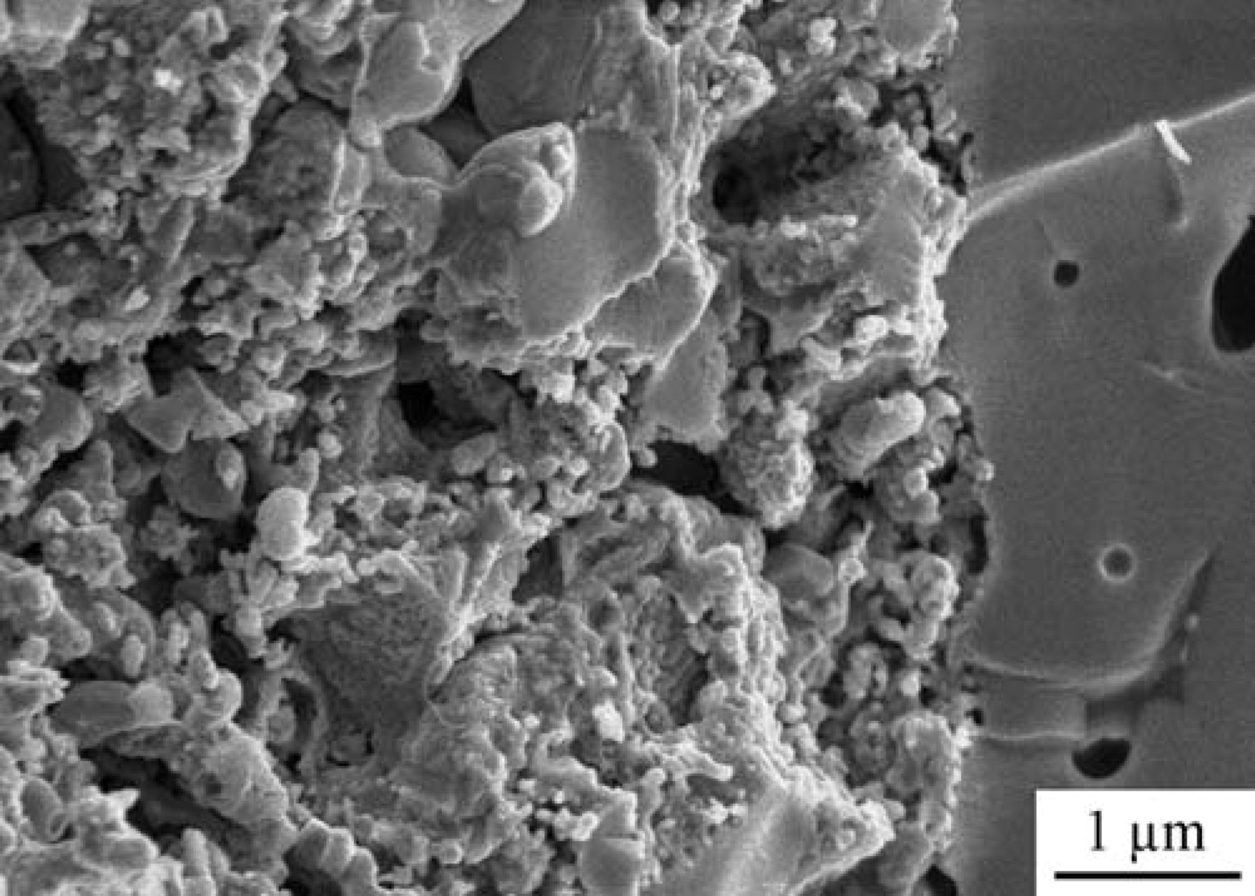
Figure 16. SEM micrograph of an interface between the Ni-CeO2-WC-YSZ anode and YSZ electrolyte after the oxidation-reduction-recarburization cycle.
WC as an anode material
Our interest in investigating WC as a potential candidate was based on several intriguing attributes of this material including catalytic resemblance between WC and precious metals, tolerance against carbon formation, very high electronic conductivity (0.52 × 10⁵ S·cm−1 for WC vs. 1.43 × 10⁵ S·cm−1 for Ni25) and very high melting point (2870°C) as a reasonable guarantee of microstructural stability. Nevertheless, previous work24 revealed that there are two major challenges in regard to WC-based anodes: their activity toward methane fuel is relatively poor and needs to be improved, and they may experience chemical instability under cell operating conditions.
Therefore, the idea of using Ni to modify the WC-based anode was not only to improve but also to stabilize the performance. As discussed above, the redox mechanism is one of the active pathways of methane oxidation on a WC surface which involves surface carbon atoms from the carbide phase (equation 5). As long as the rate of carbide oxidation and that of metal and/or oxide recarburization remain about the same, the cell performance will be stable. In a conventional WC-YSZ electrode with methane fuel, under cell operation conditions the recarburization reaction is kinetically less favorable and the carbide phase is unstable. Under such circumstances, carbon formation is in fact advantageous: an in-situ source of carbon is supplied to preserve the carbide from being depleted of carbon. Thus, when a WC-based anode is modified with Ni, not only can the attributes of nickel can be taken advantage of, but its tendency toward catalyzing the buildup of carbon could be beneficial. This is actually a win-win situation: on the one hand stability of the carbide phase and on the other hand no destructive carbon formation.
The cell design and fabrication process proposed here can reasonably address other challenges posed by the high processing temperature and low coefficient of thermal expansion (CTE) of WC as well as its significant volume change during redox cycling. Firstly, the carbide can be incorporated into the porous YSZ support with a very simple and practical infiltration technique followed by a low temperature heat-treatment. In addition, since a nano-sized carbide network is formed within the YSZ support, the amount of carbide to meet the electronic conductivity requirement is significantly less than what it is in a conventional WC-YSZ composite. The less WC incorporated into the anode, the less problematic is the CTE mismatch and redox cycling. Finally, since WC does not play any structural role whatsoever, the structural integrity of the cell can be maintained during redox cycling and a catastrophic failure can be avoided.
At last, as far as the cell performance goes, there is definitely room for improvement: the electrode support configuration should be considered, the microstructure of incorporated WC needs to be improved, and the amount of the infiltrated components must be optimized.
Conclusions
This study shows that modifying a WC-based anode by Ni electrocatalyst can successfully address the stability challenge posed by tungsten carbide and the carbon formation challenge posed by Ni. Exposed to humidified (3% H2O) methane for a course of 48 hr at 850°C, the Ni modified WC-based anode performs stably under open circuit condition and no carbon formation is observed. The cell also maintains its steady performance under polarized condition during which the carbide phase remains stable and does not experience any catastrophic phase change. Lastly, the proposed configuration highly reinforces the cell so that it successfully withstands oxidation-reduction-recarburization cycles and structural integrity is maintained.
Acknowledgments
This work was financially supported by the Natural Sciences and Engineering Research Council of Canada (NSERC).