Abstract
In here, we have reviewed the major FET sensor methodologies developed for biosensing applications. Each of the methodologies offer different approaches to mitigate the effects of charge screening in high ionic strength solutions. We focus in detail on the study of high field gated FET biosensors developed to directly detect target analytes in physiological salt environments, without extensive sample pre-treatments. Several biomedical applications are illustrated in this review cum original research article, such as protein detection in buffer/serum/whole blood, nucleotide detection in buffer, whole cell-based sensor and characterization of biological tissues. The mechanism of detection beyond Debye length in high ionic strength solutions is investigated. The integrated portable biosensor system developed based on the high field gated FET biosensor demonstrates potential for clinical applications in point of care and home-care diagnostics.
Export citation and abstract BibTeX RIS

This is an open access article distributed under the terms of the Creative Commons Attribution 4.0 License (CC BY, http://creativecommons.org/licenses/by/4.0/), which permits unrestricted reuse of the work in any medium, provided the original work is properly cited.
Field effect transistor (FET) based sensors ever since inception has piqued scientific interest due to extremely high sensitivity, ease of signal read out and label free assay capability. Various applications have been demonstrated in the past few decades including pH sensing, ion sensing, gas sensing and biomolecule sensing.1–5 Different FET sensor designs were realized using silicon nanowire FETs, graphene FETs and compound semiconductor FETs, to name a few.5–11 In biomedical applications, FET sensors are highly significant because they possess the ability to directly translate the biological interactions at the device surface, to readable electrical signals which can be processed with ease. The challenges in the field of FET based biosensing primarily revolves around the problem of charge screening effect seen at the solid/liquid interface.12 In this part review, part original research article, we evaluate and study the various methodologies adopted in the arena of FET based biomolecule sensing and demonstrate the design, fabrication and characteristics of high field modulated FET biosensor. We have demonstrated the applications of the unique FET biosensor that transcends from simple to complex assembly of macromolecules: proteins, nucleotides, cells and tissues. A comprehensive view of the sensing methodology is also envisioned in this work to elucidate the promising future of this technology in biomedical engineering.
FET based biosensors are surface affinity type sensors that rely on the molecular recognition property of surface immobilized receptor and biological target in the test solution.2,3 The specific interaction of receptor-ligand is translated into electrical signal by the FET. In traditional FET biosensor design, the gate region of FET is functionalized with the receptor, either directly on the semiconductor channel region,13 or the gate metal.14 The changes in potential resulting from the receptor-ligand binding directly modulates the transistor drain current, which is similar to applying gate voltage to control the channel conductivity. The changes in the drain current are correlated with the concentration of the target analyte present in the test solution. This traditional design of FET biosensor also involves a third electrode called the reference electrode which is immersed in the solution and typically applied with ground potential or a low voltage to set the potential of the bulk solution.15–18 Since the potential at the reference electrode remains constant for any analyte concentration, the change in channel conductivity is directly related to the vertical electrical field modulation created at the gate region of the FET by the receptor-ligand binding. FET biosensors are thus, highly sensitive to the potential changes at the solid/liquid interface and offers a rapid, label free method to detect biological analytes. However, charge screening or Debye screening at the semiconductor device/aqueous solution interface has been a major challenge in the practical realization of FET biosensors. From the Guoy-Chapman electrical double layer model we can see the relationship of Debye length and ionic strength of the aqueous medium, shown here as Equation 1.
![Equation ([1])](https://content.cld.iop.org/journals/2162-8777/7/7/Q3032/revision1/d0001.gif)
In high ionic strength solutions such as whole blood or 1X PBS, Debye length is predicted to be ∼0.7 nm.19 Typically, the size of the receptor (such as antibody) in its native form, which is immobilized at the gate region of FET is around 10 nm, with the ligand binding site oriented upwards in the z direction. Therefore, in high salt environment, the potential changes induced by receptor-ligand binding gets screened off and are unable to modulate the channel drain current. This phenomenon at the device/solution interface poses a major challenge for clinical applications of FET based biosensors. Several strategies have been adopted to circumvent the effects charge screening. Figure 1 depicts a graphical abstract of the various designs of FET biosensors that utilize different methods to reduce/overcome the potential screening. Figure 1a shows the most commonly used strategy which entails diluting the test solution such that the Debye screening length increases 2–3 orders of magnitude.20–22 When the salt concentration of the test solution is reduced, such as from 1X PBS to 0.01X PBS, the Debye length is increased from 0.7 nm to 70 nm,19 which facilitates the transduction of the receptor-ligand binding, at the gate region of FET. Silicon nanostructure-based FET biosensors have widely employed this method to detect various biological targets such as proteins, DNA and cells.20–24 An automated microfluidic purification chip was developed to capture the target proteins directly from whole blood, wash and release them in to a 1000 times diluted buffer for detection with Si nanowire FET.20 By integrating all the pre-treatment processes in the automated chip, disease biomarkers can be easily detected from whole blood, without manual sample handling. In another study, human serum was desalted, and target protein biomarker was released in to diluted (10000 times) buffer.21 Automated sample pre-processing can avoid the handling errors and variations arising from manual operations. Such designs can enable FET sensors to be used in point of care diagnostics. However, when the ionic strength is reduced to decrease the charge screening effect, activity and binding kinetics of the target biomolecules are altered.25 Since the biomolecules closely interact with the solvent molecules to preserve their structure, a diluted test environment affects their structural and hence functional properties. This also leads to large variations in test results as assay kinetics are altered. A second approach toward mitigating the charge screening problem is depicted in Figure 1b. Receptor size can be reduced to enclose it within the Debye screening length, so that target binding can be performed in native electrolyte conditions and the induced potential changes can modulate the transistor drain current, unhindered.26–28 If protein-based receptors such as antibodies are used, they can be degraded into fragments which can fit within the Debye length. Two types of degradation strategies may be used: chemical fragmentation or enzymatic cleavage. In chemical fragmentation, typically, a mild reducing agent may be used to selectively cleave the disulfide bridges in the hinge region of the antibody.29 Since the binding sites of the antibody remain intact during the fragmentation process, the reduced IgG molecules immobilized at the device surface, will have a decreased length in the z direction. Similarly, enzymatic degradation methods use enzymes such as pepsin or papain to cleave the IgG molecules at different sites.30,31 A whole antibody molecule may be fragmented into F(ab)'2, Fab', Fab molecules which when immobilized on the device surface can remain within the Debye screening length. The receptor fragmentation methodology thus overcomes the challenges faced in diluting the test solution. Since receptor-ligand binding occurs in native electrolyte concentrations, bio-sample integrity is maintained during the assay. In another approach, electrical double layer (EDL) is targeted, as depicted in Figure 1c. Alternating current (AC) is applied to eliminate the EDL as periodically changing current polarity keeps the ions in the solution in motion, thereby hindering the formation of EDL on the solid/liquid interfaces.32–34 When EDL is eliminated in this method, it effectively extends the Debye length, which in turn facilitates the detection of target biomolecule in the test solution. The frequency of the applied AC field must be optimized to provide maximum Debye length extension in aqueous solutions. This however may also introduce bulk resistance into the system's transfer function, as ions in motion generate additional impedance. Another efficient and simple strategy is to utilize the EDL to detect biomolecules beyond the Debye length. This is depicted in Figure 1d. A functionalized gate electrode, separated from the transistor channel by a short gap, is used to apply high electric field across the test solution, during which EDL is formed on the gate electrode and channel interfaces with the solution.35,36 The EDL on both sides behave much like accumulated charges on the metal plates of the solid capacitor. Due to the short gap between the gate electrode and the FET channel, the net electric field in the test solution sandwiched within is non-zero. In other words, the potential profile in the system with the separated gate electrode is altered from the conventional FET sensor design.35 When receptor immobilized on the gate electrode binds with the target in the solution, a charge re-distribution in the local region prompts equivalent charge re-organization in the opposing EDL surface, which is the transistor dielectric/solution interface. This changes the potential difference across the transistor dielectric and hence the FET drain current. Thus, using high field modulation, biomolecule detection takes place unhindered by the strong EDL developed in physiological salt concentrations. Sample processing techniques such as dilution or filtering are not required, and analyte detection can be done directly in native salt environment. In this article, we will explore the different aspects of this high field gated FET biosensor and demonstrate the various applications in the field of biomedical engineering.

Figure 1. FET biosensor methodologies (a) Modulating ionic strength of test solution (b) Bioreceptor engineering (c) High frequency modulation (d) High field modulation.
Characteristics of High Field Gated FET Biosensor
The prime strategy of the high field gated FET biosensor design is to utilize the properties of the solid/liquid interface under an applied electric field. A comprehensive analysis of the methodology has been carried out in a previous study.35 AlGaN/GaN high electron mobility transistor (HEMT) was used as the FET primarily for its superior electrical and chemical properties. GaN is biocompatible as it is chemically inert and unlike its Si counterparts, GaN HEMT does not corrode or degrade easily under the harsh environments of biological media. In this study using GaN HEMT as the biosensor, it is demonstrated that when ionic strength of the test solution increases, the drain current of FET increases. This is because at higher salt concentrations, the charge density at the gate electrode and transistor dielectric interfaces is higher, leading to larger potential drop across the transistor dielectric. The electrical response of the FET sensor in media with varying ionic strength is shown in Figure 2a. This shows that this sensor methodology is indeed gated by the electrical double layer created in physiological salt environment. The sensing characteristics of the EDL FET biosensor are demonstrated through the detection of various clinical protein-based biomarkers in 1X PBS and human serum.35,37 Figures 2b and 2c depict the sensor response curves for detection of human immunodeficiency virus 1- reverse transcriptase (HIV1-RT) protein and carcinoembryonic antigen (CEA), respectively, in buffer system. The purified proteins are prepared in 1X PBS with BSA added in it to simulate the physiological conditions of human blood plasma, as albumin is the most abundant protein in serum. By integrating the drain current over the applied gate pulse duration, a sensor index called total charge is obtained which is used as the sensor signal to clearly distinguish the signal from different concentrations of target analyte. The total charge decreases as the target concentration (HIV1-RT and CEA) increases. Figures 2c through 2e demonstrate protein detection directly from untreated human serum. The target analytes tested include N terminal pro brain natriuretic peptide (NT-proBNP), C-reactive protein (CRP) and Fibrinogen.35,37 The results from Figure 2 demonstrate that the high field gated FET biosensor exhibits high sensitivity over a wide dynamic range of detection, which spans the clinically relevant target analyte concentrations. Extensive sample pre-processing, additional labeling/reagents or washing processes are not required for the assay. The target containing test solution (either buffer or serum) is incubated on the sensor surface for 5 minutes during which the specific receptor-ligand reaction dominates over any non-specific binding. This greatly improves not only the sensor response time but also minimizes the variations due to non-specific interaction at the sensor surface. After each sample measurement, a gentle protein elution buffer strips away all receptor bound proteins and other background biomolecules from the sensor surface, thus regenerating the sensor with the initial baseline for further testing.
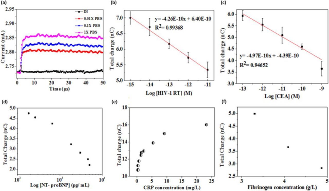
Figure 2. Characteristics of high field modulated FET biosensor (a) Effect of ionic strength on sensor response. Total charge versus protein concentration in 1X PBS for (b) HIV-1 RT detection (c) CEA detection. Total charge versus protein concentration in human serum for (d) NT-proBNP detection (e) CRP detection35 and (f) Fibrinogen detection.37
Portable FET Biosensor System for Rapid Diagnostics
This methodology entails a simplistic and direct technique to detect biological analytes in their native environment. Since FET is used to capture the biological interactions in their pristine form, additional sample processing steps are not required. This greatly simplifies the assay protocols and translates the technology toward clinical applications. A simple and robust FET packaging technology was previously developed38,39 to allow in-plane metal interconnections with the embedded FET chip. This technology uses a thermo-curable polymer substrate to embed the FET chip after which interconnects can be laid out on the same plane as the FET, in a flexible, user-friendly and application specific manner. This technology was used to design and fabricate a 'use and dispose' GaN HEMT biosensor chip, in the contours of microSD card to be mounted on a portable measurement unit (as described in Figures 3a and 3b. A simple capillary channel was used to bring the sample solution to the sensing area.39 In a previous study a portable FET biosensor system was realized and potential applications in cardiovascular disease (CVD) risk assessment was demonstrated by detecting cardiac troponin I directly in 1X PBS (with added BSA) and human serum samples.40 The results are shown in Figure 3c. The feasibility of antibody-based and aptamer-based cardiac troponin I sensors is studied in detail. The study uses current gain as the sensor signal which is the difference in drain current before and after gate pulse voltage is applied. This is relatively a more stable index than the absolute drain current because thermal variations or external impedance loading may cause drifting of absolute drain current. Another important CVD biomarker besides troponin I is brain natriuretic peptide (BNP) which is routinely used in clinical CVD diagnosis. We have demonstrated that a rapid diagnostic assay can be performed using the GaN HEMT biosensor system to detect BNP in human serum, the results of which are depicted in Figure 3d. These results demonstrate another significant aspect of this methodology: selectivity. Purified BNP samples were spiked into human serum with undetectable levels of BNP. This experiment serves as a positive control because the sensor signal changes in a BNP concentration dependent manner, even though various other proteins that are abundant in human serum are present in the test background. This can be partly attributed to, as explained previously, the very limited sample incubation period of 5 minutes during which non-specific interactions are minimal. In a microscale point of view, specific and non-specific binding of biomolecules may be viewed as electrostatic interactions at the sensor/solution interface and bulk electrolyte, respectively. When the receptor binds with the target protein, the strong electrostatic interactions create charge redistributions within the local region of the EDL which is translated as change in FET drain current. However, the weak interactions of background proteins which form the solution bulk, do not have strong binding with the receptor immobilized on the sensor surface, due to which the sensor signal does not change significantly. This is demonstrated experimentally by testing various serum samples obtained from different patients35,40 on the sensor surface without receptor. Since there are no strong interactions at the local regions of the EDL on the sensor surface, the sensor signal remains relatively constant for various serum samples, depicting the physical phenomenon of strong electrostatic interactions at the interface.
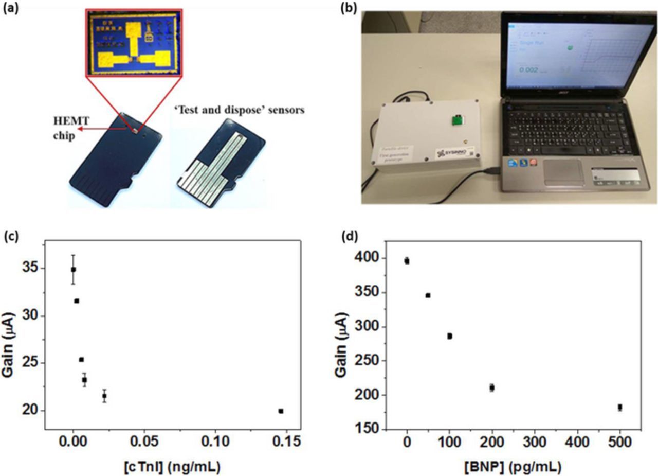
Figure 3. Portable biosensor system for rapid CVD diagnostics (a) Microfabricated FET chip in the form of microSD card (b) Portable sensor measurement unit with chip reader. Current gain versus protein concentration in human serum for (c) cTnI detection40 and (d) BNP detection.
The Mechanism of Detection Beyond Debye Length
Several studies using various protein biomarkers demonstrated that indeed, the high field gated FET biosensors can detect biomolecules in high ionic strength solutions without the hindrance of charge screening effects. However, the fundamental mechanism that propels the detection in high salt environment needs to be explored in detail. In our sensor structure, the conductivity of FET channel is not merely modulated by the ions present in the test solution. Apart from being an ion gated FET sensor, it is also modulated by the high electric field applied across the test solution. The separated gate electrode is biased with a gate voltage, which then drops across the test solution. When the electric field creates a potential gradient across the solution, EDL is formed on gate electrode and channel interfaces, which sets up a solution capacitance. This modulates the channel conductivity. To grasp a comprehensive understanding of the methodology, we need to find out the dependency of sensor signal on the applied field. It is in fact, the gating mechanism that differentiates the unique sensor from the traditional FET biosensors.
By varying the applied gate bias or the gap between the gate electrode and the channel, we can modulate the electric field across the test solution. The difference between traditional FET sensor and the present sensing structure which leads to increased sensitivity in high ionic strength is detailed in this section. Figure 4 shows the change in current gain for different electric field applied across the solution. Figure 4a illustrates the structure of the sensor which is used to vary the gaps between the openings on the gate electrode and transistor channel. The openings on the in-plane gate electrode are positioned at fixed gaps away from the transistor channel, using photolithography, as shown in Figure 4a. In this way, different electric fields can be applied across the test solution. All the openings on the gate electrode have the same area, i.e., 100 × 120 μm2 and transistor channel opening is 10 × 60 μm2. The distance between the gate electrode and the channel, or simply the gaps are 65, 1000, 5000, 10000 and 15000 μm. Figure 4b shows the change in current gain with increasing gap and increasing Vg. When Vg is increased the current gain increases, as the potential across the test solution and thereby, the transistor dielectric is increased. Similarly, when the gap between gate electrode and channel is increased, current gain decreases. In other words, when the electric field strength applied across the test solution increases, current gain increases and vice versa. However, the change in current gain saturates after a certain gap and does not vary considerably when gap is further increased. In other words, the slope or sensitivity does not change significantly after the saturation point. Therefore, we can define two regions of device operation: linear and saturation regions or high field and low field operations. In linear/high field operation, the gap between gate electrode and channel is sufficiently small such that the applied field can effectively modulate the channel conductivity. In other words, the change in current gain is linearly dependent on the gap between the gate electrode and channel. But in saturation/low field operation, the applied field no longer modulates the channel conductivity, or it assumes a low and constant value which is not modulated by further changing the gap. A quick comparison between linear and saturation regions of device operation reveals that the traditional FET sensor operates in the saturation/low field region, because the reference electrode is either grounded or maintained at very large (arbitrarily large), uncontrolled distance away from the transistor channel. Thus, the potential gradient generated (if any) across the test solution, between the reference electrode and the transistor channel cannot influence the conductivity. They rely on the potential difference caused by receptor-ligand interactions at the transistor gate region, which diminishes in high ionic strength solution, due to charge screening effect. On the other hand, in our sensing structure, we operate the sensor in the linear/high region, by applying a high field using the gate electrode, across the test solution. We do not need to increase the applied Vg arbitrarily high, to increase the sensitivity. The gap between gate electrode and channel is very small such that it generates a large electric field strength or potential gradient across the test solution. In this way, we can provide high field modulation without applying large voltages across solution. This type of high electric field is also employed in electrophoresis, which uses electric field gradient to drive biomolecules between two metal electrodes. In electrophoresis, the applied electric field strength is at least 1 V/cm (Jameson and Alvarez-Tostado, 1939; Holmes and Stellwagen, 1990). In our typical sensor, gate bias is applied at 1 V over a gap of 65 μm which generates very high electric field strength of 154 V/cm. If 1 V/cm is considered to the critical field strength, with reference to electrophoresis, it can be seen that our sensor in fact operates in the linear/high field region, where the applied high field can modulate the channel conductivity effectively. From Figure 4b, we can see that the linear region extends till 10000 μm after which the current gain gets saturated. Therefore, the critical field strength in this device structure is 1 V/cm.
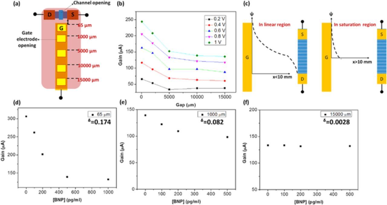
Figure 4. Effect of varying electric field in sensing characteristics (a) Varying gap experiment configuration (b) Gain response versus gap (c) Potential distribution in linear and saturation regions (d) through (f) BNP sensing characteristics in 65 μm, 1000 μm and 15000 μm, respectively.
We have established that at higher electric field strength, sensor signal is higher. This is shown to be relevant to the existence of potential gradient across the solution, similar to the working principle of electrophoresis. The physical phenomenon that enables high sensitivity detection in linear region can be envisioned as extension of the potential gradient across the solution. The potential gradient across the solution in linear and saturation regions of device operation are illustrated in Figure 4c. In high field/linear region, the electric field across the solution is non-zero while in low field/saturation region, the applied potential quickly decays through distance from point of application.
To confirm that sensitivity is indeed enhanced by the high field modulation, we performed BNP detection in 1X PBS with added BSA, under 3 different field strengths, by varying the gap between the gate electrode and channel. The gaps were: 65, 1000, and 10000 μm, with an applied Vg of 1 V. The results of BNP detection, modulated by different electric field are depicted in Figures 4d through 4f. Figure 4d represents the sensor response at 65 μm gap, 4e at 1000 μm gap and 4f at 15000 μm gap. Sensitivity of the FET biosensor can be evaluated by change in signal (current gain) over the change in BNP concentration. As seen in the figures, when the gap increases, or electric field decreases, the sensitivity of protein detection decreases. Since the saturation point is around 10000 μm (at an applied field of 1 V/cm), it is not surprising that even though antibody may bind with BNP in the gate electrode, there is no significant change in sensor signal at 15000 μm, where the electric field is less than the critical field. The test results obtained with 15000 μm gap, uses the same bias conditions as the traditional FET biosensors, in which the applied field strength is lesser than the critical field and hence, face poor sensitivity in high ionic strength solution, limited by charge screening effect.
The applied gate voltage drops across the solution and the transistor dielectric, as shown in Equation 2,
![Equation ([2])](https://content.cld.iop.org/journals/2162-8777/7/7/Q3032/revision1/d0002.gif)
The EDL created at the gate electrode and channel interfaces set up a solution capacitance Cs, which modulates the transistor dielectric capacitance Cd. If the capacitances are considered in series connection, we can represent Equations 2 in terms of capacitances across the sensor, following Equations 3 and 4,
![Equation ([3])](https://content.cld.iop.org/journals/2162-8777/7/7/Q3032/revision1/d0003.gif)
Where Z is the total impedance in the circuit and j and ω are complex parameter and angular frequency respectively.
![Equation ([4])](https://content.cld.iop.org/journals/2162-8777/7/7/Q3032/revision1/d0004.gif)
Where Cs and Cd are solution and transistor dielectric capacitances, respectively.
Therefore, following Equation 2, potential drop across the transistor dielectric Vd can be expressed as in Equation 5,
![Equation ([5])](https://content.cld.iop.org/journals/2162-8777/7/7/Q3032/revision1/d0005.gif)
Therefore, when Cs increases, the potential drop across the transistor dielectric increases.
From the FET model, the sensor gain in linear region can be expressed as in Equation 6,
![Equation ([6])](https://content.cld.iop.org/journals/2162-8777/7/7/Q3032/revision1/d0006.gif)
Since, ΔVg represents the effective change in potential across the HEMT sensor as a result of biological interactions in the test solution, it is equivalent to the potential drop across the transistor dielectric ΔVd which modulates the drain current of FET. Therefore Equation 7 can be re-written as,
![Equation ([7])](https://content.cld.iop.org/journals/2162-8777/7/7/Q3032/revision1/d0007.gif)
Equation 7 describes the quantitative model for EDL gated FET biosensor. When the solution capacitance Cs is increased arbitrarily large, current gain assumes a maximum value. This increase in Cs can be brought upon by varying the ionic strength of the test solution, surface functionalization and receptor-ligand binding. Also, when electric field applied at the gate electrode is increased, either by increasing the amplitude of Vg or decreasing the gap between the gate electrode and channel, Cs increases accordingly, yielding enhanced sensitivity. Similarly, when the sensor is operated in the saturation/low field region, like traditional FET biosensors, Cs assumes a lower value because the electric field applied at the gate electrode does not modulate the channel conductivity. This means that, following Equation 7, we can design an optimal sensor structure with which we can enhance the sensitivity of the assay without having to increase the bias amplitude or change the ionic/biomolecular composition of the test sample.
Since our sensor is high field modulated, it is worthwhile to examine the fundamental principles that describe potential and charge distribution in our sensor. Traditionally, Grahame equation, shown here in Equation 8, is used to depict the relationship between surface potential and surface charge density on a planar surface.
![Equation ([8])](https://content.cld.iop.org/journals/2162-8777/7/7/Q3032/revision1/d0008.gif)
Where σ, ψ0, ɛr, ɛ0 and n are surface charge density, surface potential, relative permittivity, permittivity in vacuum, and electrolyte concentration in bulk solution, respectively. This means that for higher applied Vg, more charge density is accumulated on the gate electrode and hence the transistor dielectric, which increases the potential drop across the transistor dielectric and hence the channel conductivity increases. This is illustrated in our results in Figure 4. However, the dependence of sensor signal on the gap between the gate electrode and channel, cannot be described by Grahame equation as it does not describe the dependence of potential on distance from point of application. This effect is explained with non-linear Poisson-Boltzmann equation, denoted here as Equation 9, from which Grahame equation is derived.
![Equation ([9])](https://content.cld.iop.org/journals/2162-8777/7/7/Q3032/revision1/d0009.gif)
The boundary conditions of Poisson-Boltzmann equation can be described as
![Equation ([10])](https://content.cld.iop.org/journals/2162-8777/7/7/Q3032/revision1/d0010.gif)
![Equation ([11])](https://content.cld.iop.org/journals/2162-8777/7/7/Q3032/revision1/d0011.gif)
In traditional FET biosensors, where the distance between reference electrode and channel is arbitrarily large, the potential applied at the reference electrode does not modulate the channel conductivity, because the potential follows the boundary conditions denoted in Equation 11, i.e., when the gap is very large, the potential decays to zero. On the other hand, in our sensor which is typically operated in the linear region, the potential gradient across the solution is non-zero. The boundary conditions described in Equation 11 does not represent the scenario in our sensor, because the gap between the gate electrode (where voltage is applied) and channel is very short, which leads to the existence of a potential gradient across solution (as shown in Figure 4c). Although in solution which acts as the dielectric in our sensor, the electric field is not uniformly distributed like the case of solid capacitor, the non-linear potential gradient is sufficient to detect target analytes beyond the Debye length. Therefore, in high electric field, the potential gradient extends further than what is described by the solution of Poisson-Boltzmann equation, which enables us to detect protein beyond the Debye length. This model elucidates the principle of enhanced sensitivity of EDL FET biosensors in high ionic strength solutions such as 1X PBS and whole blood.
DNA/miRNA Sensing and Selectivity Characteristics
FET biosensors can effectively transduce the immunological reactions due to the specific electrostatic interaction between antibody-antigen. Similarly, molecular recognition also involves hydrogen bonding, which binds two strands of DNA. Thus, we can design FET biosensors to detect DNA or RNA from the test solution as well. Several Si nanowire-based FET sensors have used a complementary probe DNA to target specific DNA sequences in the solution.23 In a previous study, GaN HEMT sensor was functionalized with DNA probe to target specific DNA molecules via the property of DNA complementarity.41 The target sequence was the DNA strand of micro RNA (miRNA) that has pathophysiological relevance in CVD risk assessment. It was then demonstrated that in similar manner, a single stranded DNA probe can capture the target miRNA sequences directly in high salt concentration buffer. Figure 5a through 5c demonstrates the DNA/miRNA sensing characteristics of miR-126, miR-21 and miR-208a sequences. Current gain of the HEMT sensor increases as target DNA/miRNA concentration increases. Hybridization of the DNA probe and the target miRNA is carried out at temperatures slightly below the melting temperature (Tm) of the target to exclude mismatched DNA/RNA molecules. In this way, we can differentiate perfectly matched and mismatched DNA sequences due to their different binding ratios which are resulting from their different dissociation constants. Thus, selectivity of sensor toward target DNA/RNA molecules was demonstrated.41 The study reveals encouraging results in DNA/RNA sensing which often suffer from poor limit of detection and selectivity. While using clinical samples, if washing procedure is carried out to remove the unbound DNA/RNA away from sensor surface, the sensing characteristics can be further improved because the HEMT sensor can distinguish partial from full complementarity.
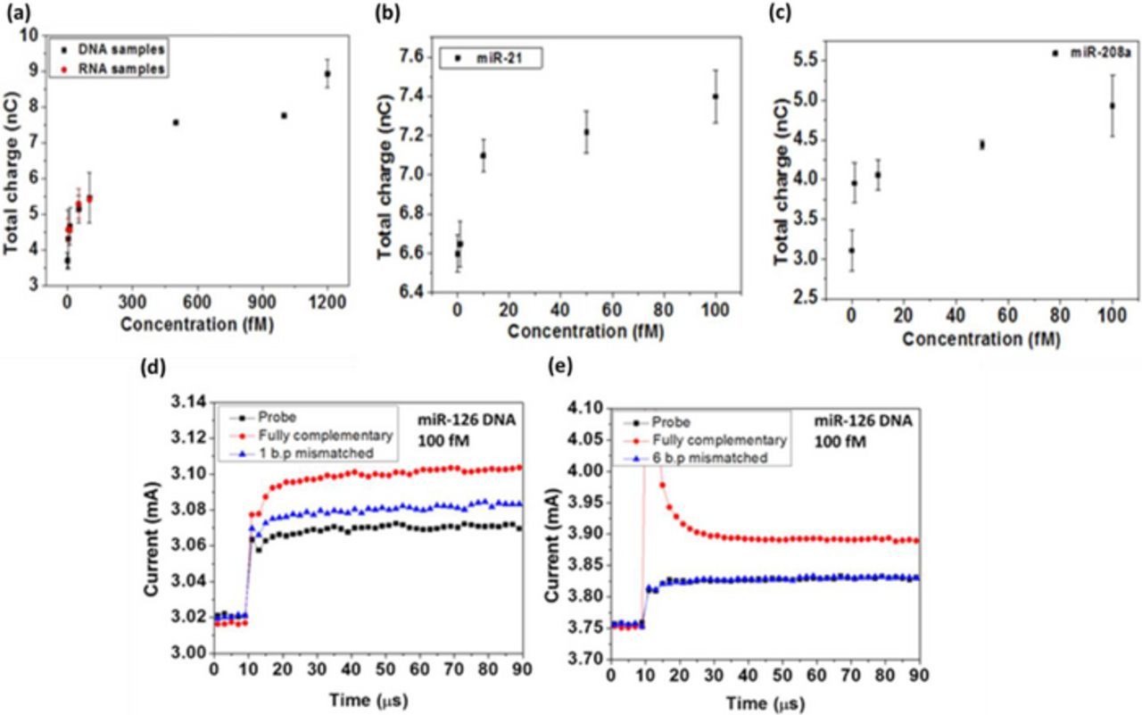
Figure 5. Total charge versus concentration for (a) miR-126 (b) miR-21 and (c) miR-208a detection. Selectivity response elucidated via testing (d) 1 base pair mismatched DNA and (e) 6 base pairs mismatched DNA.41
Whole Cell Sensing for Early Cancer Diagnosis
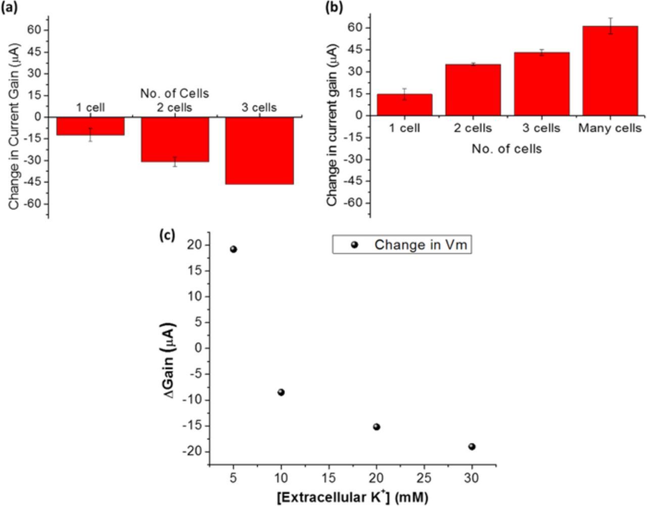
Apart from basic biomolecules such as proteins and DNA, the platform of high field gated FET biosensor can also be used to target the basic building blocks of life, cells. Since cellular plasma membrane has various transmembrane proteins and receptor molecules attached, whole cell sensing was carried out by capturing cells using antibody that specifically binds with plasma membrane receptors. To make cell-based sensor systems more robust, an aptamer specific to the target cell line can be developed to capture and analyze whole cells.42 In a previous study, we have demonstrated that EDL gated HEMT sensor can be used to detect and count the number of cells captured on the sensor surface.43 Aptamer specific to circulating tumor cells (CTCs) was screened by Hung et al.42 The separated gate electrode is functionalized with the aptamer which captures CTCs from the test solution. Majorly two distinct test solutions were used to suspend CTCs: 1X PBS and cell culture medium. The current gain of the sensor decreases as number of cells captured increases, when cells are suspended in 1X PBS, as depicted in Figure 6a. On the other hand, gain increases as number of cells captured increases, while cell culture medium is used as the test solution (seen in Figure 6b). This indicated that the solution capacitance decreases or increases with respect to the baseline, based on extracellular stimuli to the cells captured on the sensor. This was found to be relevant to the changes in transmembrane potential (Vm) of cells when the extracellular constituents such as ionic composition is varied.43 The findings were used to design experiments to induce changes in the Vm of captured cells by modulating the extracellular KCl concentration.44 KCl induced depolarizations of cell is a commonly used method to calibrate potentiometric probes.45 In our study we increased the KCl concentration of the test medium in steps and observed the electrical response from the sensor with captured CTCs. The increasing KCl concentration in extracellular environment depolarized the cell, which resulted in decreasing current gain level with respect to the baseline, as seen in Figure 6c. In this method, we demonstrated that our EDL gated HEMT biosensor platform can indeed be used to monitor transmembrane potential changes in native electrolyte concentrations.
A more detailed study on the mechanism of whole cell sensing and monitoring bioelectric signature was elucidated in a previous work.44 In earlier sections, we showed that our sensor can indeed detect biological targets in aqueous solutions such as 1X PBS and serum beyond the Debye length. However, a quantitative analysis was required to determine the extent to which the effects of charge screening is reduced or simply, by how much is Debye length apparently increased. In another work, we conducted experiments to capture and detect CTCs using GaN HEMT sensor, at close proximity and far away from the sensor surface. The test results are depicted in Figure 7. Figures 7a and 7b demonstrate cell capture and detection when the aptamer is directly immobilized on the gate electrode. Figures 7c and 7d show the results of cell capture and detection when the aptamer was immobilized on a duplex DNA spacer which created a gap in the z direction, between the captured cell and the sensor surface. The sensitivity significantly reduced when cells were captured at distance far away from the sensor surface. An estimation of the distance in the latter case was provided to be ∼7 nm. This indicates that using our sensor methodology, we can at least extend the Debye length one order higher in magnitude. This can be further improved upon by optimizing the applied field or modulating the gap between the gate electrode and FET channel. This study also suggests that electrostatic interactions at the close proximity of the sensor surface contribute toward sensor signal while weaker interactions that are farther away from the surface, does not influence the sensor response. It is also proven experimentally by testing cells afloat on the gate electrode area without aptamer to bind with the cells. In this case, as seen in Figures 7e and 7f, the sensor signal does not change significantly due to the presence of unbound/weakly bound cell. This is an important result as it transcends the sensing platform toward biomarker detection in whole blood.
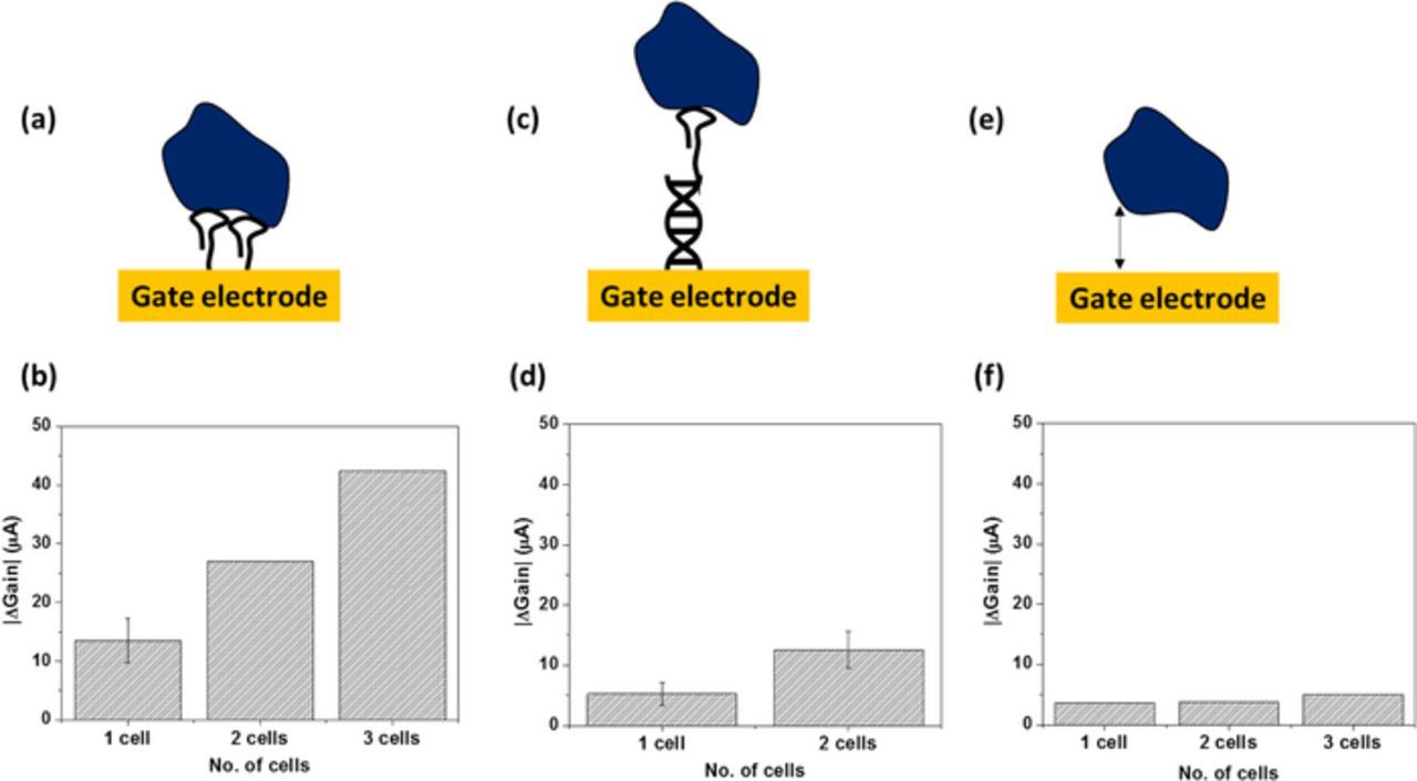
Figure 7. Cell proximity effect (a), (b) Cells captured at the sensor surface (c), (d) cells captured far away from the sensor surface (e), (f) cells allowed to stay afloat on sensor without receptor.44
Whole Blood Diagnostics
In the previous section, we have seen that cells that are not in the close proximity of the sensor surface do not change the sensor signal. Following this, it can be assumed that various cells present in human blood will not cause significant impedance to signal transduction while using our sensor methodology. This idea is demonstrated here by testing for D-dimer directly in whole blood. D-dimer is an important hemostasis marker and thus plays a major role in CVD pathophysiology. To improve sensing capabilities, the device structure was modified in to an extended gate design (shown in Figure 8a). Discrete MOSFET can be used for signal transduction in this strategy. The gate electrode was placed on a separate chip and paired with another electrode which was connected to the MOSFET gate metal. The pattern of two gold electrodes separated by a short distance was arrayed on the chip which provided multiple reaction sites on a single chip. In this method, the test solution does not touch the FET which is placed on a separate PCB. This implies that we have the flexibility to use any type of FET for signal transduction, such as Si nanostructure based or 2D nanomaterial based FETs instead of discrete MOSFETs. Antibody to D-dimer was immobilized on the extended gate electrode on the separate chip. The surface functionalization can be verified electrically, as shown in Figure 8b. The sensor signal is denoted as the difference in current gain of the electrodes with and without antibody. In this way, the electrode pairs without antibody (bare gold electrode) gives the information about the test background and the electrode pairs with antibody transduces the binding of target protein. The sensor response curve for D-dimer detection in 1X PBS (with added BSA) is shown in Figure 8c. The current gain decreases with increasing D-dimer concentration. As means of positive control, purified D-dimer was also spiked in whole blood with undetectable D-dimer levels. A single drop of whole blood sample spiked with D-dimer was dropped and the sensor was held in an inverted position during the sample incubation period of 5 minutes. This gravitationally separated the blood cells from plasma, without any external actuation. Electrical measurements were then carried out, the results of which are depicted in Figure 8d. Since the blood was treated with anti-coagulants, the blood cells did not form dense clots, but gently precipitated along the gravitational force. The current gain of the sensor decreased as D-dimer concentration increased. These results demonstrate a promising future for this technology in point of care diagnostics or home care medical devices.

Figure 8. D-dimer detection in whole blood (a) Schematics of extended gate FET sensor (b) Anti-D-dimer immobilization (c), (d) Change in current gain versus concentration of D-dimer in 1X PBS and whole blood, respectively.
Electrical Characterization of Biological Tissue
Apart from biomolecules and assembly of macromolecules, our sensor methodology can be applied to the identification of biological tissue as well. This is intuitive as tissue is a collection of cells that are embedded in a biomolecule rich extracellular matrix (ECM). GaN HEMT sensor was used for analyzing various types of porcine tissue. When the tissue sample is sandwiched between the gate electrode and the transistor channel (as shown in Figure 9a), under the application of gate voltage, the applied field drops across the tissue sample and the characteristics pertaining to the type of tissue can be analyzed electrically. As seen from Figure 9b, fat and skeletal muscle tissues generated varied responses from the sensor. Fat tissue displayed a slower rise time and lower gain compared to the muscle tissue. This can be attributed to the low water content in fat tissue.46,47 The experiment was repeated several times with different sections of tissue samples to obtain statistical average, displayed in Figure 9c. This showed that we can easily distinguish different types of tissue based on their electrical impedance properties. This idea can be used for specific biomedical applications in developing surgical assistance tools. Surgeons often rely on experience or very deep understanding of human anatomy to prevent surgical errors involving blood vessel rupture. We here demonstrate that our GaN HEMT biosensor platform can distinguish between the renal blood vessel and the muscular tissue surrounding the vessel, as seen in Figure 9d. Statistical average from multiple testing is depicted in Figure 9d. The vessel and muscle tissues may be differentiated either current gain level or difference in their rise times (as seen in Figure 9e). Another approach to enhance the sensing and distinguishing capabilities is to use a biphasic pulse input as gate voltage, applied to the gate electrode. The biphasic pulse propagates deeper into the tissue, generating larger signal separation for various tissue types, as seen in Figure 9f. In this method, we can clearly differentiate renal vessel, musculature around the vessel and porcine kidney tissue. Similar principle of operation may also be used to identify cancerous tissues, as malignancy will drastically change the cell-cell junctions, creating a difference in electrical impedance.48

Figure 9. Identification of biological tissue (a) Real images of different biological tissue samples on sensor surface (b), (c) Sensor response for fat and skeletal muscle tissues (d), (e) Sensor response for renal vessel and the muscle around it (f) Sensor response to biphasic pulsed input.
Conclusions
In this part review, part original research, we have detailed the design, fabrication and characterization of FET based biosensors for biomedical applications. Major FET sensing structures developed to tackle charge screening effect in aqueous solutions are reported and in-depth analysis of high field modulated FET biosensor is carried out. The mechanism of detection beyond Debye length in high ionic strength environment is studied. Several biomedical applications using high field gated FET biosensors are demonstrated such as direct protein detection in 1X PBS/serum/whole blood, DNA/RNA detection in 1X PBS, whole cell sensing and enumeration in physiological media, monitoring transmembrane potential changes using FET biosensors and electrical characterization of tissues. The simplicity and robustness of the sensor structure and the integrated biosensor system allows for ease of device operation for the end user and a low cost yet reliable portable biomedical sensor for clinical applications.
ORCID
Yu-Lin Wang 0000-0002-4791-936X