
Abstract
Porous anodic alumina (PAA) films, formed by anodic oxidation in acidic solutions, contain hexagonal arrays of parallel cylindrical pores, with pore diameter and spacing between ten and several hundred nanometers. Simulations were developed for the electrical potential distribution in the film during steady-state PAA growth, and used to calculate the rates of metal-film and film-solution interface motion. In particular, a model using the assumption of no space charge (Laplace's equation) and one based on the current continuity equation, in each case coupled with high-field ionic conduction, were evaluated with respect to the requirement that the interface profiles are time invariant. Laplace's equation, on which prior simulations of PAA growth were based, yielded unrealistic behavior with highly nonuniform interface motion, suggesting the presence of significant space charge. In contrast, interface motion predicted by the current continuity equation was uniform, except near convex ridges on the metal-film interface between pores. To fully rationalize the steady-state PAA geometry, phenomena other than conduction should be considered, which are able to provide inhibition of the oxidation rate on these ridges.
Export citation and abstract BibTeX RIS
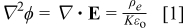
Porous anodic alumina (PAA) films are formed by anodic polarization of aluminum in baths of, for example, sulfuric, oxalic, or phosphoric acid.1–3 Recently developed procedures to grow films with highly ordered geometry have led to considerable interest in the use of the porous alumina films as templates for fabrication of devices for magnetic, optical, and other applications.6, 7 Porous oxides with similar morphologies have been grown on other metals such as Ti and Ta.8, 9 The morphology of PAA consists of evenly spaced and mutually parallel pores, oriented perpendicular to the metal/film interface. Viewed from the top, the pores form a hexagonal array. The interpore distance ranges from 10 to  , and along with the pore diameter may be controlled by the film formation voltage and the acid type. The PAA film geometry is shown in Fig. 1, in both plan and cross-sectional views. As shown in Fig. 1b, there is a barrier oxide layer at the pore base, with a thickness roughly half of the pore-pore distance; both interfaces of the barrier layer have a characteristic scalloped shape. Anodizing experiments are characterized by initial transients, followed by a steady state in which the pore diameter and spacing and barrier layer thickness remain constant with time, while new oxide accumulates in the pore walls.
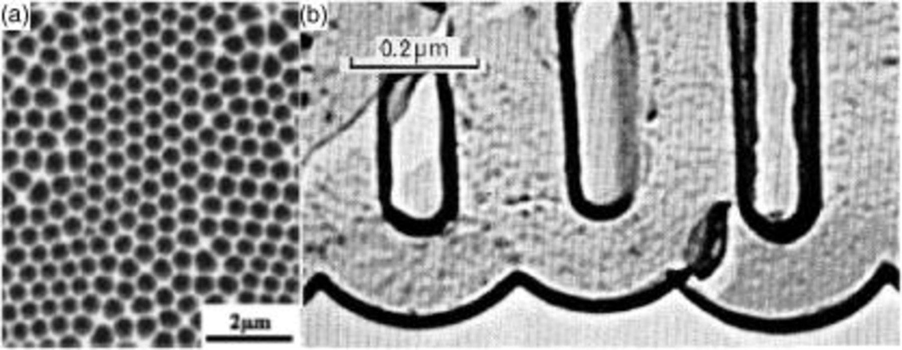
Figure 1. (a) Scanning electron microscopy image of the metal oxide interface after removal of the porous alumina (from Ref. 4, reprinted with permission). (b) Replica transmission electron micrograph of an anodic film formed in phosphoric acid [from Ref. 5, J. P. O'Sullivan and G. C. Wood, "The morphology and mechanism of formation of porous anodic films on aluminum," Proc. Roy Soc. London A, Vol. 317, plate facing page 514, Fig. 1a (1970); reprinted with permission].
There is yet no generally accepted quantitative mechanism for porous film formation. Mechanistic insight may permit synthesis of films with new geometries or based on new materials. Qualitative explanations for PAA growth have been advanced based on concepts such as electric field and temperature-enhanced dissolution of the oxide at the pore bottom,5, 10 and nonuniform mechanical stress along the metal/film interface.11 Mathematical models are attractive for testing pore formation mechanisms, because they can predict the evolution of the film to the steady-state morphology, and evaluate the consistency of a mechanism with observed steady-state film geometries. Models for porous alumina have been developed based on descriptions of ion transport and interfacial reactions,12, 13 and on the coupling of interfacial reactions and transport with elastic stress and surface energy.14 These models were based on the potential distribution in the film, which determines the rates of metal oxidation at the metal/film interface, and transfer of oxygen and aluminum ions at the film/solution interface. The interfacial reaction rates dictate the rates of interface motion, and hence the evolution of film geometry. Parkhutik and Shershulsky developed equations governing interface motion, making use of the Laplace's equation, which followed from the assumption of zero space charge in the film.12 The steady-state film geometry was predicted as a function of bath pH and applied voltage. Thamida and Chang13 used Parkhutik's modeling equations, but additionally treated dynamic pore ordering during initial oxide growth. The model of Singh et al. obtained the potential distribution from Laplace's equation, and included the effects of capillary pressure and elastic stress on kinetics of interfacial reactions.12 However, the voltage drop through the oxide ranges from 10– ,11 while interfacial potential drops are much smaller, usually less than several hundred millivolts. This suggests that conduction rather than kinetics of interfacial reactions is likely to control interface motion.
Here, we present a model for the potential distribution in porous anodic alumina during steady-state film growth. Potential distributions were predicted based on either Laplace's equation (based on the assumption of no space charge) or the current continuity equation. In the model, ion transport was by high-field conduction, in which the conduction current density increases exponentially with electric field. Ebihara et al. earlier demonstrated consistency between the high-field conduction equation and steady-state current-voltage data, over a wide range of temperatures and bath compositions.15 The potential field equations were solved numerically using the finite element method. No other direct solution of the current continuity equation with high-field conduction in a two-dimensional geometry exists, to the authors' knowledge. The potential distributions were used to calculate the local rates of motion of the metal film and film solution interfaces. These predictions were evaluated with respect to the requirement of uniform interface motion (i.e., time-invariant interface profiles) during steady-state film growth. The results derived from the current continuity equation were found to be much more realistic than those from Laplace's equation. However, it was shown that neither model yielded fully uniform interface motion. We conclude that processes in addition to ionic conduction must be considered to account for the steady-state geometry of PAA films.
Model
Equations governing the potential in the oxide film
The potential distribution in the film is of fundamental importance, because it controls ionic conduction, and hence interface motion. The electric potential ϕ and electric field,  are related to the ionic space-charge density,
  , by Poisson's equation
where  is the permittivity of free space, and
  is the dielectric constant. At steady state, the species conservation equation for a charge carrying species
  in the oxide is
where  is the flux of
  , including contributions from electrical migration, diffusion, and convection. The convective velocity would arise due to choice of a reference frame which moves with the interface. The species
  include all mobile species in the film, i.e.,
  ,
,  ,
,  ,
,  ions, or corresponding "lattice" defects. Battaglia and Newman developed a model for passive films based on Eq. 1, 2, and accounting for the effects of high electric fields on transport.16 Their approach, however, cannot be used here, owing to insufficient knowledge of mobile species and their transport properties.
Simplifying assumptions are needed to obtain models for the potential distribution. One possible assumption is that, at the high electric fields approaching  in the oxide, electrical migration fluxes of aluminum and oxygen-containing ions greatly exceed the corresponding diffusion fluxes. This assumption was supported by Ebihara et al. ,15 who derived realistic current-voltage relations using a model neglecting diffusive transport. In this approach, the potential distribution obeys the steady-state current continuity equation
where  is the current density in the oxide.17 For one-dimensional film geometries, the current density depends on the field according to

where  and
and  are the field coefficient and pre-exponential current density for high-field conduction. According to the limiting behavior of
  at large and small values of
  , Eq. 4 reduces to the well-established exponential high-field conduction law at high fields, and to ohmic conduction when the field is low. However, this ohmic limit is not approached where there is appreciable anodic current in the PAA film, because typical current densities are of order
  , while values of
  are smaller by several orders of magnitude.15 Nevertheless, the hyperbolic sine dependence was used in simulations, because in the pore walls, both the current density and field strength approach zero. For use in the present model, the scalar Eq. 4 was extended to vector form
The same conduction equation was stated by Parkhutik.12 Unlike Eq. 4, Eq. 5 applies to situations where the direction of the electric field vector differs from that of the coordinate axis. Accordingly, the direction of the current density is given by the unit vector −∇ϕ∕∣∇ϕ∣ in the direction of the field. Substituting Eq. 5 into Eq. 3 yields
the form of the current continuity differential equation used in the present model.
An alternative equation governing the potential in the oxide is based on the assumption of no space charge; then, Eq. 1 simply becomes Laplace's equation, i.e.,
Equation 6, 7 become equivalent only for a planar one-dimensional film geometry (when either equation yields a uniform field), or for multidimensional geometries when the field is small (because Eq. 6 reduces to Laplace's equation). Because the application to porous anodic films falls well outside these restrictions, the potential fields predicted by the two equations should be significantly different. Because Eq. 7 has been used in previous models of PAA films,12–14 both Eq. 6, 7 were explored in this work. Note that Eq. 7 differs significantly from the current continuity equation based on the assumptions of high-field conduction and negligible diffusion. Because current continuity must be maintained in the film, acceptance of Laplace's equation implies that either or both of these assumptions are not valid; therefore, if high-field conduction is obeyed, diffusive transport must be significant. Moreover, inconsistency of Eq. 6 with Laplace's equation suggests that appreciable space charge is necessary in nonplanar films to maintain the charge balance.
Model geometry
The simulation domain was the oxide surrounding a single pore in the film. In highly ordered PAA films, the pores are parallel, circular in cross section, and arranged in a two-dimensional hexagonal lattice. We approximated the hexagonal unit cell as a circle, in order to take advantage of the resulting rotational symmetry. Cross-sectional electron micrographs indicate that the interfaces of the film at the pore bottom form approximately spherical contours (Fig. 1b).3, 5 However, close examination reveals that the film solution interface is more accurately depicted by an elliptic surface, with a minimum film thickness along the pore axis. Figure 2 shows model pore geometries, showing spherical (solid line) and elliptic (dashed line) film solution interface contours, both of which are considered in calculations.  and
and  are the radii of concentric spheres at the film solution and metal film interfaces, respectively. The metal oxide interface at the ridge top was represented as a spherical section with radius
  of 5–
of 5– , based on cross-sectional transmission electron microscopy (TEM) images.3, 5 The other geometric parameters are
  , the angle from the pore axis to the ridge-top; δ, the oxide thickness along the pore axis; and δ', the oxide thickness along the direction
  . The ratio δ'∕δ was 1.0 for the spherical film solution interface, but ranged from 1.0 to 1.05 when elliptic interfaces were considered. Because the oxide is rotationally symmetric about the pore axis, the model domain included only half of the cross section, as shown in Fig. 2. The calculations used a cylindrical coordinate system centered on the pore axis.
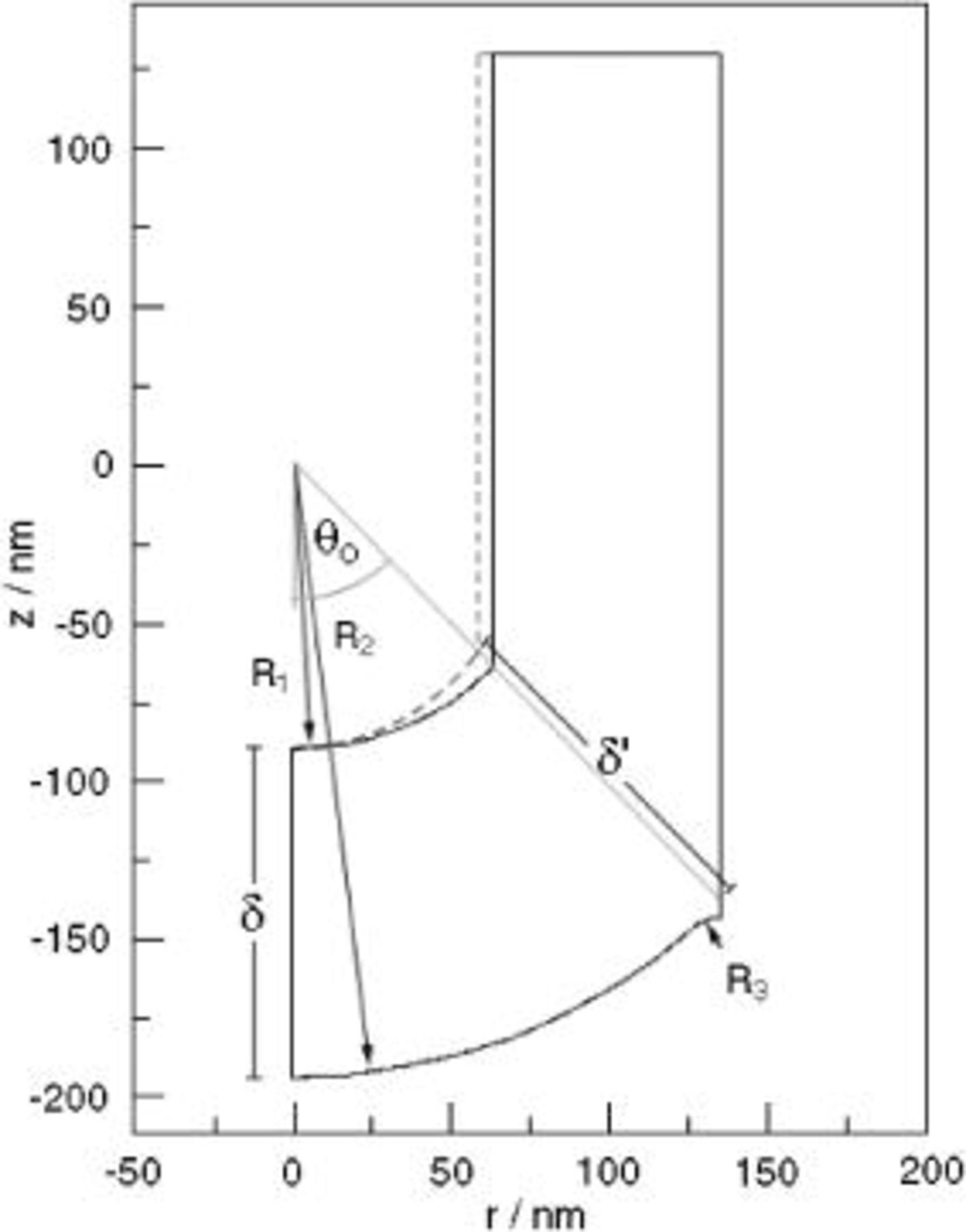
Figure 2. Outline of the model domain, representing a cross section of the porous oxide. See the text for descriptions of symbols. Dashed line indicates elliptic film solution interface profile, for δ'∕δ larger than 1.
Boundary conditions
The boundary conditions were the same whether Eq. 6 or 7 was used to simulate the potential field in the film. The potential drop in the pore solution was neglected, so that the potential just outside the electric double layer at the oxide solution interface was set to the reference value of zero. The potential at the metal film interface along the bottom of the domain was then  , the applied anodizing voltage. Because of symmetry, the boundary conditions for ϕ at the left and right vertical edges of the domain in Fig. 2 were
where  is the unit normal vector.
At the oxide solution interface, metal and oxygen-containing ions are transferred between the two phases, as depicted in Fig. 3. Following Vetter and Gorn,18 the ion-transfer reactions are modeled as independent processes driven by an interface overpotential η
where  is the interfacial potential drop and
  is the potential difference when oxygen in the film and water in solution are in equilibrium. When η is zero, the film thickness remains constant with time, because there is no net transfer of oxygen across the interface; however, because interfacial metal ion transfer is not in equilibrium, there is a steady-state current due to
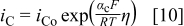
  dissolution. The Vetter-Gorn model has been validated experimentally on both iron and aluminum.19, 20 The current densities of the film solution interface reactions are given by the kinetic expressions
and
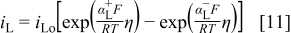
for  and
and  transfer, respectively.18 Here,
  ,
,  , and
, and  are transfer coefficients for metal and oxygen ion transfer processes. Rigorously, the potential at the film solution interface should be set to η, which depends on the interface current density
However, typical anodizing current densities of a few  , along with estimates of kinetic parameters from Ref. 20, indicate that η is less than
  . Because the applied voltage
  during PAA growth is greater than
  , the boundary condition
  was used at the film solution interface. The same interface boundary condition was used in Ref. 12, 13. The current densities
  and
and  could be determined if needed after the simulation, by first calculating
  from the potential field in the oxide, and then solving Eq. 12 for η.
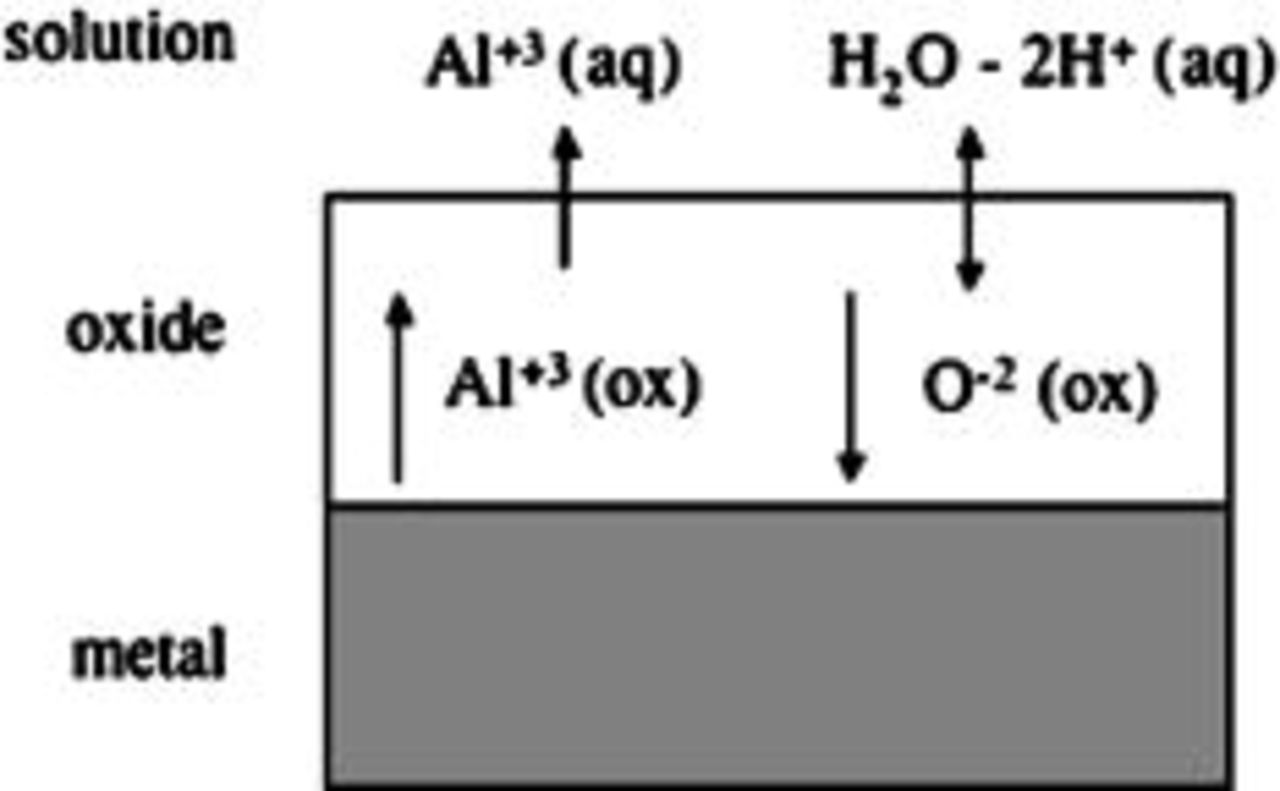
Figure 3. Schematic illustrating ionic conduction in the oxide film and ion-transfer reactions at the oxide film/solution interface.
Interface profile evolution
During steady-state growth of porous alumina films, both interfaces of the film at the pore bottom maintain the same profile. Equations for the evolution of interface profiles were developed to test whether the model was consistent with this time invariance. The velocity of the film/solution interface is determined by a balance on oxygen ions across the interface
where  is the molar concentration of the oxide,
  is the component of the conduction current density normal to the interface, and
  is the transport number for the oxygen species in the oxide. ε is the current efficiency for oxide formation at the interface
In Eq. 13 the oxide is  , although analogous equations could easily be written for other assumed stoichiometries. The left side of Eq. 13 is the net rate of removal of oxygen from the interface, the first term on the right represents the
  migration flux into the oxide, and the second term on the right is the rate of
  formation from water in solution. The interfacial velocity normal to the interface from Eq. 13 is
The normal velocity at the metal film interface is also based on an oxygen balance, which in this case includes only the arrival of  ions by migration across the film
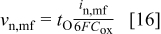
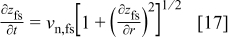
The time derivative of the film/solution interface profile,  is related to the normal velocity by12
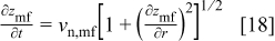
and the analogous equation for the metal/film interface is
In calculations of  , the current efficiency ε was approximated as a constant, independent of position. This assumption is supported by Fig. 4, which shows a calculation of the current efficiency at pH 1.0, based on kinetic parameters estimated from the measurements of Valand and Heusler.20 The figure shows that ε depends fairly weakly on interface current density, as it is an approximately linear function of log
  .
.
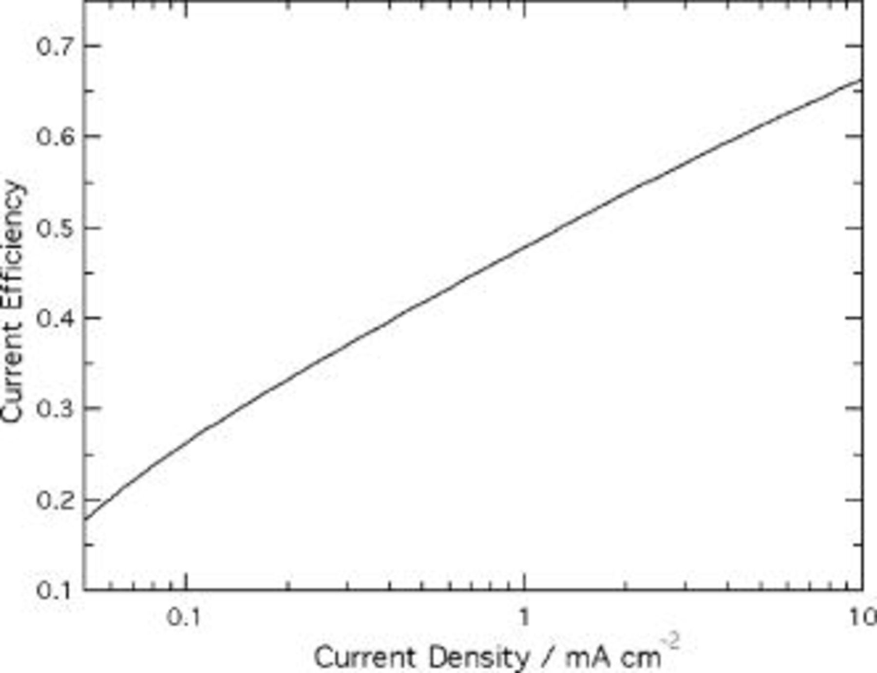
Figure 4. Current efficiency for oxide growth at the film/solution interface vs interface current density. Kinetic parameters for ion-transfer reactions were estimated using experimental data from Ref. 20 extrapolated to pH 1.0:  ,
,  ;
;  ,
,  ,
,  .
.
The interface velocity expressions in Eq. 15, 16 differ conceptually from those used previously. Parkhutik and Shershulsky's model (and later that of Thamida and Chang) used an expression for the film/solution interface velocity based on field-assisted dissolution of film material.12, 13 In Parkhutik's model, the motion of the solution interface at the pore bottoms toward the bulk metal is by oxide dissolution, while in ours it is by combined  dissolution and
  conduction into the film (the conduction path leading ultimately to the pore walls). If the recession of this interface is attributed to chemical dissolution of oxide material, it is difficult to explain how oxide accumulates in the pore walls. In fact, experiments of Siejka and co-workers, using isotopically labeled oxygen, showed that there is negligible dissolution of oxygen ions from the film at the pore base.12, 21, 22 These results are consistent with our model, in which
  ions do not dissolve into solution at the pore base, but contradicts concepts of field-assisted dissolution. A further advantage of the present model is that it follows directly from independent, general reaction kinetic expressions for the film solution interface kinetics.20 With regard to mathematical behavior, the interface velocity in both Parkutik's model and Eq. 16 is somewhat similar in that the velocity is a function of the electric field in the adjacent oxide.
Simulation procedures
Numerical computations were carried out for the steady-state oxide geometry produced by anodic oxidation in  phosphoric acid at 25°C, at an applied voltage of
  . The parameters defining the film geometry were available from detailed cross-sectional TEM measurements of films formed at these conditions.5 Referring to Fig. 2,
  ,
,  , and
, and  were 91, 195, and
  , respectively, and
  was 44°. The field coefficient
  in Eq. 6 was set to
  , an average of experimentally obtained values reported by Ebihara et al.15 The conduction current densities normal to the interfaces,
  and
and  , were calculated from the electric field magnitude at the interfaces, according to Eq. 4. A value of the conduction parameter
  was selected so that the current density at the pore axis was close to the experimental average current density,
  .3 The oxygen transport number in the film,
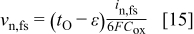
  , was taken to be 0.6 from measurements reported for anodic barrier oxide growth.23 The current efficiency, ε, was selected so that the speeds of the metal/film and film/solution interface profiles at the pore axis were equal.
Potential distributions were predicted according to both the current continuity equation (Eq. 6) and Laplace's equation (Eq. 7), and used to compute the time derivatives of the interface profiles (Eq. 17, 18). The finite element method was used to solve the partial differential equation, either Eq. 6 or 7, over the model domain. The numerical solution was accomplished using the software application FEMLAB.24 The domain was partitioned into a triangular mesh, in which the typical internode distance ranged from  near the ridge to
  in the pore wall. The nonlinear solver used an affine invariant form of the damped Newton method. The relative error was the weighted Euclidean norm, and iterations stopped when the default convergence tolerance of
  was met. In the region of the film near the pore axis, the potential distributions were found to agree precisely with one-dimensional analytical solutions of Eq. 6, 7. There was no discernible change in the simulation output when the mesh was refined by a factor of 2.
Results and Discussion
Laplace's equation
The results of the simulation assuming no space charge in the film are presented in Fig. 5, 6 and 7. Figure 5 is a contour plot showing isopotential lines, and Fig. 6 and 7 show the electric field strength and current density along the interfaces, respectively. The parameter  in Eq. 4 was set to
  , in order to produce the prescribed current density of
  at the metal/film interface on the pore axis. The current efficiency ε was slightly smaller than 0.60, the value of the oxygen transport number
  .
.
Figure 5. Contour plot of potential distribution based on Laplace's equation. The film/solution and metal/film interfaces are at 0 and  , respectively.
For small angles from the pore axis ( radian), Fig. 5 and 6 show that the field is one-dimensional, dependent only on the distance from the origin. At larger angles, the field strength and current density at the metal film interface are enhanced, because some field lines leaving the interface (perpendicular to the isopotential contours shown in Fig. 5) spread into the pore wall region. Together these field lines contribute a significant enhancement to the electric field and current density, the degree of which increases as the ridge top is approached. The field strength is a factor of 4 larger on the ridge compared to the pore axis (Fig. 6). The corresponding enhancement of current density, according to the high-field conduction equation, is 7 orders of magnitude (Fig. 7). This degree of nonuniformity is clearly unrealistic and incompatible with the requirement that the interface speed be constant. Further, Fig. 7 illustrates that Laplace's equation leads to a dramatic violation of current continuity. Near the pore axis, the current density at the solution interface exceeds that at the metal by 7 orders of magnitude. Thus, previous simulations,12, 13 which assumed no space charge in the film, are inconsistent with the experimentally validated high-field conduction law. This implies that space charge in the oxide is necessary to maintain current continuity, as discussed in the next section.
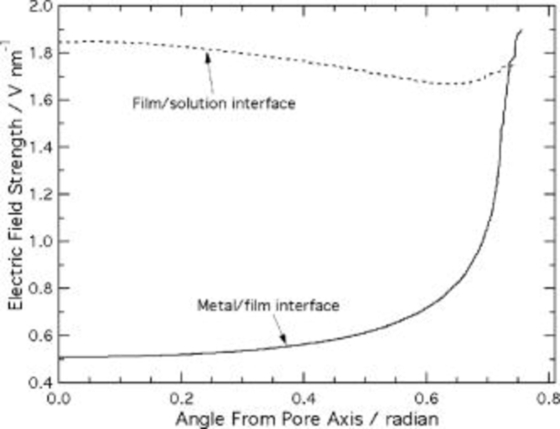
Figure 6. Electric field strength at the film interfaces, predicted using Laplace's equation.
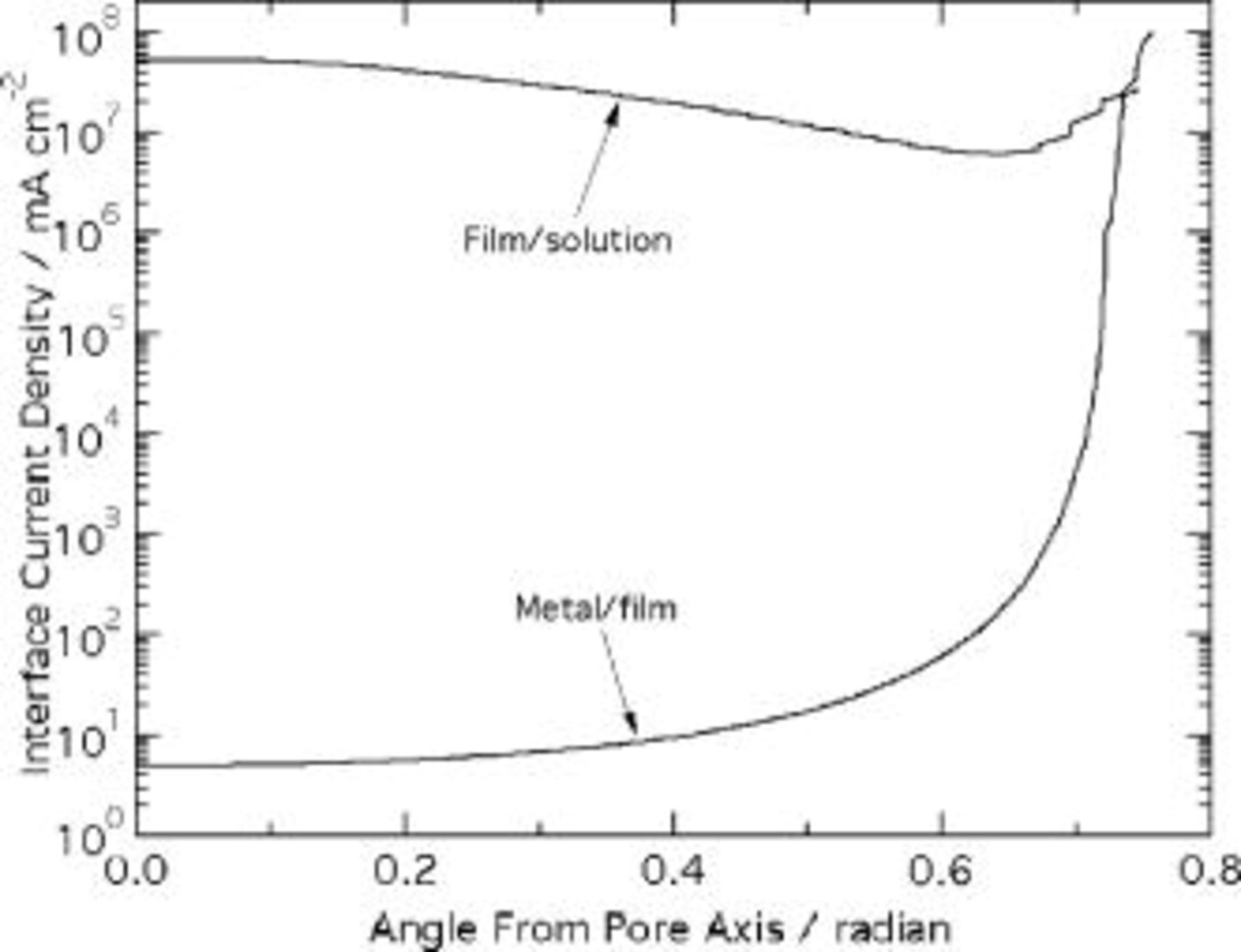
Figure 7. Interface current densities, predicted using Laplace's equation.
Current continuity equation
The results of simulations according to the current continuity equation appear in Fig. 8, 9, 10, 11 and 12. Figure 8 is a contour plot of isopotential lines, while Fig. 9 shows the interface electric field strength and Fig. 10 the time derivatives of the interface profiles, from Eq. 17, 18. The results in Fig. 8, 9 and 10 assume a spherical film solution interface; Fig. 11 depicts the effect of an elliptic film solution interface, for which  . Figure 12 shows the
  and
and  migration velocity vectors in the oxide film. The fit values of the parameters
  and ε were
  and 0.460, respectively.
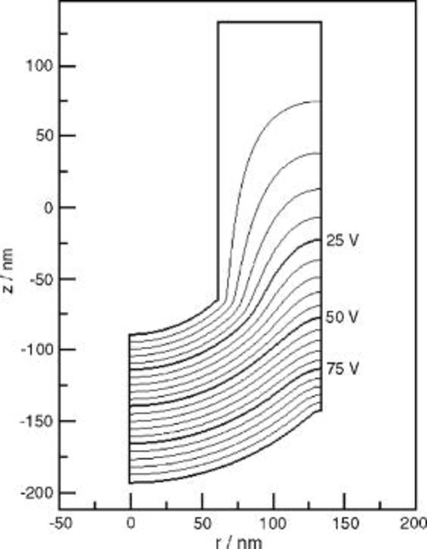
Figure 8. Contour plot of the potential distribution predicted using the current continuity equation. The film/solution and metal/film interfaces are at 0 and  , respectively.
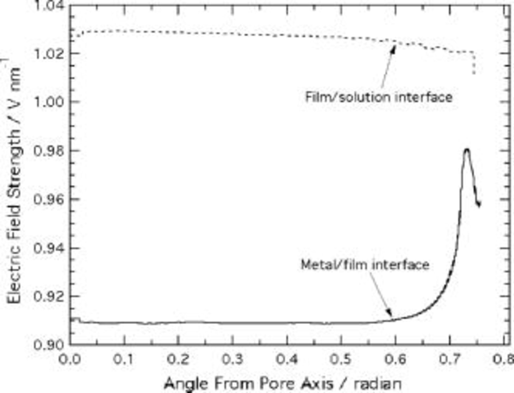
Figure 9. Electric field strength at the film interfaces, predicted using the current continuity equation.
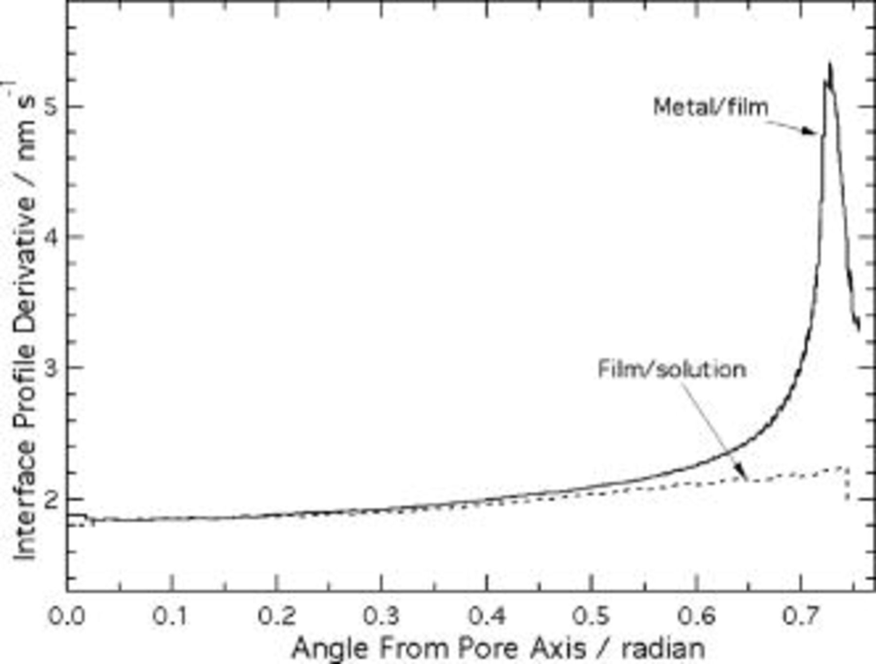
Figure 10. Time derivatives of interface height profiles, predicted using the current continuity equation.
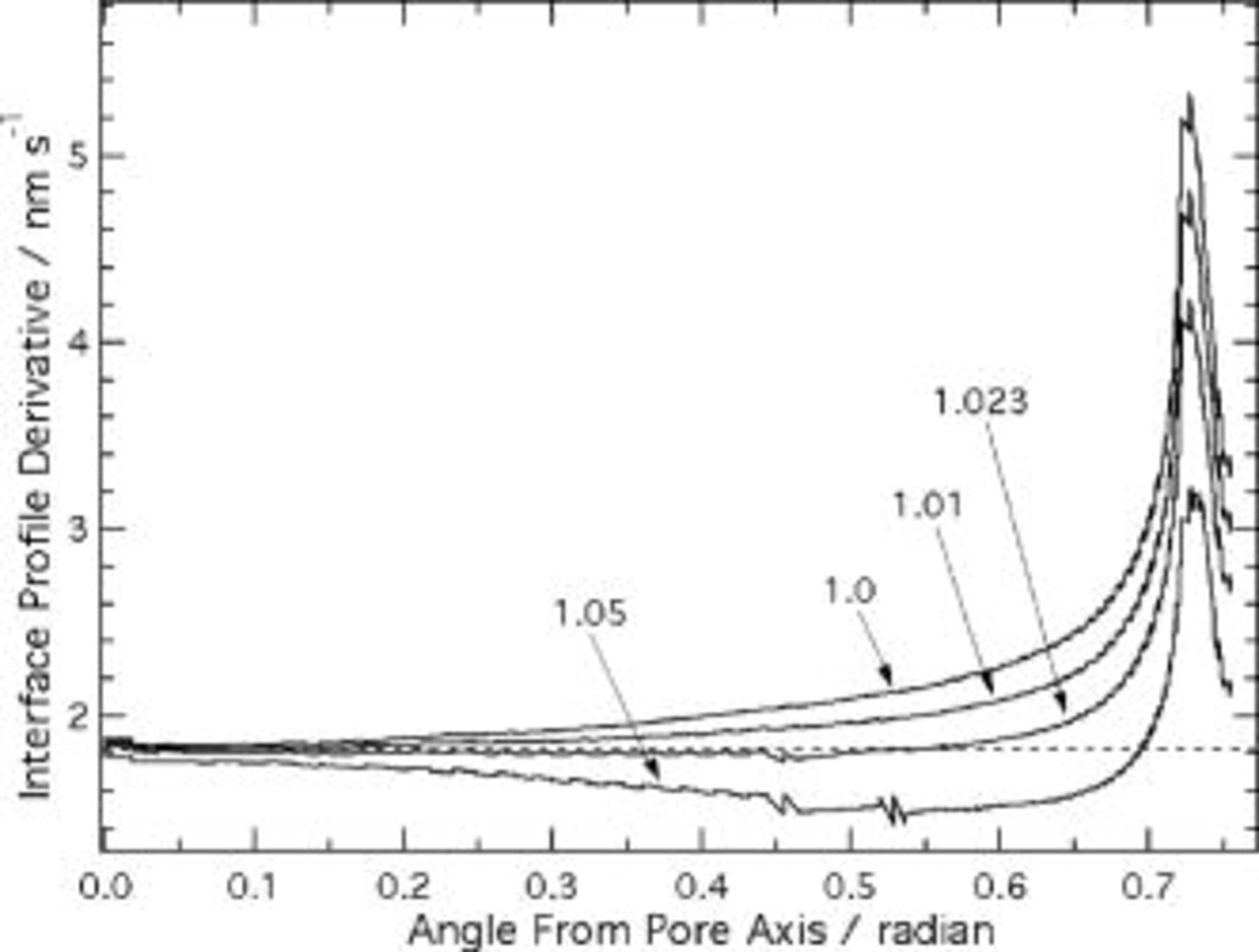
Figure 11. Effect of elliptic film/solution interface profile on time derivatives of the metal film interface height profiles, predicted using the current continuity equation. Values indicate δ'∕δ, i.e., ratio of radial distance across film at  , to that at the pore axis (see Fig. 2). The dashed line indicates the interface speed along the pore axis.
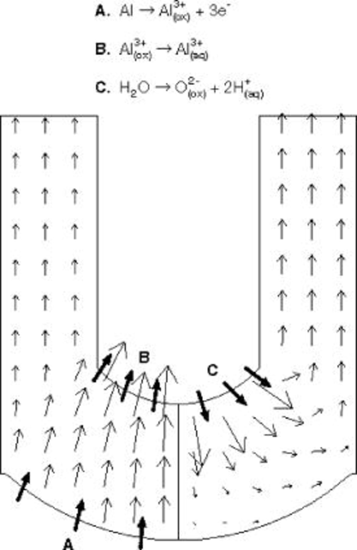
Figure 12. Ion migration velocities in the oxide film, predicted by the current continuity equation with  . Left side shows migration velocity vectors of
  ions and right side those of
  ions. Interfacial reactions are indicated by bold arrows.
Unlike the predictions of Laplace's equation, the potential distribution from the current continuity equation is uniform over much of the scalloped region. Figure 9 indicates that the electric field is effectively independent of angular position up to  radian, compared to 0.1 radian in Fig. 6. Within this region, the field differs by only 10% between the metal film and film solution interfaces. In view of the high sensitivity of the current density to electric field, only this small variation is needed to maintain the same net current at each interface. As in the Laplace's equation model, the field near the metal/film interface is locally increased on the ridge, but the degree of this enhancement is only 5%, much less than the relative increase of 270% in Fig. 6. The relatively smaller effect of the ridge curvature is due to the high sensitivity of current density to electric field. The extension of current paths emanating from the metal film interface into the pore wall region is therefore confined to the region close to the ridge
  radian), where the field enhancement is localized. The electric field at the solution interface near the ridge is not similarly increased, because the lateral spreading of the field lines is blocked by the insulating vertical boundary.
The current continuity equation requires that space charge be present in the oxide, as the potential does not satisfy Laplace's equation. Because the electric field near the pore axis is nearly constant and oriented along the axis, the space charge in this region can readily be estimated using Poisson's equation (Eq. 1). The result is
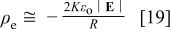
where  is the distance from the origin (Fig. 2) to a point in the film. Using
  ,
,  , and
, and  ,
,  is found to be equivalent to approximately 0.007% of the charge density due to
  ions. This small amount of charge may be accommodated by nonstoichiometry, especially because Al surface oxides in aqueous solutions contain appreciable quantities of hydrogen, at least some of which is in the form of mobile protons.25, 26 Thus, mechanisms are apparently available to adjust the space charge, in order to maintain the electric field distribution dictated by current continuity. Equation 6 then represents a physically much more realistic approximation to the potential distribution compared to Laplace's equation, which was seen to dramatically violate current continuity. The unrealistic potential distribution from Laplace's equation calls into question models of PAA films which used this equation to develop predictions of interface motion.12–14
The interface speeds predicted by the current continuity equation are nonuniform, as illustrated in Fig. 10. The metal/film interface height at the ridge decreases about 3 times more rapidly than that at the pore axis, as a result of the enhanced electric field on the ridge. In the scalloped region away from the ridge, the field and hence the interface velocities  and
and  are uniform. Thus, Eq. 17, 18 reduce to
  and
and  . The results in Fig. 10 precisely follow this
  dependence in the scalloped region. The degree of enhancement on the ridge was sensitive to the ridge radius of curvature: the interface speed on the ridge was 7.6, 5.4, and
  for
for  values of 5, 10, and
  , respectively. This effect is not caused directly by the electric field, but is instead due to the increase of the spatial derivative in Eq. 18 with increasing ridge curvature. The
  value of
  is a best estimate from cross-sectional TEM.3
As mentioned earlier, cross-sectional TEM images indicate that the film solution interface has an elliptic profile, in which the ratio δ'∕δ in Fig. 2 can be as large as 1.05.3 Because of the high sensitivity of the conduction current density to electric field, even such a small perturbation of interface profile may significantly affect the interface velocity. Figure 11 shows the effect of δ'∕δ values in the range from 1.0 to 1.05 on the derivative of the metal film interface profile. The interface speed, both near the ridge and in the scalloped region, is reduced with increasing δ'∕δ. Nearly uniform interface motion up to  radian is obtained for the ratio of 1.023, strongly suggesting that the elliptic shape of the film solution interface shape is important for controlling the uniformity of the interface speed in the scalloped region. However, even at the optimum δ'∕δ, the interface speed is locally high on the ridge, where the maximum value is about twice that on the scallop. Hence, fine adjustment of the interface geometry cannot resolve the local high interface speed on the ridge itself, where the oxidation current density is intrinsically enhanced by the convex curvature.
The transport processes and interfacial reactions contributing to PAA formation are illustrated in Fig. 12, which depicts the migration velocity vectors of  and
and  ions. The migration velocities relative to a reference frame moving with the interface are


where the first term in each equation represents the velocity in the stationary reference frame, and the second term is the correction due to the uniform reference frame velocity. The reference velocity is taken as the local metal film interface velocity at the pore axis (Eq. 16); this term represents a uniform upward pseudoconvective velocity. The figure shows that  ions formed at the metal film interface directly under the pore are dissolved at the film solution interface, while those which form beneath the pore wall are incorporated into the accumulating oxide in the wall. As the
  ions formed at the film solution interface migrate toward the metal interface, the downward component of the migration velocity diminishes due to spreading of the current vectors in the spherical-shaped film. Simultaneously, these ions move to the right with the horizontal component of the migration velocity. Eventually, the upward pseudoconvective velocity exceeds the downward component of migration, causing the
  ions to reverse direction and enter the pore wall region. Unlike models based on field-assisted dissolution, the present model accounts for both recession of the film solution interface at the pore bottom, and also accumulation of oxide in the pore walls.
Because the current continuity equation by itself does not predict a spatially uniform rate of interface motion, additional elements in the model would be needed to completely justify the time invariance of the film geometry. In particular, there should be an "inhibition" mechanism which preferentially reduces the conduction current density near the ridge. Aside from anodizing voltage, the geometry of PAA films is strongly influenced by the nature of the anodizing acid.2–4, 11, 15, 27 Significant concentrations of the acid anion are incorporated into the outer portion of the barrier oxide at the pore base.27 The possibility that incorporated anions influence conduction has been discussed.3 Preferential inhibition of conduction near the ridge could arise if there is differential penetration of anions in the ridge and scallop regions.
The one-dimensional potential distribution near the pore axis leads to a simple relationship governing the film geometry during steady-state anodizing.28 Because the interface profiles move at the same speed at steady state, the right sides of Eq. 15, 16 must be equal. Also, in the one-dimensional region, current continuity requires that  , so that
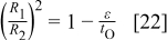
This equation implies that one condition for steady-state film growth is  , which enables the film solution interface to move in the direction of the bulk metal. When this condition is met, the rate of oxygen migration into the film ions at the film solution interface exceeds the rate of oxygen deposition. While
  is a property of the film material, ε is determined by the current density (Fig. 4), and by the pH-sensitive kinetics of the solution interface reactions. For current densities in the
  range, ε approaches 1.0 near neutral pH, explaining the difficulty of forming porous films in such solutions. The left side of Eq. 22 is equivalent to the porosity of the anodic film, indicating that the porosity is controlled by the current density and pH.
Conclusions
A numerical simulation was developed for the electrical potential distribution in PAA films during steady-state growth, in order to help identify the physical and chemical processes responsible for the unique, highly ordered film morphology. Two approximate models of the potential were considered, one according to the assumption of no space charge in the film (Laplace's equation), and the other based on the current continuity equation. In both models, the conduction current density obeyed the well-known high-field conduction law. The predicted electric field in the film was then used to calculate the velocities of the metal film and film solution interfaces. The models were evaluated with respect to the requirement that the oxide geometry is time invariant, and hence the interface motion should be uniform. Previous PAA models obtained the potential distribution from Laplace's equation.12–14
The Laplace's equation model produced interface velocities which varied by several orders of magnitude along the metal film interface, as well as a strong violation of charge conservation. This nonphysical behavior indicates that the electric field distribution differs significantly from that based on the assumption of no space charge. The models in Ref. 12–14 are therefore inconsistent with high-field ionic conduction, which has been validated experimentally. The current continuity equation produced uniform metal film interface motion in the scalloped region, while the interface speed was enhanced by a factor of 2 on the ridge. The elliptic profile of the film solution interface, consistent with cross-sectional TEM images, was necessary to obtain uniform interface motion in the scalloped region. Only a small space-charge density was needed for the current continuity equation to be satisfied, equivalent to less than 0.01% of the ion concentration in the film; thus, the current continuity equation provides a physically realistic approximation to the potential distribution. Because the high interface velocity on the ridge is an intrinsic effect of interface curvature, additional phenomena other than ionic conduction, which can provide suppression of ionic conduction near the ridge, must be considered in order to fully explain the time invariance of the PAA geometry.
Acknowledgments
Financial support was provided by St. Jude Medical Corporation.
Iowa State University assisted in meeting the publication costs of this article.