Abstract
Hot corrosion of layered machinable ceramic  coated with

 in air at 700-1000°C has been investigated by means of thermogravimetric analysis, X-ray diffraction, Raman spectroscopy, and scanning electron microscopy/energy-dispersive spectroscopy. The hot corrosion of
  was slight at low temperatures of 700 and 800°C, while
  was severely attacked by fused sodium sulfate at 900 and 1000°C. No protective scales were observed on
  and sulfur-rich layers were present at the
  substrate/scale interface. The linear hot corrosion kinetics at 800 and 900°C demonstrated that electrochemical reactions of
  with sodium sulfate at the substrate/scale interface dominated, while the parabolic kinetics at 1000°C implied that the rate-limiting step involved in the hot corrosion was the diffusion of hot corrosion medium through the scale formed. The hot corrosion behaviors were explained by a mechanism of electrochemistry coupled with basic dissolution-precipitation. © 2004 The Electrochemical Society. All rights reserved.
Export citation and abstract BibTeX RIS
Two-layered machinable ternary carbides,  and
and  in the Ti-Al-C system, are of interest as potential high-temperature structural materials due to their high specific strength and excellent high-temperature properties.1
2
in the Ti-Al-C system, are of interest as potential high-temperature structural materials due to their high specific strength and excellent high-temperature properties.1
2  and
and  exhibit good oxidation resistance due to the formation of a protective
  layer at high temperatures in spite of the low aluminum content.3
4 Moreover, in contrast to traditional carbide ceramics, they can be readily machined by both conventional tools originating from the relatively weak bonding between sheets of
layer at high temperatures in spite of the low aluminum content.3
4 Moreover, in contrast to traditional carbide ceramics, they can be readily machined by both conventional tools originating from the relatively weak bonding between sheets of  octahedra and neighboring close-packed Al atoms,5 and by electrodischarge machining because of its high electrical conductivity.1
2
octahedra and neighboring close-packed Al atoms,5 and by electrodischarge machining because of its high electrical conductivity.1
2
As a potential high-temperature structural material,  will always be exposed to the service circumstance in which hot corrosion occurs. Hot corrosion became a topic of popular interest in the late 1960s as gas turbine engines of military aircraft suffered severe corrosion during the Vietnam conflict when operating over seawater.6 Metallographic inspection of failed parts often showed sulfides of nickel and chromium, so the mechanism was initially called sulfidation. However, studies by Goebel and Pettit7 and by Bornstein and DeCrescente8
9 showed that sulfide formation indeed resulted from the reaction of the metallic substrate with a thin film of fused salt of sodium sulfate base rather than with
will always be exposed to the service circumstance in which hot corrosion occurs. Hot corrosion became a topic of popular interest in the late 1960s as gas turbine engines of military aircraft suffered severe corrosion during the Vietnam conflict when operating over seawater.6 Metallographic inspection of failed parts often showed sulfides of nickel and chromium, so the mechanism was initially called sulfidation. However, studies by Goebel and Pettit7 and by Bornstein and DeCrescente8
9 showed that sulfide formation indeed resulted from the reaction of the metallic substrate with a thin film of fused salt of sodium sulfate base rather than with  vapor. Because corrosion by a thin electrolyte film bears some common features with "atomospheric corrosion" by an aqueous film at room temperature, the phenomenon has been renamed "hot corrosion". While aqueous atomospheric corrosion is often controlled by the diffusion of dissolved oxygen in the water film, numerous measurements have shown that the soluble oxidant in hot corrosion is
 in the fused salt.10
11
12
13 It is well acknowledged that the subject of hot corrosion can be divided into two subtypes, i.e., high-temperature hot corrosion above ∼900°C, where the temperature is above the melting point of pure sodium sulfate, and low-temperature hot corrosion between 700 and 750°C, where a liquid salt phase is only formed because of significant dissolution of some corrosion products.14
15
16
17
18
in the fused salt.10
11
12
13 It is well acknowledged that the subject of hot corrosion can be divided into two subtypes, i.e., high-temperature hot corrosion above ∼900°C, where the temperature is above the melting point of pure sodium sulfate, and low-temperature hot corrosion between 700 and 750°C, where a liquid salt phase is only formed because of significant dissolution of some corrosion products.14
15
16
17
18
Until now there are no published works on hot corrosion of the potentially technologically important material of machinable ceramic  Because
  is the dominant salt involved in hot corrosion, we are interested in investigating the hot corrosion of
  by
by  in service atmosphere of air. In the present study, the investigated temperature ranged from 700 to 1000°C with an interval of 100°C.
Experimental
Sample preparation.—
Fully dense  polycrystalline material used in this work was fabricated by a novel solid-liquid reaction synthesis method using commercially available elemental powders of Ti, Al, and graphite with near stoichiometry as starting materials. A detailed description of the fabrication process has been published elsewhere.19 The specimens with dimensions of
  mm3 were obtained by cutting a hot-pressed
  slab using electrodischarge machining (EDM). The as-cut flat specimens were ground to 1000 grit finish, ultrasonically degreased in acetone, followed by blow drying. Thereafter, saturated
  solution was brushed onto the surfaces of the specimens that were placed on a hot plate kept at 200°C. The amount of salt was controlled to be
  mg/cm2.
Characterization.—
Weight changes of  coated with
  mg/cm2
  in flowing air at various temperatures were continuously measured in a Setsys 16/18 thermoanalyzer (Setaram, France) using thermogravimetric analysis (TGA). The flat specimens were suspended with a Pt wire and heated at a rate of 40°C/min to the tested temperature. At each temperature, duplicate runs were carried out to check the reproduction of the test. After TGA tests, the specimens were washed in hot water to remove soluble salts and then characterized from a physicochemical point of view. Phases in the specimens after hot corrosion were identified using X-ray diffraction (XRD) and Raman spectroscopy. XRD was carried out in a D/max 2500PC diffractometer (Rigaku, Japan) with Cu Kα radiation. The tube voltage was 50 kV and the tube current was 200 mA. XRD patterns were collected from 5 to 90° in 0.02° steps with a scanning rate of 0.4° (2θ)/min. Raman spectra were recorded at room temperature in a LabRam HR 800 Raman spectrometer using a He-Ne laser with 632.8 nm wavelength as excitation source. For cross-sectional microstructure observations, the flat specimens were carefully sectioned and polished. Surface and cross-sectional morphology observations of the hot-corroded specimens were conducted in a JSM-6301F field emission scanning electron microscope with a resolution of 1.5 nm (JEOL, Japan). The SEM is equipped with a LINK ISIS 300 energy-dispersive spectroscopy (EDS) system (Oxford Instruments, UK). Prior to the scanning electron microscopy (SEM) examinations, a thin layer of gold was sputtered on the surface and cross section of the hot-corroded specimens.
Results and Discussion
Hot corrosion kinetics.—
The hot corrosion kinetics was evaluated in the form of continuous weight change with exposure time using TGA. As mentioned in the Experimental section, duplicate runs were conducted independently to check the reproduction of the tests. The results show that specific weight gain rates are approximate, indicating that the tests have good reproduction.
The hot corrosion kinetics of  coated with
  in air at 700-1000°C is presented in Fig. 1a. It is seen that the specific weight gain increases with time and the rates are much larger, especially at high temperatures, than those of the oxidation of
  in air,3
20 implying that the presence of
in air,3
20 implying that the presence of  on
on  accelerated the oxidation rate. In other words, hot corrosion of
  occurred in the presence of
  The hot corrosion rates are relatively low at 700 and 800°C (which are below the melting point of pure
  (884°C)), whereas above the melting point of
  the weight gains increase rapidly at 900 and 1000°C, indicating that
  suffered severe hot corrosion by
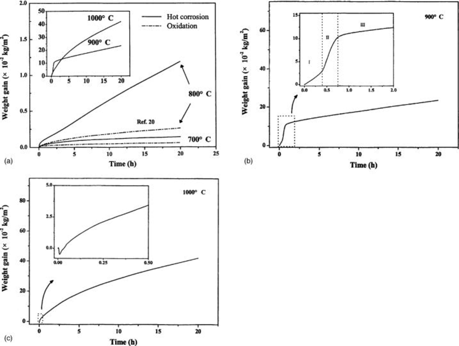
Figure 1. (a) Measured weight gains as a function of time during the exposure of  -coated
  to air at 700-1000°C. (−) The oxidation data of
  at 700 and 800°C from Ref. 20. (Inset a) Comparison of weight gains at different temperatures. (b) Hot corrosion kinetics of
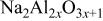
  at 900°C a showing typical tristage feature. Stage I, gestation stage; stage II, high-speed corrosion stage; and stage III, steady corrosion stage. (c) Hot corrosion kinetics of
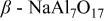
  at 1000°C showing a weight loss in the initial corrosion stage. (Inset b and c) Enlargement of the boxed areas with dot line.
At 700°C, the hot corrosion rate was low and obeyed a parabolic rate law. However, at 800°C the hot corrosion kinetics was generally linear. At 900°C where  was present in fused form, the hot corrosion kinetics showed a typical tri-stage feature for hot corrosion by fused salts, as shown in Fig. 1b. In stage I, the so-called gestation period, the weight gain increased at a relatively slow rate (7.20 mg cm−2 h−1). After stage I, the hot corrosion came into a high-speed corrosion period as marked by stage II in which the weight gain increased at a high-speed rate (22.3 mg cm−2 h−1). Due to the formation of oxides on the surface during the high-speed corrosion period, the hot corrosion rate remarkably slowed and came into stage III, i.e., the steady-state hot corrosion stage in which the hot corrosion rate was low (0.60 mg cm−2 h−1). The low weight gain rate in the gestation period (stage I) is probably due to formation of a thin oxide layer as the sample was coated with
  on the hot plate kept at 200°C.
  cannot contact
  until the thin layer of oxide formed during the coating of
  is dissolved by it. Once
  directly contacts
  it results in a high-speed hot corrosion featured by the large weight gain rate. The flux of oxygen through the sodium sulfate melt in either the gestation stage, high-speed corrosion period, or the steady-state corrosion stage cannot account for such high weight gain rates. According to Fick's first law and the approximation of Luthra,17 the flux of oxygen can be estimated by

where J is the flux of oxygen, D is diffusivity of oxygen in a sodium sulfate melt,  is the concentration of oxygen at the melt/gas interface,
  is the concentration of oxygen at the melt/carbide interface, and x is the melt thickness. D can be taken as a typical liquid diffusivity
  cm2 s−1).21 The solubility of oxygen in
  melt at 900°C is
  mol cm−3 atm−1.22 According to Henry's law,
  is estimated to be
  mol cm−3.
  is small relative to
  and can be ignored. Finally, x is calculated from the cross section to be about 14 μm. Substituting these values into Eq. 1 gives an oxygen uptake of 0.16 mg cm−2 h−1 oxygen. At higher temperature of 1000°C, no gestation period was observed. It started from a high-speed corrosion period and lasted for about 3 h, followed by a parabolic steady-state hot corrosion as shown in Fig. 1c. A weight loss in the initial stage occurred, which is similar to the interaction of TiC powders with
  in 1:1 molar ratio in flowing oxygen at 1200 K reported by Mobin and Malik.23 The initial weight loss was presumably due to the reduction of the salt to
  and/or
  and subsequent explusion of
  and
and  gases.
During exposure of sodium sulfate to air at high temperatures, especially above the melting point of  (884°C), it evaporates molecularly;24 consequently, weight loss results. So the effect of the evaporation of sodium sulfate on the hot corrosion kinetics should be taken into account. Uhlig and co-workers24 studied vaporization kinetics of
  from 900 to 1200°C in 150 Torr
  They reported that the kinetics was linear in all cases and that the rate constants at 900 and 1000°C were
  and
and  mg cm−2 h−1, respectively. As the weight gains after 20 h hot corrosion at 900 and 1000°C are in the range of tens of micrograms, the weight loss resulting from evaporation of sodium sulfate can be neglected with respect to the low evaporation kinetics of
Analogous to the hot corrosion kinetics at 800°C, the steady-stage hot corrosion kinetics at 900°C is also linear, whereas at 1000°C the steady-stage hot corrosion kinetics obeys typical parabolic rate law. The change in kinetics from linear at lower temperatures (800 and 900°C) to parabolic at higher temperature (1000°C) is discussed in detail in the following sections.
Phase identification by XRD and Raman spectroscopy.—
Phases in the specimens are the remains after hot corrosion, which can provide important information on what happened during the hot corrosion. So phase identification was carried out after obtaining the hot corrosion kinetics. The phases identified by XRD diffraction are summarized in Table I.
Table I.
| Phases identified by XRD in the specimens hot corroded in air at 700-1000°C for 20 h.a | ||||
|---|---|---|---|---|
| Phases | Relative intensities at different temperatures | |||
| 700°C | 800°C | 900°C | 1000°C | |
 | vs | vs | ⋯ | ⋯ |
 (anatase) (anatase) | vw | ⋯ | ⋯ | ⋯ |
 | w | vs | s | w |
 | ⋯ | s | vs | vs |
 | ⋯ | m | s | vs |
 | ⋯ | w | w | vw |
  | ⋯ | w | ⋯ | ⋯ |
 | ⋯ | vw | w | w |
 | ⋯ | ⋯ | w | m |
a   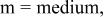  and and 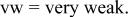
| ||||
For the sample hot corroded at 700°C, the dominant phase was  with two modifications of
  (anatase and rutile), which is similar to the oxidation in air.20 For the sample hot corroded at 800°C, the intensity of the diffractions from
  (rutile) was greater than that of
 was also detected. In addition to these two oxides, Na-containing titanium dioxide and alumina including

 and
and  were identified, which indicates that interaction of
  with
with  occurred.25 At lower temperatures of 700 and 800°C,
  substrate was detected by XRD. However at 900 and 1000°C, the substrate was not detected by XRD. At 900 and 1000°C, a species containing more Na, i.e.,
  was detected, and its intensity increased with temperature. In the temperature range 800-1000°C, the intensity of the diffractions from
  (rutile) decreased with temperature while those for Na-containing species of
  and
and  increased. It should be noted that in the samples hot corroded at 900 and 1000°C,
  substrate was not detected, suggesting that only the outer scales were detected by XRD.
Raman spectroscopy was also used to tail the changes in phase and structure evolution of oxides formed on the surface of  during hot corrosion by
  with temperature. At 700°C, characteristic Raman bands for
  (rutile) and especially that centered at 146.7 cm−1 for
  (anatase) are obviously observed. As temperature increased to above 800°C, the Raman bands showed similarity, suggesting that the oxides formed on the surface of
  during hot corrosion by
  has similar crystal structure.
Morphology observations by SEM.—
The typical surface morphologies of  -coated
  hot corroded in air at 700-1000°C for 20 h showed distinctly different characteristics. At 700°C, the surface of the sample was smooth and its microstructure was also relatively smooth. For the sample hot corroded at 800°C, the surface became rough with numerous nodules, as shown in Fig. 2a. A high-magnification micrograph of the nodules indicates that they consist of coin-like grains such as those shown in Fig. 2b. Elemental composition analysis by EDS indicates that the coin-like grains contain about 2.5 atom % Na, which is inconsistent with the XRD result in which Na-containing species are identified (Table I). As temperature increased to 900°C, nodules consisting of columnar grains are obvious. Micropores and microcracks are also observed on the nodules. Figure 2c shows the surface morphology of the specimen hot corroded at 900°C for 20 h. The micropores and microcracks are regarded as the evolution of gas phase during hot corrosion. Mobin and Malik23 studied the high-temperature interaction of titanium carbide (TiC) powders with
  in flowing air at 1200 K. They found that high-temperature interaction of titanium carbide powders with
  initially resulted in rapid weight losses followed by rapid weight gains. The weight losses are due to the evolution of gaseous phases
  during the decomposition of carbide in the presence of
  The weight gains are attributed to the formation of sodium metal oxide and metal sulfide by the mutual interaction of metal oxide,
  and
and  In the present work,
  contains a large amount of carbon whose oxidation would result in gaseous CO and/or
  these reactions are thermodynamically favorable26


The expulsion of gaseous phases through melt  left micropores and microcacks on the surface. At 1000°C, the morphology of the surface of the sample became smooth again and the grains of the oxides grew bigger (Fig. 2d). Microcracks are also observed on the surface. Elemental composition analysis of the outer grains by EDS demonstrates that the sodium content increases to 6-9 atom % Na depending on different regions.
Figure 2. (a) Surface morphology of  -coated
  hot corroded at 800°C showing that the surface after hot corrosion is not level with nodules. (b) High-magnification micrograph of (a) indicating the nodules consist of coin-like grains. (c) Surface morphology of
  -coated
  hot corroded at 900°C, indicating microspores and microcracks exist on the surface. (d) Surface morphology of
  -coated
  hot corroded at 1000°C showing that the grains of the oxides grow bigger. Microcracks also exist on the surface.
Microstructure of the hot corrosion scales.—
Information obtained from the surfaces of the samples is important to understand the hot corrosion behavior of  however, it is insufficient. The microstructure information and especially the elemental distribution from cross section is more important than that obtained from the surface. So, the cross-sectional microstructures of the samples after hot corrosion were also carefully investigated by SEM/EDS.
Because the hot corrosion at 700°C is slight; the scale is rather thin, which is in agreement with the hot corrosion kinetics (Fig. 1a). The hot corrosion rate is similar to that of oxidation in air,24 so hot corrosion at 700°C is not described in detail here.
For the sample hot corroded at 800°C, the corrosion scale is relatively thin. For those hot corroded at higher temperatures of 900 and 1000°C where fused  was present, the thickness of the scales increase markedly, revealing that
  suffered severe attack by
  at high temperatures, which agrees with the high corrosion rates at those temperatures (Fig. 1a). Figure 3a shows the secondary electron image of the cross section of
  -coated
  hot corroded at 800°C for 20 h. At 900°C, the scale consists of a porous thin outer layer, which is consistent with the surface morphology, and a relatively dense thick inner layer. In the middle of the thick inner layer, an Al-rich area is observed. At 1000°C, an obvious gap is observed between the thin outer layer and the thick inner layer in the scale of the sample hot corroded. The gap is regarded as the place where soluble salts are present during the hot corrosion. Immediately behind the gap, an Al-rich area is present. Figures 3b and c present backscattered electron images of the specimens hot corroded at 900 and 1000°C, respectively.
Figure 3. (a) Secondary electron image of the cross section of  -coated
  hot corroded at 800°C for 20 h. (b) Backscattered electron images of the specimens hot corroded at 900°C. (c) Backscattered electron images of the specimens hot corroded at 1000°C. Arrows in white indicate the
  substrate/
 interface.
We have known that at 800°C, the steady-stage hot corrosion kinetics is linear, which suggests that the rate-limiting step is not diffusion. Maps of element distribution and line scan along the white line as shown in Fig. 3a-c are in good agreement. For the sake of brevity, only the line scan results are shown in Fig. 4. From those results, it is clear that an obvious sulfur-rich area is present at the  substrate/scale interface. For the specimens hot corroded at 900 and 1000°C, sulfur-rich areas are also observed at the
  substrate/scale interfaces. The presence of sulfur-rich bands at the substrate/scale interfaces demonstrates that chemical reaction of
  with
with  occurred during hot corrosion. Another feature of the sulfur-rich bands is that the sulfur-containing species can be soluble in water because clear traces of dissolution are obvious at the
  substrate/scale interfaces where gouges are present. Figure 5 shows the high-magnification micrograph at the
  substrate/scale interface as indicated by the white arrow in Fig. 3c. Dot analysis results of elemental composition at the interfaces are summarized in Table II. It is seen from Table II that the sulfur content decreases with increasing temperature. The higher sulfur content at the
  substrate/scale interface of the sample hot corroded at 800°C suggests that the hot corrosion was still in an active stage.

Figure 4. Line scan results along the white lines as shown in Fig. 3a-c. It is obvious that sulfur-rich bands are present at the  substrate/
 interface.

Figure 5. Secondary electron image of the  substrate/
 interface as indicated by white arrow in Fig. 3c, showing the presence of a gauge in which soluble species are formed.
Table II.
| Results of quantitative element analysis by EDS at the substrate/scale interfaces of the specimens hot corroded in air at 800-1000°C for 20 h. | ||||||
|---|---|---|---|---|---|---|
| Temperatures (°C) | Elements and atom % | |||||
| Ti | Al | S | Na | C | O | |
| 800 | 11.71 | 0.91 | 6.63 | ⋯ | 64.10 | 16.66 |
| 900 | 11.07 | 2.51 | 0.56 | 0.16 | 41.29 | 44.41 |
| 1000 | 5.59 | 8.62 | 0.31 | 0.77 | 39.90 | 44.80 |
Hot corrosion mechanism of  coated with .—


In the previous works on the oxidation of  in air, an inner continuous
  layer was formed at high temperatures and the amount of
  increased with temperature, enabling excellent oxidation resistance.3 Whereas, for the hot corrosion of the same material at all temperatures investigated in the present study, no continuous
  layers were observed even at the highest temperature of 1000°C. The difference in the latter case from the former is that there is a layer of
  coating on
  during exposure to hot air. Therefore, the effect of
  should be discussed.
Until now several hot corrosion mechanisms including sulfidation,27 acid-basic dissolution,28 and electrochemistry29 have been proposed. No matter what the mechanisms are, the character of  needs to be understood first.
  is an electrolyte which follows the following equilibrium6

Any reaction that is favorable for the reaction moving to the right would result in the dissociation of 
Because fused  is an ionic conductor, the hot corrosion mechanism should generally be electrochemistry. In other words, hot corrosion itself is an electrochemical process that includes anodic oxidation, cathodic reduction, and ion diffusion. In the hot corrosion of
  anodic oxidation mainly consists of the anodic dissolution of Ti and Al
Accompanying the anodic dissolution, strong reductivity results in the reduction of 
 Some
Some  anions are formed and combine with cations of Ti and Al to form oxides, and the others increase the basicity in the fused
 anions and their reduction product
  could migrate inward through nonprotective scale, e.g., in the scale/ceramic interface where the reductivity is high enough for the formation of sulfides. In this study, sulfur-rich bands are present in the scale/ceramic interfaces (Fig. 3 and 4), implying that the reductivity is much higher there.
The cathodic reaction process consists of the reduction of  anions and oxygen. The weight gain during hot corrosion comes from the oxygen in air. In fused sulfate there is an equilibrium

Oxygen in atmosphere can be dissolved in melt according to the following equation
Apart from oxygen in molecular form in the melt, its main presence form is  Because the solubility of oxygen in fused salt is small21 and its diffusion rate slow,22 diffusion of molecular oxygen in the fused salt to the ceramic surface cannot account for such high weight gain rate. The concentration of
  ions according to Eq. 8 increases with increasing temperature, and then the concentration of
  increases, which consequently results in the increase in the corrosion rate of alloys.
  migrated to the surface of the scale
  and was reduced, which contributed to the formation of new oxides. Because fused salt is a strong electrolyte, the diffusion of
  ion migrating to the surface of the scale is sufficient to support such high weight gain due to corrosion.
As  anions were reduced, basicity increased in the fused salt and the basic dissolution of oxides, especially
  occurred30
31
occurred30
31
After basic dissolution of  occurs, the formed
  ions migrate to the place where the basicity is low. In the place where
  can stably exist, it precipitated again. In the specimens hot corroded at 900°C, the precipitated
  existed in the middle of the scale; while in the sample hot corroded at 1000°C it was present in the nearly outer layer. The fact that the Al-rich layer moved outward at 1000°C implies that the basicity near the ceramic/scale interface increases with increasing temperature. Due to the dissolution of
  and reprecipitation, the compactness of scales decreased, which is favorable for the diffusion of ions.
Because the scale formed at 900°C is relatively thin and the compactness is low, the kinetics in steady stage is linear. It is thus reasonable to conclude that the rate-limiting step at this temperature is the electrochemical reaction between the fused salt and  rather than the diffusion of ions. At 1000°C, the precipitated
  layer is dense, and the kinetics in steady stage is parabolic, which suggests that the rate-limiting step at this temperature is the diffusion of ions.
At low temperature of 800°C, although this temperature is below the melting point of  the morphology of the hot-corroded specimen is rough, implying that fluxing took place during hot corrosion. Given the fact that the kinetics in steady-stage corrosion is linear, it is reasonable to conclude that the rate-limiting step is the electrochemical reaction of
  substrate with the salt.
Conclusion
Hot corrosion of  -coated
  in air at 700-1000°C was studied. No protective scales were observed, which accounts for the severe hot corrosion of
  by fused
  at 900 and 1000°C. Below the melting point of
  the hot corrosion attack was slight, whereas above the melting point of
 suffered severe hot corrosion attack by fused sodium sulfate. At 900°C and even at low temperature of 800°C, the hot corrosion kinetics was linear, which suggests that the rate-limiting step was the reaction at the substrate/scale interface. At 1000°C, the parabolic kinetics indicates that diffusion of corrosion medium through the formed scale controls the hot corrosion rate.
Acknowledgments
This work was financially supported by the National Outstanding Young Scientist Foundation for Y. C. Zhou under grant no. 59925208, the National Science Foundation of China (NSFC) under grant no. 50072034 and 50232040, '863' program, Chinese Academy of Sciences and the IMR Innovative Research Foundation.
Dr. Yanchun Zhou assisted in meeting the publication costs of this article.