

Abstract
The brain capitalizes on the complexity of both its biochemistry for neurons to encode diverse pieces of information with various neurotransmitters and its morphology at multiple scales to route different pathways for neural interconnectivity. Conducting polymer dendrites can show similar features by differentiating between cations and anions thanks to their charge accumulation profile and the asymmetry in their dendriticity that allows projecting spike signals differently. Here, we exploit such mimicry for in materio classification of bursting activity and investigate, in phosphate buffered saline, the capability of such object to sense bursts of voltage pulses of 100 mV amplitude, emitted by a local gate in the vicinity of the dendrite. The dendrite integrates the different activities with a fading memory time window that is characteristic of both the polarity of the spikes and the temporality of the burst. By this first demonstration, the 'material-object' definitely shows great potential to be a node halfway between the two realms of brain and electronic communication.
Export citation and abstract BibTeX RIS

Original content from this work may be used under the terms of the Creative Commons Attribution 4.0 licence. Any further distribution of this work must maintain attribution to the author(s) and the title of the work, journal citation and DOI.
1. Introduction
In order to propose better tools that help understanding complex environments, information technologies are in perpetual evolution, from sensing hardware that generates data to classifying software that sorts information. Between the sensing nodes and the algorithm architectures, computers are re-engineered to process information in the most efficient way while consuming the least energy and lessening the amount of data needed to train for pattern recognition. Instead of building computers with faster transistors, the neuromorphic paradigm proposes to connect the different building blocks of a system with a high level of parallelism, drawing inspiration from neural networks. It is specifically the nodal structure and the high degree of parallelism between memory units and processing units that allows building integrated circuits with outstanding processing performances and reasonable power consumption [1]. As they aim at offering generic solutions for pattern recognition tasks, neuromorphic systems do not generate data themselves, but process them very efficiently. Thus, the von Neumann framework drives manufacturers to build computers regardless of sensing technologies and machine learning architectures. For instance, neuromorphic chips such as the Loihi 2 are intrinsically limited by their number of GPIO (general purpose input/output). This prevents the input of high dimensional data directly in parallel, regardless of the sophistication of the data processing steps: the advantages of high parallelism are lost at the data generation stage. To match any specific sensing challenge, subparts and elementary functions of such systems are designed as generically as possible to make them universally interchangeable. However, the complexity of the classification task can sometimes be hardly assessable beforehand because of the difficulty to physically define classes of information with a model. If the complexity of that challenge is underestimated, too few sensors/slow computers/generic models will not provide sufficient information descriptors for classification. Conversely, overestimating complexity leads to oversizing the sensing array. That, combined with too flexible machine learning algorithms, can rapidly cause overfitting, unless sufficiently big training datasets can practically be provided. Sensing applications involving edge-computing use neuromorphic blocks as a bio-inspired way to locally preprocess the information on each pixel of a sensitive array. This is even more efficient when the information is spatially high dimensional and necessarily requires to pattern many inputs on a substrate [2–7]. In addition, as large enough datasets are not always accessible to train systems for reliable classification, there is a great need to find sensing figures of merit that provide guidance on sizing sensing tools according to classification tasks [8], and on creating hardware which sophistication evolves online according to the complexity of such tasks. This is particularly striking in the case of neurosensing: the high complexity of processing spatiotemporal data lies in the too few sequences that can practically be recorded and stored. Online processing would require the extension of parallelism from the sensing stage all the way to the computing units.
Inspired by brain plasticity [9], conducting polymer dendrites are a class of neuromorphic wetware that shows a lot of promise for such adaptation, as their structural complexity can scale up in operando upon voltage activation to match required interconnectivity levels [10–13]. Inherent morphogenesis upon exposure to voltage spikes is specific to the waveform parametrizing that governs interconnection asymmetry, density and fractality. In that way, it becomes possible to route pathways using a selection rule based on the occurrence of voltage spikes in order to hardconnect electrical nodes [14]. Moreover, these dendrites behave as organic electrochemical transistors (OECTs) at the single interconnect level [15, 16], and show synaptic plasticity similarly to their thin-film equivalent [15, 17, 18]. Their volatile memory, which temporal decay lasts over seconds, is a function of their complex morphology, engraving all of the voltage experience that took place during their genesis [15]. At large scale, global- and self-gating of integrated dendrites allows storing multiple states on different branches, so reservoir computing is enabled to project a signal input on multiple dendritic outputs to a higher dimensional plane that improves data separability and makes it possible to recognize sine wave voltage patterns [19]. Applications toward ex-vivo biosignal classification demonstrate the applicability of such unconventional electronics [20]. As thin-film OECTs are able to sense neural activity [21], and hold potential for in operando sensing adaptation [22], integrating both aspects in conducting polymer dendrites is an exciting prospect, as one could take advantage of the morphological complexity of these objects to bring computational functions closer to the sensing layer. In the perspective of neurosensing, we study the ability of conducting polymer dendrites to operate in phosphate buffered saline (PBS), and how their asymmetric morphology allows extracting various information features out of bursts of 100 mV spikes, generated in the vicinity of the dendrites.
2. Growth and electrical characterization of conducting polymer dendrites
2.1. Experimental setup
Former studies highlight the relevance of tuning the voltage waveform for AC-electropolymerization of 3,4-ethylenedioxythiophene (EDOT) monomers into electropolymerized poly(3,4-ethylenedioxythiophene) (PEDOT), to enable a given morphology according to the gap between two electrodes acting as anode and cathode during the reaction [11, 14]. In the present study, growth was performed in a 40 μL water drop containing 1 mM of poly(sodium-4-styrene sulfonate) (NaPSS) as electrolyte, 10 mM of EDOT and 10 mM of 1,4-benzoquinone (BQ) to counterbalance at the cathode both the rates of proton and electron flows during the anodic growth of dendritic material (all chemicals purchased from Sigma Aldrich and used in air as received). The electrical setup is displayed in figure 1(a) and was performed with a ground-centered square wave (duty cycle = 50%, no voltage offset). Both 25 μm diameter Au wires (purchased from GoodFellow, Cambridge, UK), 240 μm apart, served as anode and cathode intermittently, so that growth would occur on both wires simultaneously. It is worth noticing that neither of them is potentiostated and that the setup does not require any electrochemical reference electrode during the experiment: gold wires are directly polarized with a voltage supply (50 MS s−1 dual-channel arbitrary waveform generator from Tabor Electronics), so the gap could be further downscaled at will without placing a third electrode closer to a working electrode than to a counter one. Subsequently, 40 μL of a two-time concentrated phosphate buffered saline (2× PBS) was gently introduced in the electrolyte to assess the electrical properties of the dendrites (with an Agilent B1500A Semiconductor Device Analyzer for DC characterizations and a Solartron Analytical Ametek impedance analyzer for the impedance spectroscopy). The setups are depicted in figures 1(b) and (c), where the gate electrode is a 25 μm diameter Ag wire also purchased from GoodFellow. Electrochemical impedance spectroscopy (EIS) was performed under a DC voltage of 100 mV in absolute value and VAC = 10 mVRMS, low enough to avoid non-linear distortions.
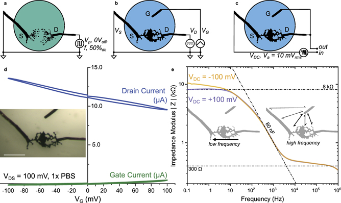
Figure 1. Dendrite electrical characterization. (a) Experimental setup for electrochemical formation of PEDOT dendrites in a low-ionic content aqueous electrolyte composed of NaPSS and benzoquinone. (b) Experimental setup for the DC electrical characterization of the dendrite for the transfer characteristic. (c) Experimental setup for the AC electrochemical impedance spectroscopy of the diode-connected dendritic transistor. (d) Transfer characteristics of a dendritic-channel transistor in PBS, also containing BQ (5 mM), NaPSS (0.5 mM), EDOT (5 mM) and the products of the electropolymerization reaction, using a local silver wire as a gate (inset: morphology used for the electrical characterization scale bar: 200 μm). (e) Impedance spectroscopy of the conducting polymer dendrite under two different VDC voltage biases promoting either the electrochemical dedoping (orange) or the doping (purple) of the dendrite (inset: schematic of the different conduction modes responsible for the voltage variance and invariance at different frequencies).
Download figure:
Standard image High-resolution image2.2. Steady characterization
As the dilution leads to a 1× PBS solution with the presence of electroactive solutes resulting from the electropolymerization, electrical operation and characterization were performed with a maximum DC voltage bias of 200 mV in absolute value. That choice was made in order to avoid triggering electropolymerization, which would further modify the morphology and ultimately the electrical properties of the dendrite while performing the characterization. The use of PBS is not inconsequential: as it is isotonic and non-toxic for most cells, such aqueous electrolyte has been chosen as a model to demonstrate suitability in biological environments. Within such a voltage window, transfer characteristics of a short-circuited dendritic interconnect were recorded with both positive and negative gate voltage (VG) biases (see figure 1(d)): as a p-type semiconductor, the reversible increase of drain current (iD) with VG < 0 V, and its decrease with VG > 0 V, is caused the modulation of the concentration of cationic charge carriers at the dendrite, which in turn impacts the charge carrier density in the semiconductor to respect local electroneutrality. Also, we observed that the conductance of the dendrite is rather stable during the measurement with no pronounced hysteresis between traces and retraces at ±20 mV s−1 (see figure 1(d)). The drain current modulation shows a linear relationship with gate voltage, with a transconductance of 20 μS for |VG| < 100 mV. As the transconductance values for the two polarizations are comparatively similar, one can assume that the same physical process dominates in both cases, presumably the doping/dedoping of the material due to the modulation of cation concentration [23, 24]. The concomitant counter-contribution of the anions is also to be taken into account, but their surface effect on the dendrite periphery is most likely less important regarding the dendrite conductance than the one of cations that charge and discharge the bulk of the material. The ensuing drain current (iD) modulation of ±2 μA at |VG| = 100 mV (with a gate current iG of about 400 nA) indicates a minor contribution of the gate Faradaic current to the drain current modulation (<20%). In accumulation mode (VG < 0 V), the Faradaic current is completely absent, which suggests a genuine transistor effect. The origin of the minor Faradaic contribution observed only under positive gate voltage bias is attributed to the silver gate sensitivity to oxidation in the presence of electroactive species (see supplementary figure S1(a)). Although gold does not show such sensitivity to benzoquinone, steady transfer characteristic tests demonstrate very moderate transistor effect with such micrometric gate (Cicoira and co-workers have shown that in the case of a gate electrode area that is comparable to the size of the channel, gate electroactivity matters for an effective operability in an electrochemical transistor) [25].
2.3. Impedance spectroscopy
The presence of 1× PBS as supporting electrolyte strongly increases the ionic strength of the electrolyte compared to the 1 mM NaPSS initially constituting the medium used for dendritic growth. As such, the dendritic electrochemical transistor can be characterized in a diode-connected configuration (drain shorted on gate), to observe two different regimes at low and high frequency, embedding different ion-specific states [26]. In this particular case and because of the addition of PBS, the dendrite becomes less conductive than the electrolyte. Consequently, there is no need to place a resistive load on the channel path to monitor the lower impedance electrolyte response at high frequency, and the dendrite doping state response at low frequency, displayed in figure 1(e). This behavior is not observed before adding PBS (see supplementary figure S1(a) for comparison) and shows to be typical of high ionic strength electrolytes such as 1× PBS. This implies that conducting polymer dendrites should not behave as resistive wires in physiological solutions, and their capacitive response shall greatly influence their dynamics at such length and concentration scales. The increase in ionic strength of the electrolyte brings to light two different behaviors, mostly due to the gate-voltage dependent dendrite conductance (figure 1(e)). As VDC = +100 mV, the gate wire has the lowest polarity in the electrochemical environment, causing the dendrite to behave as a conductive wire with a low frequency plateau up to 10 Hz. On the other hand, if VDC = −100 mV, the source electrode shows the lowest polarity and pulls down the dendrite potential, which dedopes the dendrite within the vicinity of the source electrode. As a consequence, it appears that the dendrite response is not yet steady at low frequency (down to 0.1 Hz). From this behavior, two particular dynamics for the dendrite charge and discharge might be extrapolated, depending on the polarity of the incoming signal in regard to the dendrite polarization: in case an ionic wave promotes either the doping or dedoping of the dendrite, cationic or anionic waves of the same amplitude shall promote very different dynamics in the time domain, with incoming cation waves being much slower to charge the dendrite than anion ones. Considering the frequency range for the impedance transience observed at VDC = −100 mV, it is supposed that the ten-second scale dynamics responsible for such effect is not attributed to the anion charge accumulation on the surface, but rather to the cation diffusion within the bulk of the material that may be limited by two factors. The first one is the intermolecular structure of the electropolymerized PEDOT, for which the low conductance reveals PEDOT pure domains that are hydrophobic and hard to access for cations. The second one is the morphology of the dendrites, where 'dead-end' loose branches do not contribute to the channel conduction path but to the device capacitance. This partly explains why almost no hysteresis is observed in the transfer characteristics, while slow dynamics is suggested for accumulation mode stresses in the impedance characterization. Such behavior has been assessed in the time domain with square voltage patterns.
3. Response of conducting polymer dendrites to bursts of voltage spikes
Bursts of action potentials play a major role in the transmission of information within biological neural networks [27, 28]. As a preponderant feature of neural signaling, spikes are detected by thresholding the electrophysiological recordings on microelectrode arrays [29, 30]. Various methods exist to adapt this threshold [31–35], which is however always specific to each electrode as a statistical parameter taking into account past activity. In the following demonstration, we show that using dendrites to sense spike signals allows classifying spike pattern activity with such threshold, sensing output features that are generic and not relative to the sensor statistics. Different configurations have been evaluated based on the polarization of the two dendritic terminals and the unipolarity of the spikes generated at the gate. These positive or negative unipolar voltage pulses always have a 100 mV amplitude with respect to a specific resting potential, relative to the polarization of the dendrite. Bursts of such periodic spikes are generated by interrupting signal transmission on the local gate with a mechanical switch (figures 2(a)–(d)). Based on the polarity of the dendrite terminals, we observed that both terminals on a single dendrite collect different pieces of information in their output current, which enables retrieving both the polarity of the spikes and the temporality of a burst (figures 2(e)–(h)). The parameters of the input signal were inspired by the activity of neurons in the brain. However, one has to keep in mind that this laboratory model, chosen for the sake of the experiment, is far from being biologically relevant, given the amplitude or the polarity of the spikes fired by the waveform generator. Let us also remark that the setup used in that section of the article differs from the EIS one. The duration that the dendrite has to charge and discharge is in both cases very different, and what is put forward in the following of the text is the ability of the material to perform short term plasticity: because the charge/discharge time constants of the dendrite are dissimilar, the repeated projection of an input signal creates an imbalance which gives birth to a short term memory effect.

Figure 2. Source and drain current outputs upon gate stimulations of burst sequences of voltage spikes. (a) Experimental protocol illustrating the setup used with a DC bias for source and drain current readouts, and spike voltage generated from the local gate that is manually modulated as burst packets with a mechanical switch. (b) Voltage spikes are periodically sequenced at 200 Hz and size 100 mV vs GND and 0.5 ms (green highlights the integration period for the source and drain currents measurement). (c) Source and drain current sampling is synchronized with the gate input at a rate of one sample per 12 spikes. (d) Information is modulated as short- and long-lasting bursts of spikes with the push button. (e)–(h) Source and drain current dynamical responses recorded during four cases, in which short-spiking events increase the local gate potential (case 1(e) and case 3(g)), or decrease it (case 2(f) and case 4(h)). These tests have been performed with either a positive drain–source voltage bias (case 1(e) and case 4(h)) or a negative one (case 2(f) and case 3(g)). In the (e)–(g) schematics, on the left are depicted steady ionic charge accumulations assuming cations (in red) accumulate in the bulk of the dendrite and anions (in blue) accumulate at the surface of the dendrite. On the right, the red and blue curves indicate the source (iS) and drain (iD) current values, centered on the initial current state of the dendrite. The gray bars depict the moments where the push button is in 'bursting state'. Scale bars at the bottom of the picture hold for the four cases.
Download figure:
Standard image High-resolution imageAs seen previously, conducting polymer dendrites charge and discharge with different kinetics based on the fact that cations and anions accumulate and diffuse differently in or on the dendritic material. As both kinetics differ, as shown by impedance spectroscopy, so does the temporal dynamics of the projection of spikes on the dendrite, based on the polarity of the spike train and its ability to promote either the electrostatic dedoping of the dendrite or the slow diffusion of accumulated cations within its bulk.
Experimentally, we observed that the dendrite responds faster to bursts of positive spikes (cases 1 and 3 in figures 2(e) and (g)) than to bursts of negative spikes (cases 2 and 4 in figures 2(f) and (h)). Independently from the duration of these bursts, after the initial five-second resting period, the modulation of both drain and source output currents is systematically reaching its maximum when spikes are positive (cases 1 and 3 in figures 2(e) and (g)). In the case of negative spikes (cases 2 and 4 in figures 2(f) and (h)), a slow build-up takes place over time before reaching maximum modulation, which requires bursts to occur either with a certain duration, or at a certain rate. This basically shows that depending on local activity, the dendrite senses and projects specific pieces of information at both outputs. The temporal evolution of the output signal does not give any clear indication on the state of the dendrite but rather on the charge dynamics in the vicinity of the sensor, and whether a local voltage pulse promotes either withdrawal or accumulation of cations or anions. In addition, we also observed that the modulation of the output currents depends on the direction of the electric field applied across the dendrite, in relation with the structural asymmetry resulting from the dendritic morphology. When the dedoped front is located within the vicinity of the source electrode (figures 2(e) and (h)—space-charge of dedoping cations is illustrated as the red-shaded region in the bulk of the dendrite), the current modulation upon burst stimulation is more important than when the dedoped front is located within the vicinity of the drain electrode (figures 2(f) and (g)). Though the conduction path does not depend on the polarity of the wires (no diode effect has been observed on the output characteristics of the conducting polymer dendrite), the different dendritic morphologies at the source and the drain induce different capacitance and time constants depending on where the bias promotes larger ion accumulation. As we observe larger current modulations when the branches originating from the source are dedoped (figures 2(e) and (h)—space-charge of anions is represented as a blue-shaded line on the dendrite surface) compared to when the ones growing from the drain are dedoped, we can conclude that the drain region in the conducting polymer has a larger specific capacitance than the source one, presumably because of a substantially more branchy structure (if we observe the image inset in figure 1(d) and the setup in figure 2(a), we can qualitatively be positive regarding this assumption in light of the information provided by the 2D image). The four cases depicted in 2 actually correspond to the pulses doping/dedoping one side of the dendrite. Together with supporting informations figure S2, which shows that inverting source and drain does not impact the impedimetric signature of the dendrite, it supports the claim that the asymmetry of the response is a consequence of the morphology of the dendrite, and not only of the biasing conditions. Considering the fact that the morphological asymmetry can entirely be tuned during dendritic growth by playing with the voltage stimulation [14, 36], modifying the dendrite asymmetry can be a mean to extract different pieces of information on both source and drain currents from the same sensing object, with various sensitivities according to the morphological structure of the conducting polymer dendrite.
Using both dendrite terminals individually allows recognizing the activity of the vicinal firing gate, as both the polarity of the spikes that elicited a response in the material as well as the temporality of these successive events can be retrieved. Indeed, figures 3(a)–(c) shows that the source/drain voltage bias obviously leads to different source and drain currents, but that such currents imprint different patterns according to the polarity of the dendrite and also of the pulse events. Moreover, in both cases, if the system is at rest and no burst is fired (empty circles, the dashed line shows iS = −iD), drain currents strictly equal the opposite of the source currents (charge carriers are evacuated in a symmetrical way from both dendritic terminals).

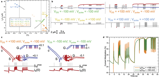
Figure 3. Source and drain current analysis and feature extraction. (a)–(c) Correlation between source and drain currents recorded at both dendrite terminals during different bursting sequences of the local silver gate. Same currents as displayed in figures 2(e)–(h), same color code for the four different polarization cases with VDS and Vpulse. (d)–(f) Correlation between the ratio of source and drain currents (d) and their sum (e), displaying a monotonic relationship between the gate current and the dendrite current asymmetry at a given VDS (f). The indexing for the different signal sequences starts at zero for the first resting period and increments in absolute value with chronological order. Burst sequences are positives so first, second and third sequences of burst are indexed '1', '2' and '3', and resting sequences are negative, so second, third and fourth sequences of rest are indexed '−1', '−2' and '−3'.
Download figure:
Standard image High-resolution imageUpon application of voltage bursts, classification rules depending on the polarity of the spikes can also be found. From figure 3, it clearly stands out that when the polarization of the burst is similar to that of the dendrite, the absolute value of the source current is higher than the absolute value of the drain current (VDS = Vpulse ⇒ |iS| > |iD|). For example, when VDS = Vpulse = −100 mV a great majority of the recorded points are standing below the dashed line (figure 3(a), green solid circles). However, when the polarity of the dendrite is the opposite of the polarity of the spikes applied at the gate electrode, then the absolute value of the drain current appears to be superior to that of the source current (VDS = −Vpulse ⇒ |iD| > |iS|). This is better represented in figure 3(d) which shows iS/iD, as the green and blue dots (VDS = Vpulse) stand above the unit line (|iS/iD| = 1), whereas the yellow and orange circles (VDS = −Vpulse) do not cross that line.
Such asymmetric behavior relies on both the potential asymmetry between the source and the drain versus the pulse polarity and the asymmetry of the dendritic morphology: when VDS = Vpulse, the highest difference of potential in the system lies between the source and the gate (|VDS| = 100 mV, |VGS| = 100 mV, |VGD| = 0 V). As such, the electrochemical current would preferentially flow between the source electrode and the gate, having the largest voltage bias. Reciprocally when the pulses and the bias of the dendrite are of opposite polarities, the maximum voltage drop within the system takes place between the drain and the gate, as |VGS| = 100 mV and |VGD| = 200 mV, which drives the gate current to be evacuated on the drain terminal of the dendrite. In addition, the morphological asymmetry of the dendrites yields different capacitances for both drain and source sides of the dendrite. As a result, there is no symmetry between the top-right and bottom-left quadrants in figure 3(a), which shows that the source–drain biasing that induces a different charge accumulation along the dendrite can collect two different imprints of a same temporal voltage pattern emitted from the vicinal gate.
Despite the distinctive behaviors of the source and drain currents with respect to gate pulses and dendrite bias, we observed common trends between the asymmetry between the currents and the sum of both, as displayed in figures 3(d)–(f), which quantifies the relationship between gate activity (−iG = iS + iD) and current asymmetry iS/iD. In figure 3(f), we observe that because of the morphological asymmetry, the source/drain current ratio is not strictly proportional to the gate current and more importantly that the sensed activity for a given polarity is not equal to the opposite of the sensed activity for the opposite polarity.
From this correlation between iS + iD and iS/iD, one can observe that setting the threshold limit detection on current asymmetry can lead to a similar data separation as a threshold on gate activity (−iG = iS + iD), as the latter is monotonic with iS/iD at a fixed VDS bias. This highlights a main advantage for electrochemical transistors compared to passive electrodes as here, the threshold can be set on an adimensional relative value and not an absolute value of current and voltage, that would require calculating the statistics to estimate the threshold. By directly using the source/drain current asymmetry as a threshold limit for detecting gate activity, one does not need to repeatedly calculate the signal standard deviation.
In figures 4(a)–c, we can observe that placing a current ratio threshold limit (figure 4(a)) allows classifying the recorded activity according to the polarity of the pulses and the voltage bias of the dendrite (figure 4(b)). In the case of negative pulses, we observe that a threshold limit on the dendrite current asymmetry allows identifying most of the bursting activity. However, when the pulses are positive, data separability between bursting and resting becomes more difficult. We can nevertheless notice that when VDS = +100 mV and Vpulse = +100 mV, the threshold allows detecting the first occurring burst after a 5 s rest (figure 4(b)), and this despite the fact that looking individually at source and drain currents would not allow such temporal discrimination.
Figure 4. Current ratio thresholding and asymmetry in memory volatility. (a) Highlights on current ratio data of figure 3(f) that are above and below a user-defined threshold, specific for the four different polarization cases. (b) Figures 2(e)–(h) current versus time measurements for the four different cases, where current data corresponding to the detection of figure 4(a) are marked in blue and red (traces in gray correspond to output currents below detection thresholds, set by the same current ratio thresholds than in figure 4(a)). (c) Sequenced pulse facilitation of the source and drain currents of the dendrite in case Vpulse = −100 mV. (d) Relative current modulation for the source and drain currents of the dendrite in case Vpulse = −100 mV.
Download figure:
Standard image High-resolution image
The case of negative pulses shows a richer temporal response of the dendrite than the one of positive pulses. As discussed previously, cations are slower to charge/discharge the dendrite than anions, which allows observing sequenced pulse facilitation at the second scale (figures 2(e)–(h)). Furthermore and thanks to the morphological asymmetry of the dendrite, current amplitudes differ depending on VDS and whether it promotes ion accumulation toward the source or the drain (figure 4(c)). Moreover, this impacts directly the output current modulation as shown in figure 4(d), in which the sequenced pulse facilitation reaches more rapidly its maximum amplitude in case VDS = +100 mV, which promotes cation accumulation on the source side of the dendrite (figures 4(c) and (d)). By using both the morphological asymmetry of the conducting polymer dendrite and the cation/anion charge/discharge asymmetry in the polymer, we show that such objects can distinguish between unipolar signals of different polarities, generating in some defined cases sequenced pulse facilitation, with a different memory time-window depending on the dendriticity of the multipolar sensor, and the way we address it to read the drift current.
Before the technical limitations of the setup depicted in this study, it was not possible to induce a high level of morphological asymmetry during dendritic growth. Therefore, further work on the matter might provide more insight into the possibilities offered by such objects. This might be achievable by focusing on integrating the dendrites on a substrate, something that the authors are working on and that has already been demonstrated by other groups [13, 36]. When it comes to integration and integrated circuits, it is also only natural to mention the tremendous efforts done by Khodagholy's team to move toward ever more integrated neuroelectronics [37, 38].
4. Conclusion
Conducting polymer dendrites are objects that demonstrate genuine neuromimetism in both material morphology and electrical operability. As devices, one can take advantage of the material versatility for more sensing functionalities: they can be electrochemically grown in water, without any organic solvent. In a phosphate buffered saline solution, they can display transistor-like behavior using a micrometric silver wire as local gate electrode without preponderant Faradaic contribution in a –100 mV/+100 mV voltage bias window. Impedance spectroscopy evidenced ion-specific dynamics. Indeed, the impedance response of the diode-connected dendritic transistor in the saline shows high-pass filtering properties where the electrochemical doping modulation induces different temporal signatures, so that an anionic charge on the dendrite appears steady within 100 ms while a cationic one is still transient after tenths of seconds following a similar voltage amplitude input. Thanks to this asymmetry in the temporal dynamics of ionic charge carriers, the dendrite is able to mimic short term plasticity depending on whether ions penetrate the bulk of the material to dedope the dendrite or accumulate at the surface. Extracting features from source and drain currents allows determining the charge polarity of ionic events in the vicinity of spiking local gates, as well as the temporality of these events. With further integration improvements for these biomorphic electrochemical devices on emerging sensing platforms, conducting polymer dendrites shall contribute to solving the huge computational challenge behind neural activity pattern classification by pruning data with zero computational cost, via sensors that are neuromimetic both in the way they compute information and in their material structure that governs their electrical properties.
Acknowledgments
The authors thank the French National Nanofabrication Network RENATECH for financial support of the IEMN cleanroom. We thank also the IEMN cleanroom staff for their advice and support. This work is funded by ERC-CoG IONOS Project #773228.
Data availability statement
The data that support the findings of this study are available upon reasonable request from the authors.
Conflict of interest
The authors declare no competing interests.