
Abstract
Thermal stress is a very common phenomenon that occurs at the welded joint. Determination of the same at the joint is however difficult due to inhomogeneity of the weld joint metals and spreading of heat to the surroundings from the Heat Affected Zone (HAZ). Thermal stress induced at the welded joint changes the microstructure of grains which affects the mechanical properties of the welded material. Due to this, cracks may appear in the joint leading to failure of the weld. In the present study, three-dimensional model of two types of welded joint, i.e., Tee Joint and lap joint of two plates having dimensions 100 mm × 75 mm × 5 mm are prepared using ANSYS Workbench 2020 R2. Hex dominant meshing is chosen in order to have clear picture of the spread of temperature over the entire region. The change of Residual stress with variation of welding current and keeping welding voltage constant is also observed for weld joint made of Aluminium Alloy. In this study, conduct steady-state thermal analysis and structural analysis on an aluminium alloy 6063 to assess von Mises stress, von Mises strain, and deformation distribution induced by heating. Evaluate various welding joints to identify the most effective technique.
Export citation and abstract BibTeX RIS
1. Introduction
Welding is a joining process that is widely used in industries. High amount of heat is generated during welding which is followed by rapid cooling [1–4]. It generates residual stresses and distortion in the weld and base metal. In last few decades significant number of research have been carried out aiming at reducing residual stress and distortion [5–8]. It is very important to predict these residual stresses and distortion problems prior to the actual welding process [9–11]. It can be predicted with less effort and in an inexpensive way with the use of finite clement method [12–15]. In this chapter brief idea of thermally induced stresses and strains and basic concept of MIG welding are discussed. It also includes concise idea about different types of weld joints [16–19]. Plasma arc welding (PAW) is an arc welding process very similar to TIG welding as the arc is formed between a pointed tungsten electrode and the workpiece [20–23]. Plasma is then forced through a fine-bore copper nozzle which constricts the arc [24–27]. Temperature is near about 3000 °C to 17000 °C generated. Then, in this temperature filler metal is melted and joint the plate [28–31].
Gaidhani et al [32] performed Finite element analysis on double wire submerged arc welding. Thermal and mechanical simulation of welding joint using heat input and welding speed were given as boundary conditions to determine temperature distribution, heat flux for tee joint of stainless steel. Krishnamoorthy et al [33] accomplished transition thermal analysis of Tee joint of stainless steel 304 l plates has been evaluated to perform and used to determine temperature distribution by ANSYS software. Lee et al [34] studied three-dimensional finite element welding simulation of circumference for two steel plate three-dimensional model. It has been concluded that three-dimensional finite element model is essential to accurately simulate the circumferential welding of a steel pipe which can incorporate the three-dimensional effects. Stamenkovie et al [35] conducted finite element model analysis of residual stress in butt welding of two similar plate. So, they can perform structural and transition heat transfer analysis by given boundary condition such as cylindrical moving heat source. They analysis residual stress distribution over the plate of butt joint. Sattari-Far et al [36] performed thermo mechanical analysis to find residual stress distribution of butt joint to evaluate accuracy of finite element model. After the analysis, they compared the final data of finite element model with experimental studies. They observed the effect of residual stress due to welding groups, welding pass and also welding speeds. Jianmin et al [37] conducted the finite element analysis of submerged arc welding process using ANSYS software. They used double elliptical heat source model and taken convective heat transfer and heat flux as boundary condition to determine temperature distribution and heat flux of welding joint for structural steel plate. Vemanaboina et al [38] used uniform working cylindrical heat flux is given to welding joint of two structural steel 304 plate to perform structural and statistic thermal analysis to determine temperature distribution and stress distribution of welding joint. Srecnivas et al [39] accomplished longitudinal and transverse stress analysis of TIG welding using ANSYS software. They used moving heat flux source to study numerical method of welding to determine stress. After the analysis, they compared with the experimental data to observe the effect of steel due to change of torch speed. Jilie et al [40] implemented finite element model analysis on thermal distribution and thermal cycling curve in butt joint welding by using ANSYS software. The microstructure in heat affected zone (HAZ) has been investigated. The microstructure obtained by finite element model simulation is the same as that obtained by experiment which confirms the accuracy of the FEM model. Moattefzadeh et al [41] did finite element modeling of manual metal arc welding (MMAW). In his study, the MMAW has been studied and carbon steel temperature field has been gained. The thermal effect of Manual Metal Arc, which depends on the electrode type, electrical arc and temperature field of it in work piece are the key aspect of the analysis, which define the main goal of the study. Kong et al [42] studied the effect of temperature on sensitization of alloy 690 weldments. Two 3-D finite element (FE) thermal models of the temperature field induced within alloy 690 was developed using ANSYS. The validity of the FEM model has been confirmed by comparing simulation results with the results found in experiments.
The present investigation aims to comprehensively study different types of joints and associated parameters applicable to the welding process. This study involves conducting steady-state thermal analysis and structural analysis on aluminium alloy 6063 to evaluate von-Mises stress, von-Mises strain, and deformation distribution resulting from heat application. Furthermore, a comparative analysis of various welding joints will be conducted to identify the most effective and optimal technique for achieving desired performance outcomes.
2. Material selection
Aluminium alloys are utilized in a variety of industrial and heat transfer applications such as refrigerator parts, motor parts, pistons, vehicle components. Different types of aluminium alloy are available in the market, but we choose aluminium alloy 6063 series. Because it has generally good mechanical properties and is heat-treatable and weldable. The chemical composition of the aluminium alloy 6063 series is shown in table 1. The properties of the aluminium alloy 6063 series are shown in table 2.
Table 1. Chemical composition of aluminum alloy 6063 series.
| Constituent element | Minimum (% by weight) | Maximum (% by weight) |
|---|---|---|
| Aluminium (Al) | 97.5% | 99.35% |
| Magnesium (Mg) | 0.45% | 0.90% |
| Silicon (Si) | 0.20% | 0.60% |
| Iron (Fe) | 0 | 0.35% |
| Chromium (Cr) | 0 | 0.10% |
| Copper (Cu) | 0 | 0.10% |
| Manganese (Mn) | 0 | 0.10% |
| Titanium (Ti) | 0 | 0.10% |
| Zinc (Zn) | 0 | 0.10% |
| (others) | 0 | 0.15% total |
Table 2. Properties of aluminum alloy 6063 series.
| Properties | Aluminium Alloy |
|---|---|
| Thermal Conductivity | 201–218 W/[m·K] |
| Young Modulus (E) | 68.9 GPa |
| Density | 2.69 gm m−3 |
| Thermal Expansion | 2.34·10−5/K |
| Poisson's Ratio | 0.33 |
3. Computational methodology
3.1. Method of finite element analysis
Finite element analysis is numerical method to obtain an approximate linear solution for giving boundary value problem. this equation is finding by using differential equation by poison equation or residual theorem and adding boundary condition like thermal load, centrifugal load finally it convert linear equation shown in equation (1).
Rayleigh Ritz method to used stress analysis minimum potential energy approach
[K]i [X]j = [F]1 for one element
[K][X] = F for global matrix
Where [F] is load matrix, [K] is structural stiffness or global stiffness, [X] is nodal displacement.

In K12, 1 represent one physics, 2 represent other physics couple effect is account by the off-diagonal term for the diagonal coefficient term of K11, K12, K22, K21 solving the equation each node to obtain degree of freedom, which give approximate solution of the compiled model.
3.2. Used of finite element analysis
The finite element method (FEM) is a widely used method for numerically solving differential equations arising in engineering and mathematical modeling. Typical problem areas of interest include the traditional fields of structural analysis, heat transfer, fluid flow, mass transport, and electromagnetic potential.
3.3. Finite element model
In this study two finite element model is developed by ANSYS geometry.
They are- (i) Lap Joint, (ii) Tee Joint.
3.3.1. Lap joint
A lap joint or overlap joint is a joint in which the members overlap. Lap joints can be used to join wood, plastic, or metal. In this study a lap weld joint is developed using 'Design Modeler' in ANSYS Workbench 2020 R2. The lap joint has two plates with dimensions 100 × 70 × 10. In figure 1, the model of lap joint is represented.
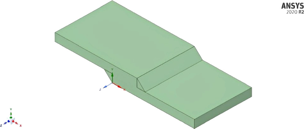
Figure 1. 3-D Model of Lap Joint.
Download figure:
Standard image High-resolution image3.3.2. Tee joint
Tee welding joints are formed when two pieces intersect at a 90° angle. This results in the edges coming together in the center of a plate or component in a 'T' shape. In this study, a tee weld joint is developed using 'Design Modeler' in ANSYS Workbench 2020 R2. The lap joint has two plates with dimensions 100 × 70 × 10. Figure 2, shows the model of tee joint.
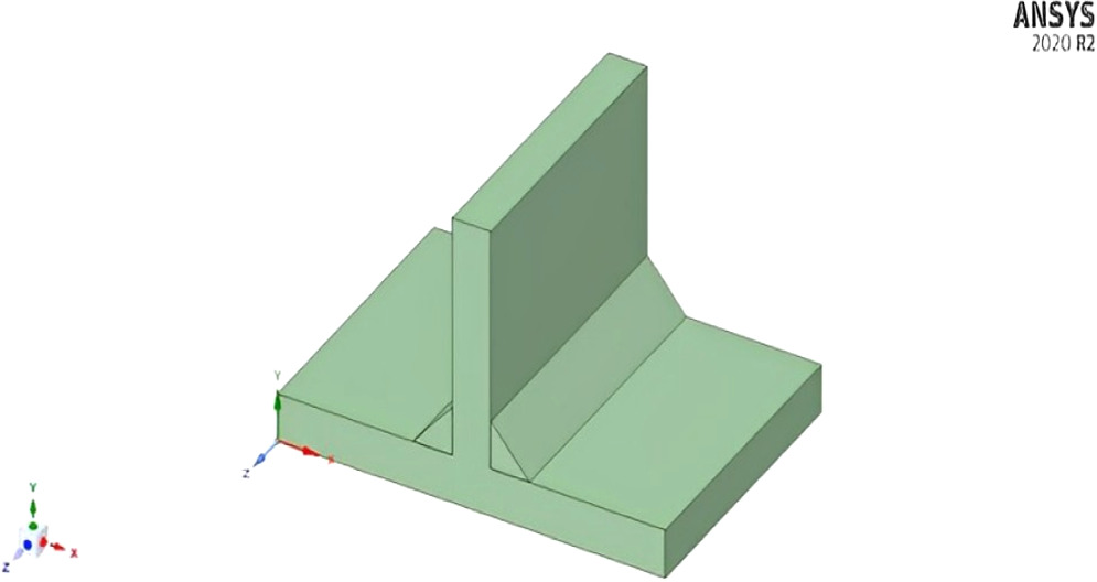
Figure 2. 3-D Model of Tee Joint.
Download figure:
Standard image High-resolution image3.4. Meshing of the finite element model
Meshing of the solid model is done by ANSYS Workbench 2020 R2. Mesh is discretizing the solid model into small elements. Solid model has number of points is called node which define its coordinate and degree of freedom. Combination of node create element.
3.4.1. Meshing for lap joint
Meshing done in Lap Joint shown in figure 3 done by ANSYS software. Element size is taken as 0.002 mm. Number of Nodes is 89310. Number of Elements is 18910.

Figure 3. Meshing done in lap joint.
Download figure:
Standard image High-resolution image3.4.2. Meshing for tee joint
Meshing done in Tee Joint shown in figure 4 done by ANSYS software. Element size is taken as 0.002 mm. Number of Nodes is 70366. Number of Elements is 14630.
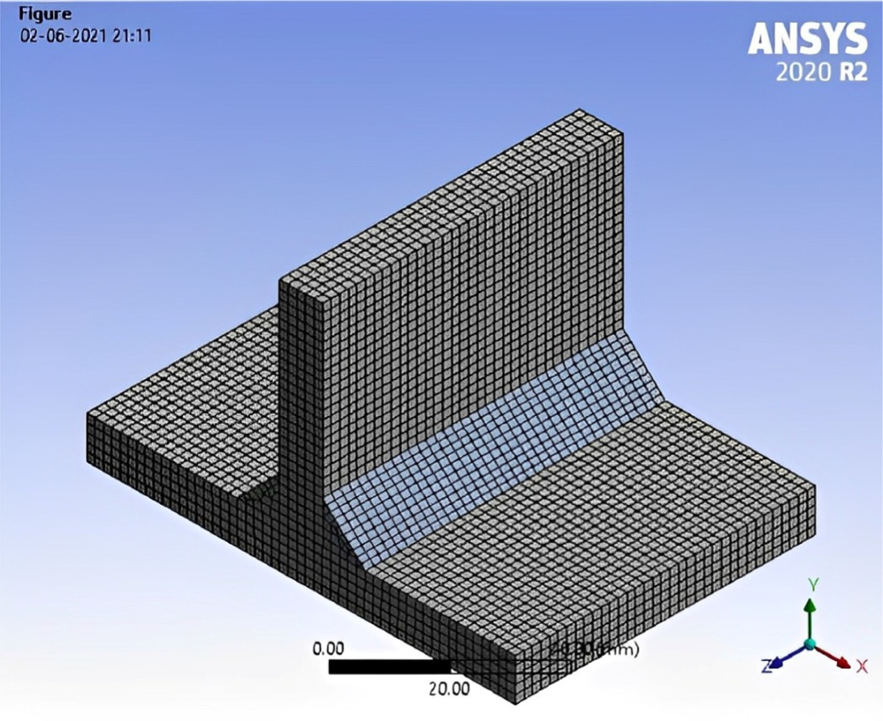
Figure 4. Meshing done in Tee Joint.
Download figure:
Standard image High-resolution image3.5. Boundary condition
ANSYS Workbench applies heat input to the weld joint through convection heat transfer across the entire body. The magnitude of this heat input is contingent upon the welding current and voltage, calculated by the formula: heat flow = voltage x current x efficiency. To examine the influence of welding current on various thermal outcomes, three distinct currents (140 amps, 150 amps, 160 amps) have been evaluated. The heat input is calculated using the relationship described in equation (2).

In the above relationship 'Q' is the heat input (in watt), 'η' is the arc efficiency, ' V' is the voltage (in volt), and 'I' is the source current. In this study, voltage as 30 volts and arc efficiency as 60% are used.
3.6. Convective heat transfer
Heat is applied by the convection mode. Then heat is transferred by the body to convection. Whole body surface is applied convection mode. Convective boundary condition given to Aluminum alloy shown in figure 5. For aluminum alloy the convective coefficient is 100 watt m−2k−1.
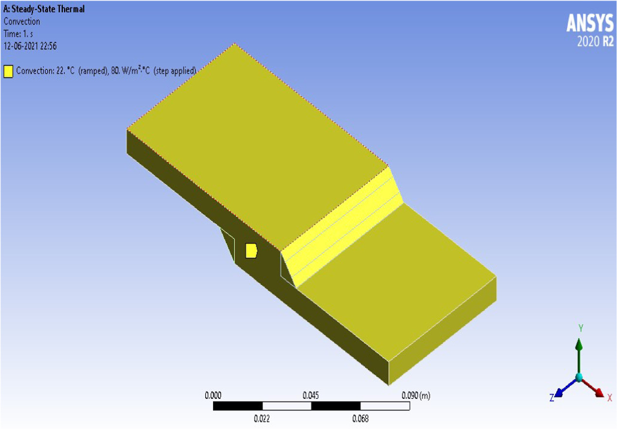
Figure 5. Convective boundary condition given to Aluminum alloy.
Download figure:
Standard image High-resolution image3.7. Steps to solve the model
Flowchart of the steps to solve the mode is illustrated in figure 6.
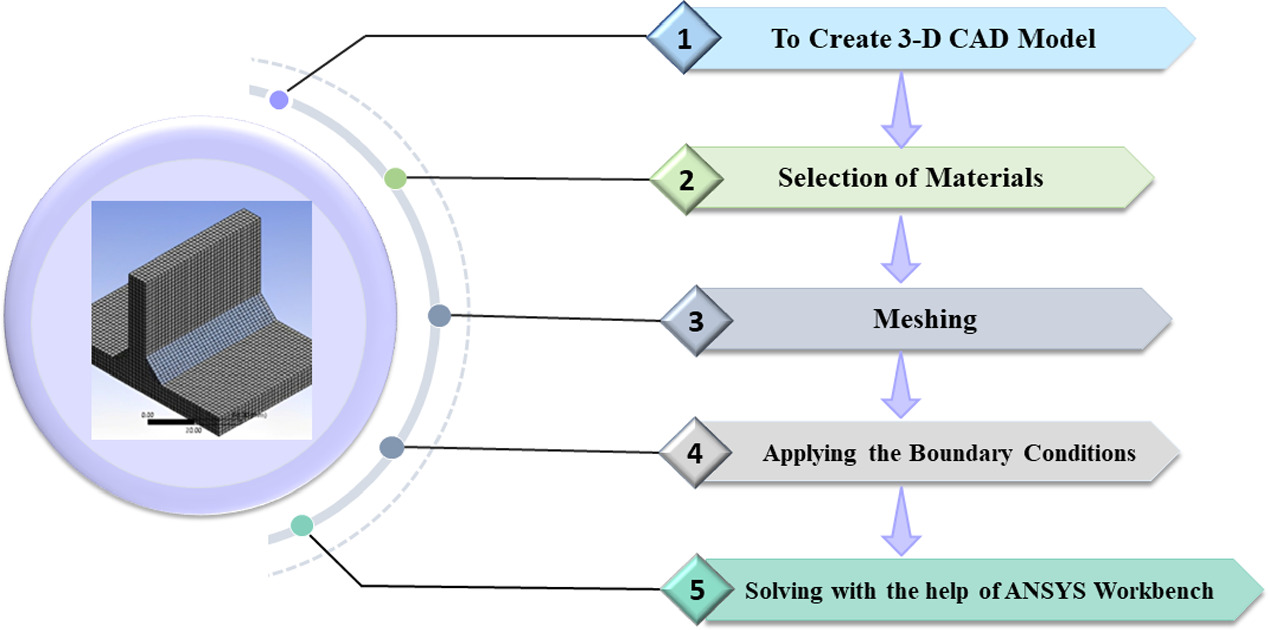
Figure 6. Flowchart of the steps to solve the mode.
Download figure:
Standard image High-resolution image4. Results and discussion
4.1. Maximum deformation of aluminium alloy for different heat flows in lap joint
At the heat flow of 2450 W for Aluminum alloy, the maximum deformation is 2.7338 mm, and the minimum is zero. At the heat flow of 2625 W for Aluminum alloy, the maximum deformation is 2.9292 mm, and the minimum is zero. At the heat flow of 2800 W for Aluminum alloy, the maximum deformation is 3.1245 mm, and the minimum is zero. With the increase in heat input, deformation increases. Maximum deformation occurred near the welding joint, and minimum deformation occurred near the fixed support. The total Deformation of aluminium alloy at 2450 W, 2625 W and 2800 W in the Lap joint is depicted in figure 7.
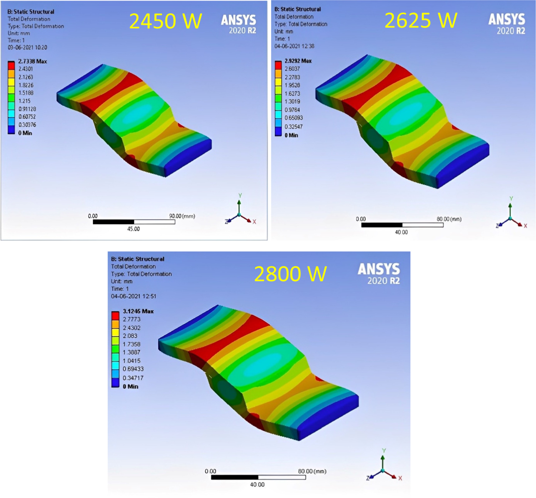
Figure 7. Total Deformation of aluminium alloy at 2450 W, 2625 W and 2800 W in Lap joint.
Download figure:
Standard image High-resolution image4.2. Equivalent elastic strain of aluminum alloy for different heat flow in lap joint
At the heat flow of 2450 W for Aluminum alloy, the equivalent elastic strain is 0.18906, and the minimum is 0.00040739. At the heat flow of 2625 W for Aluminum alloy, the equivalent elastic strain is 0.20256, and the minimum is 0.00043641. At the heat flow of 2800 W for Aluminum alloy, the equivalent elastic strain is 0.21607 mm, and the minimum is 0.00046551. With the increase in heat input, strain increases. Maximum equivalent elastic strain occurred in the edge of the fixed support and minimum equivalent elastic strain occurred on face of the plate. Equivalent elastic strain of aluminium alloy at 2450 W, 2625 W and 2800 W in Lap joint depicts in figure 8.
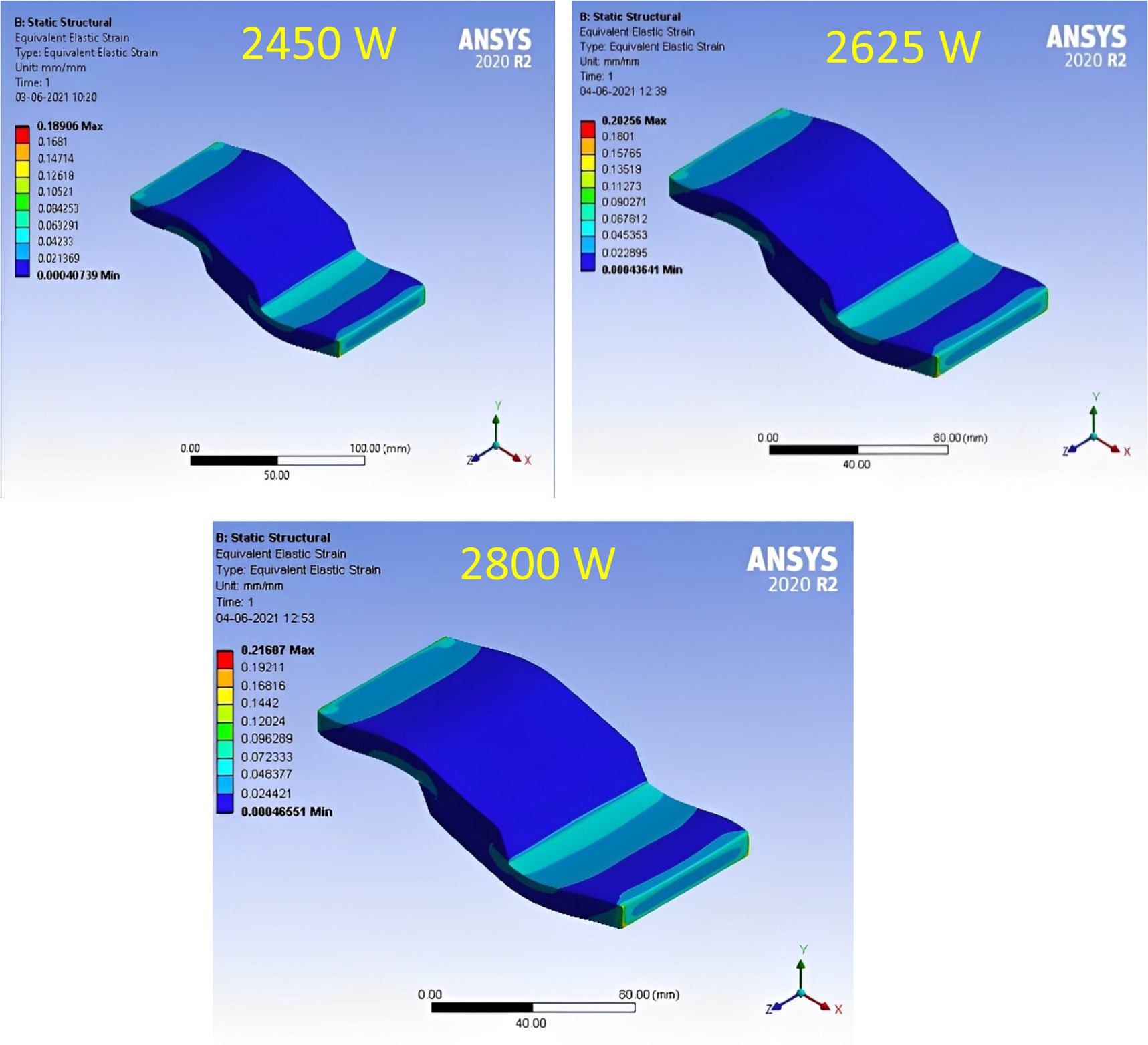
Figure 8. Equivalent elastic strain of aluminium alloy at 2450 W, 2625 W and 2800 W in Lap joint.
Download figure:
Standard image High-resolution image4.3. Equivalent stress of aluminum alloy for different heat flow in lap joint
At the heat flow of 2450 W for Stainless steel, the equivalent stress is 13423 MPa, and the minimum is 24.157 MPa. At the heat flow of 2625 W for Stainless steel, the equivalent stress is 14382 MPa, and the minimum is 25.868 MPa. At the heat flow of 2800 W for Stainless steel, the equivalent stress is 15341 MPa, and the minimum is 27.593 MPa. When the heat input increases, the value of stress increases. Maximum equivalent stress occurred on the edge of the fixed support, and minimum equivalent stress occurred on the face of the plate. The equivalent stress of aluminium alloy at 2450 W, 2625 W and 2800 W in the Lap joint is depicted in figure 9.

Figure 9. Equivalent stress of aluminium alloy at 2450 W, 2625 W and 2800 W in Lap joint.
Download figure:
Standard image High-resolution image4.4. Maximum deformation of aluminium alloy for different heat flow in lap joint
At the heat flow of 2450 W for Aluminium alloy, the maximum deformation is 1.8715 mm, and the minimum is zero. At the heat flow of 2625 W for Aluminium alloy, the maximum deformation is 2.0052 mm, and the minimum is zero. At the heat flow of 2800 W for Aluminium alloy, the maximum deformation is 2.1389 mm, and the minimum is zero. When the heat input is increased, the value of deformation increases. Maximum deformation occurred on near the welding joint and minimum deformation occurred on near the fixed support. Total Deformation of aluminium alloy at 2450 W, 2625 W and 2800 W in Lap joint depicts in figure 10.

Figure 10. Total Deformation of Aluminium alloy at 2450 W, 2625 W and 2800 W in Lap joint.
Download figure:
Standard image High-resolution image4.5. Equivalent elastic strain of aluminium alloy for different heat flow in tee joint
At the heat flow of 2450 W for Aluminium alloy, the equivalent elastic strain is 0.23998, and the minimum is 0.00011366. At the heat flow of 2625 W for Aluminium alloy, the equivalent elastic strain is 0.25712, and the minimum is 0.00012177. At the heat flow of 2800 W for Aluminium alloy, the equivalent elastic strain is 0.27427, and the minimum is 0.00012989. When the heat input is increased, the value of strain increases. Maximum equivalent elastic strain occurred on the edge of the fixed support, and minimum equivalent elastic strain occurred on the face of the plate. The equivalent elastic strain of Aluminium alloy at 2450 W, 2625 W and 2800 W in the Tee joint is depicted in figure 11.

Figure 11. Equivalent elastic strain of Aluminium alloy at 2450 W, 2625 W and 2800 W in Tee joint.
Download figure:
Standard image High-resolution image4.6. Equivalent stress of aluminium alloy for different heat flow in tee joint
At the heat flow of 2450 W for Stainless steel, the equivalent stress is 17039 MPa, and the minimum is 7.0606 MPa. At the heat flow of 2625 W for Stainless steel, the equivalent stress is 18256 MPa, and the minimum is 7.5649 MPa. At the heat flow of 2800 W for Stainless steel, the equivalent stress is 19473 MPa, and the minimum is 8.0691 MPa. When the heat input is increased, the value of stress increases. Maximum equivalent stress occurred on the edge of the fixed support, and minimum equivalent stress occurred on the face of the plate. The equivalent stress of Aluminium alloy at 2450 W, 2625 W and 2800 W in the Tee joint is depicted in figure 12.

Figure 12. Equivalent stress of aluminium alloy at 2450 W, 2625 W and 2800 W in Tee joint.
Download figure:
Standard image High-resolution image
5. Conclusions
In this work, computational simulation is carried out on aluminium alloy using Plasma Arc Welding. The metal plates utilized exhibit full convection, with varied input parameters such as a constant voltage while currents are adjusted. This analysis is performed to investigate and choose the suitable material where lower residual stress is developed. Also, stress, strain, and deformation are analyzed for all the materials in different heat flows.
- Keeping welding voltage is constant, simulation is done with three different welding currents of 140 amp, 150 amp and 160 amp. As welding current increases, heat input increases and more temperature is generated at the welding zone. Due to increase in the heat input, residual stress increase. Thus, maximum residual stresses are generated, when higher welding current is selected, which is 160 amp for present study.
- In lap joints, the highest stress and strain occur at the fixed support location, while the lowest stress and strain are observed at the plate face. The greatest deformation occurs near the welding joint.
- Residual stresses are unavoidable in welded joint. Under the same boundary conditions, the simulation of lap welding is done using Aluminium alloy.
- Under the same boundary conditions, simulation is done to two different joints, i.e., tee joint and lap joint made of aluminium alloy. Based on observations, it can be concluded that tee joints exhibit the highest von-Mises stresses, while lap joints demonstrate the lowest. Therefore, lap joints are considered safer compared to tee joints.
Data availability statement
All data that support the findings of this study are included within the article (and any supplementary files).