
Abstract
In the study high-velocity oxy-fuel thermal spraying to create Fe32Cr21Co21Al16Ti5B5 and Fe43Cr16Co12Al14Ti5B10, Fe32Cr21Co21Ni16Si5B5 and Fe43Cr16Co12Ni14Si5B10 coatings on Q235 steel substrates. Jet-type testing is used to examine the coatings' resistance to slurry wear. Researchers examined the surface to learn more about the erosion process. Taguchi analysis and a wear model confirm the significance of the selected important factors. The wear model's proposed mechanism shows remarkable agreement with the data. Coating loss may be attributed to several causes, including mixed ploughing, and cutting, platelet development, abrasion grooves, and cracking. The outcomes showed that the effect speed was the main contributing variable, the contribution ratio reached 65% to 70%, for the impact velocity of coating no 1 to 4. In contrast, it is recognized that impact velocity > impingement angle > erodent feed rate > erodent size is the most important sequence. Micro-cutting, mixed cutting, and ploughing were the essential disintegration systems for all coatings at low impingement points. In contrast, platelets were detected under normal impingement angles, as confirmed by SEM analysis. Both coatings seem to form passivation films, as shown by their greater Ecorr values relative to the substrate. Fe, Co, Cr, Al, and O all show up as peaks in XPS analyses.
Export citation and abstract BibTeX RIS
1. Introduction
From a materials perspective, the power generating sector is among the most difficult [1]. Extreme heat, chemical, and mechanical stress conditions are applied to the most vulnerable parts [2]. Consumption brought about by the effect of solid particles in a fluid on the outer layer of parts is called slurry disintegration. Sprinters, directing vanes, spouts, needles, the maze seal, and other hydro turbine parts are all vulnerable to slurry erosion [3, 4]. Applications like this need high-performance materials like superalloys or highly alloyed steels [5]. To prevent corrosion and extend the service life of components, surface coatings are generally recommended for hard materials [6]. This is because surface protective layers may minimize the cost of materials while simultaneously increasing the functional qualities of coated components [7]. When compared to hard chrome plating, physical vapour deposition (PVD), and chemical vapour deposition (CVD), thermal spray methods are preferred for applying coatings because of their versatility (they can be utilized on a wide assortment of materials), efficiency (they produce results quickly), economy, and low environmental impact [8–11].
Coatings may be applied to various materials to provide the necessary resistance to wear, corrosion, and friction [12]. Many different uses of the HVOF thermal spray method using WC-Co powders enhance steel bars' characteristics [13]. Coating technology advancement allows for individualized adaptation to harsh environments [14]. Successful applied to a broad grouping of materials, revealing minimal porosity, enhanced wear resistance, and increased hardness [15]. NiCrSiB coatings are often used where wear, oxidation, and hot opposition are required [16]. This is due to the coating's excellent mechanical [17], high temperature, tribological, and ecological effects [18]. Chromium is answerable for high-temperature consumption and oxidation security, and it reinforces alloys by generating a solid solution and forming M7C3 and M23C6 carbides [19]. The selection of alloying components is essential for improving microstructure and compound properties [2]. Mo and W have almost the same effect on materials, strengthening alloys and promoting the development of carbides and intermetallic stages despite the low carbon concentration. Adding Ni, C, and Fe boosts the fcc stage's stability at room temperature. In contrast, Cr, Mo, and W commonly normalize the hcp structure [20–22]. During HVOF process high particle temperature achieve around 1800 °C compared to HVAF process of around 1400 °C with the enhancing properties of porosity and adhesion strength [23–25]. Chromium dissolved in solid solution and increases the ability to protect with oxide layer [23, 26, 27].
The target of this investigation was to evaluate the wear obstruction and consumption opposition of a single experimental material and various commercially available materials. Mechanisms of slurry erosion, corrosion resistance, and XPS are studied. Despite the abundance of wear and XPS studies of thermally sprayed coatings, most focus on just a few types of erosion and wear. The comparison provided, backed by a large quantity of measured data, allows for a credible assessment of the utility of the most widely recognized surface medicines to shifting working circumstances.
2. Materials and methods
2.1. Materials used for substrates and coating
The base material was HV 355 Q235 steel, measuring 150 mm by 100 mm by 6 mm. Table 1 provides an analysis of the Q235 steel's chemical makeup. Powders of two absolute hardness values with standard granularity of 100–270 cross fragment and a little spot typically 1300 °C are investigated Fe32Cr21Co21Al16Ti5B5 (coating no 1) and Fe43Cr16Co12Al14Ti5B10 (coating no 2), Fe32Cr21Co21Ni16Si5B5 (coating no 3) and Fe43Cr16Co12Ni14Si5B10 (coating no 4). The iron-based powders were pre-applied on a 1 mm thick Q235 steel substrate surface and dried at 60 °C for two hours.
Table 1. Chemical composition of Q235 steel.
| Carbon (C) | Manganese (Mn) | Silicon (Si) | Sulphur (S) | Phosphorus (P) | Iron (Fe) |
|---|---|---|---|---|---|
| 0.17 | 0.08 | 0.37 | 0.039 | 0.036 | Balance within the mass percentage |
2.2. Coating procedure and characterization
Coatings are developed using a high-velocity oxidizing flame (HVOF) thermal spray technique. Coating deposition is complete at the rate of M/s. MEC (Metallizing Equipment Company) of Jodhpur, India. Powders of coating no 1, coating no 2, coating no 3, and coating no 4 were sprayed using high-velocity oxygen fuel (HVOF) thermal spraying as shown in figure 1; their smooth spherical surfaces indicate an entirely amorphous structure. Here are the settings for the spray gun as per requirement by operator and depends upon elements in the powders: Spraying at a distance of 350 mm, with a powder feed rate of 40 g min−1, and with an LPG flow rate of 55 SLPM and an oxygen flow rate of 270 SLPM. You may get the specifics of the spraying technique somewhere else [17].
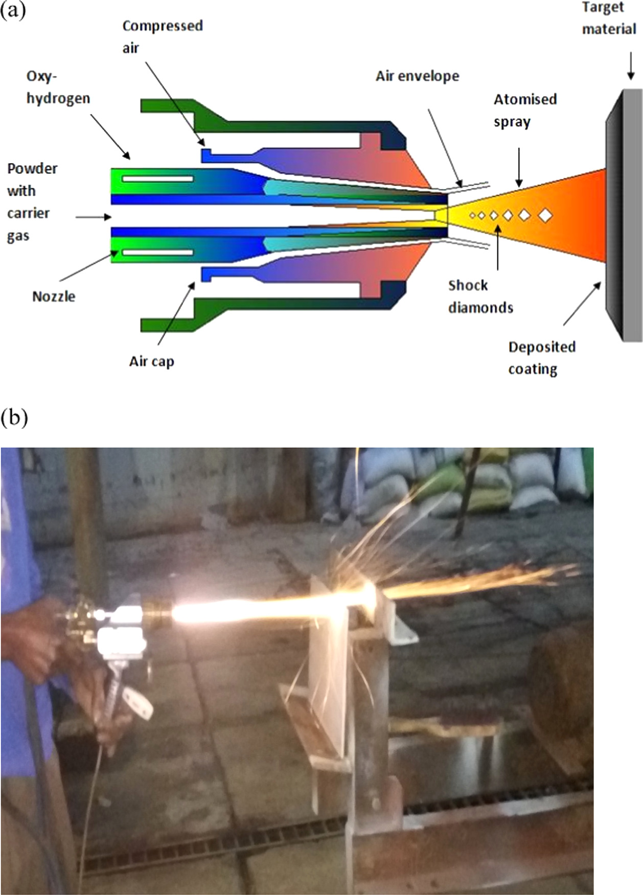
Figure 1. (a) and (b) Process of HVOF used for FeCrCoAlTiB/FeCrCoNiSiB deposition.
Download figure:
Standard image High-resolution image2.3. Slurry erosion analysis
The ASTM G-134 standard calls for erosive wear tests to be conducted utilizing a water stream disintegration test device (Model: TR-411, make: DUCOM, Bangalore, India). The examples were cleaned in an ultrasonically and dried when each test. (Make: Contech. Instruments Ltd.) instrument microbalances are used to weigh tests with an exactness of 0.1 mg. 15° to 90° samples at 15° point intervals are secured in the sample holder cavity containing the corrosion monitoring mechanism. All impact angles were performed using a 4 mm diameter with a distance of 50 mm between the tip and the nozzle surface. Three eroded samples' mean mass-loss figures are averaged out.
2.4. Optimization parameters
2.4.1. Exploratory design
The Taguchi approach is the highest quality level for plan techniques since it uses a predetermined table of array values to efficiently and systematically arrive at process optimization [28]. In this experiment, we use the Taguchi method to examine how different variables influence the coating's wear resistance. Table 2 shows how the significant factors that affect the wear by feed rate, impact velocity, impact angle, and erodent size. Therefore, the traditional L-16 orthogonal matrix is used to analyze the four control factors formulated at four levels, as illustrated in table 3. Minitab 16 is used to investigate change (ANOVA) to determine which factors fundamentally impacted the reaction parameters and under what circumstances the parameters performed best. To expose the quality of characteristics, the exploratory discoveries are transformed into signal-to-commotion proportion (SNR) once suitable level settings have been assigned. The erosive wear rate should be as low as feasible in coating wear analysis. Accordingly, the erosive wear rate is defined as [29]:
Table 2. Levels for various control factors.
| Control factor | I | II | III | IV | Units |
|---|---|---|---|---|---|
| A: Impact velocity | 10 | 20 | 30 | 40 | m/s |
| B: Impingement angle | 30 | 45 | 60 | 75 | Degree |
| C: Erodent feed rate | 160 | 195 | 230 | 265 | g/min |
| D: Erodent size | 105 | 125 | 149 | 180 | lm |
Table 3. L-16 experimental design.
| Experiment no. | A: Impact velocity | B: Impingement angle | C: Erodent feed rate | D: Erodent size |
|---|---|---|---|---|
| 1 | 10 | 30 | 160 | 105 |
| 2 | 10 | 45 | 195 | 125 |
| 3 | 10 | 60 | 230 | 149 |
| 4 | 10 | 75 | 265 | 180 |
| 5 | 20 | 30 | 195 | 149 |
| 6 | 20 | 45 | 160 | 180 |
| 7 | 20 | 60 | 265 | 105 |
| 8 | 20 | 75 | 230 | 125 |
| 9 | 30 | 30 | 230 | 180 |
| 10 | 30 | 45 | 265 | 149 |
| 11 | 30 | 60 | 160 | 125 |
| 12 | 30 | 75 | 195 | 105 |
| 13 | 40 | 30 | 265 | 125 |
| 14 | 40 | 45 | 230 | 105 |
| 15 | 40 | 60 | 195 | 180 |
| 16 | 40 | 75 | 160 | 149 |
2.5. Electrochemical corrosion testing
The Q235 steel substrate was also subjected to corrosion testing as a standard. The electrode area was reduced to 1 cm2 by sealing the specimens with epoxy glue before the electrochemical corrosion test. After that, we cleaned and ultrasonically cleaned the cathode with ethanol and dried it; then, we ground its surface using progressively finer grits of waterproof SiC grating paper (from 180 to 2000 grit). Electrochemical corrosion experiments were conducted in a 3.5 Wt% NaCl arrangement at room temperature. Using a three-electrode setup, we found that using a reference electrode made of saturated calomel and an auxiliary electrode made of platinum wire produced the most accurate results. The graphs used Tafel extrapolation to obtain corrosion potential (Ecor) and corrosion current density (Jcor).
2.6. X-ray photoelectron spectroscopy (XPS)
At pass energy of 20 eV, x-ray photoelectron spectroscopy (XPS) was used to investigate the elemental chemical valence states of the negative films under applied formation potentials. CasaXPS (CasaXPS version 2.3.18PR1.0) fit the compositions' spectra against a Linear and Shirley background. The usual peak correction function had previously been applied to all the peaks in the exemplary spectra (C 1s, 284.8 eV). In addition, sculpting with XPS was utilized to quantify the thickness of the independent film.
3. Results, analysis, and discussion
3.1. Microstructure and phase constitution
The XRD example of the top surface of the covering is displayed in figure 2. The cover comprises a mixture of amorphous and crystalline structures. Crystal peaks were analyzed and recognized as vital arrangement stages, for example, bcc strong arrangement CoFe15.7, fcc strong arrangement (Fe, Al) and (Fe, Al) (Fe, Ni). The substrate adjacent to the interface contains bcc solid solution phases (Co, Fe), solid solution phases (Fe, Al), and solid solution phases (Fe, Ni), as well as borides and carbonate compounds. The amorphous/glasslike layer comprises 39% indistinct stage, 49% fcc (Fe, Al) stage, and 49% fcc (Fe, Ni) phase. As seen in, the solid solution phases contain a variety of precipitates, including (Co, Fe) carbides and borides [30].

Figure 2. X-ray diffraction patterns for the HVOF sprayed coatings on Q235 steel substrate (a) coating no 1 (b) coating no 2 (c) coating no 3 (d) coating no 4.
Download figure:
Standard image High-resolution image3.2. Parametric analysis of erosive wear performance
The discoveries showed that the erosive wear rate of coating no 1, coating no 2, and coating no 3, coating no 4 was different for each of the authorised experimental trials. The outcomes showed that the erosive wear rate for all the coatings varied from 0.0004 to 0.0012 g kg−1. When testing erosive wear rates, experiment no. 1 yields the lowest values for all the coatings at 10 m s−1 influence speed, 30° impingement point, 160 g min−1 erodent feed rate, and 105 lm erodent size. Besides, the most extreme wear rates at an effective speed of 40 m s−1, an elastic point of 60°, a disintegration feed rate of 265 g min−1, and an erodent size of 180 lm in experiment number 15. Most extreme and least SNR values (SNRmax _SNRmin) for all control factors are given in table 4.
Table 4. Response table for SNR on erosive wear rate of coating no 1, coating no 2 coating no 3 and coating no 4.
| Control factors | |||||
|---|---|---|---|---|---|
| Level | A | B | C | D | |
| A | 1 | 4.8610 | 4.6973 | 2.5527 | 2.4606 |
| AverageSNR(dB) | 2 | 3.4426 | 0.7704 | 2.3712 | 1.9717 |
| 3 | 0.9862 | 1.8490 | 2.0791 | 2.2115 | |
| 4 | −0.6899 | 1.2832 | 1.5969 | 1.9561 | |
| SNRmax—SNRmin | 5.5509 | 3.9269 | 0.9559 | 0.5045 | |
| 1 | 2 | 3 | 4 | ||
| B | 1 | 4.6862 | 4.4088 | 2.3304 | 2.3545 |
| AverageSNR(dB) | 2 | 3.3137 | 0.8724 | 2.0987 | 1.7800 |
| 3 | 1.0992 | 1.7952 | 2.0611 | 2.2132 | |
| 4 | −0.7580 | 1.2646 | 1.8508 | 1.9933 | |
| SNRmax—SNRmin | 5.4443 | 3.5363 | 0.4797 | 0.5745 | |
| 1 | 2 | 4 | 3 | ||
| C | 1 | 0.5800 | 0.6275 | 0.8150 | 0.8100 |
| AverageSNR(dB) | 2 | 0.6900 | 0.9200 | 0.8075 | 0.8100 |
| 3 | 0.8875 | 0.8275 | 0.8125 | 0.8150 | |
| 4 | 1.0875 | 0.8700 | 0.8100 | 0.8100 | |
| SNRmax—SNRmin | 0.5075 | 0.2925 | 0.0075 | 0.0050 | |
| 1 | 2 | 3 | 4 | ||
| D | 1 | 5.0103 | 4.4981 | 2.3995 | 2.4797 |
| AverageSNR(dB) | 2 | 3.3889 | 0.9909 | 2.3118 | 1.9845 |
| 3 | 1.1147 | 1.9792 | 2.1862 | 2.3845 | |
| 4 | −0.6776 | 1.3680 | 1.9387 | 1.9875 | |
| SNRmax—SNRmin | 5.6878 | 3.5072 | 0.4608 | 0.4951 | |
| 1 | 2 | 4 | 3 | ||
The impingement angle has the second-greatest effect after the impact velocity. Increasing the effect speed from 10 m s−1 causes the mean SNR to drop (figures 3(a), 4(a), 5(a), 6(a)), suggesting an erosive wear rate rise. The greater impact velocity of the erodent particles is likely to blame for this outcome since it increases the energy they impart to the coating when they strike the samples [31]. Figures 3(b), 4(b), 5(b), and 6(b) show that when the impingement angle rises above 30°, the mean SNR falls, indicating an expansion in the erosive wear rate. It is in like way found that the erosive wear rate is more major at an impingement point of 60° for both covered models. This is because the tangential component has a more dramatic influence than the normal component at an impingement angle of 60° degrees. The common SNR drops as erodent feed rate and erodent size move, as displayed in figures 3(c) and (d), 4(c) and (d), 5(c) and (d), and 6(c) and (d), showing that erosive wear rate increases. The erosive wear of samples tends to rise as the erodent feed rate increases. This allows a greater number of particles to raise around the sample of the examples as the erodent size increases, which might bring about more prominent energy. The wear rate was shown to rise continuously with the square of the impact velocity and the cube of the erodent size. Findings corroborate those of the published studies [32, 33]. Furthermore, it is shown that the impact velocity has a 65% to 70% contribution ratio on the erosive wear rate for coating no 1 to 4 and have minimal erosive wear rate contributions from erodent feed rate and erodent size, at around 2% and 1%, individually. As shown in table 5, the erosive wear rate of coating no 3 and coating no 4 is only little affected by the erodent feed rate and erodent size, each by less than 1%.
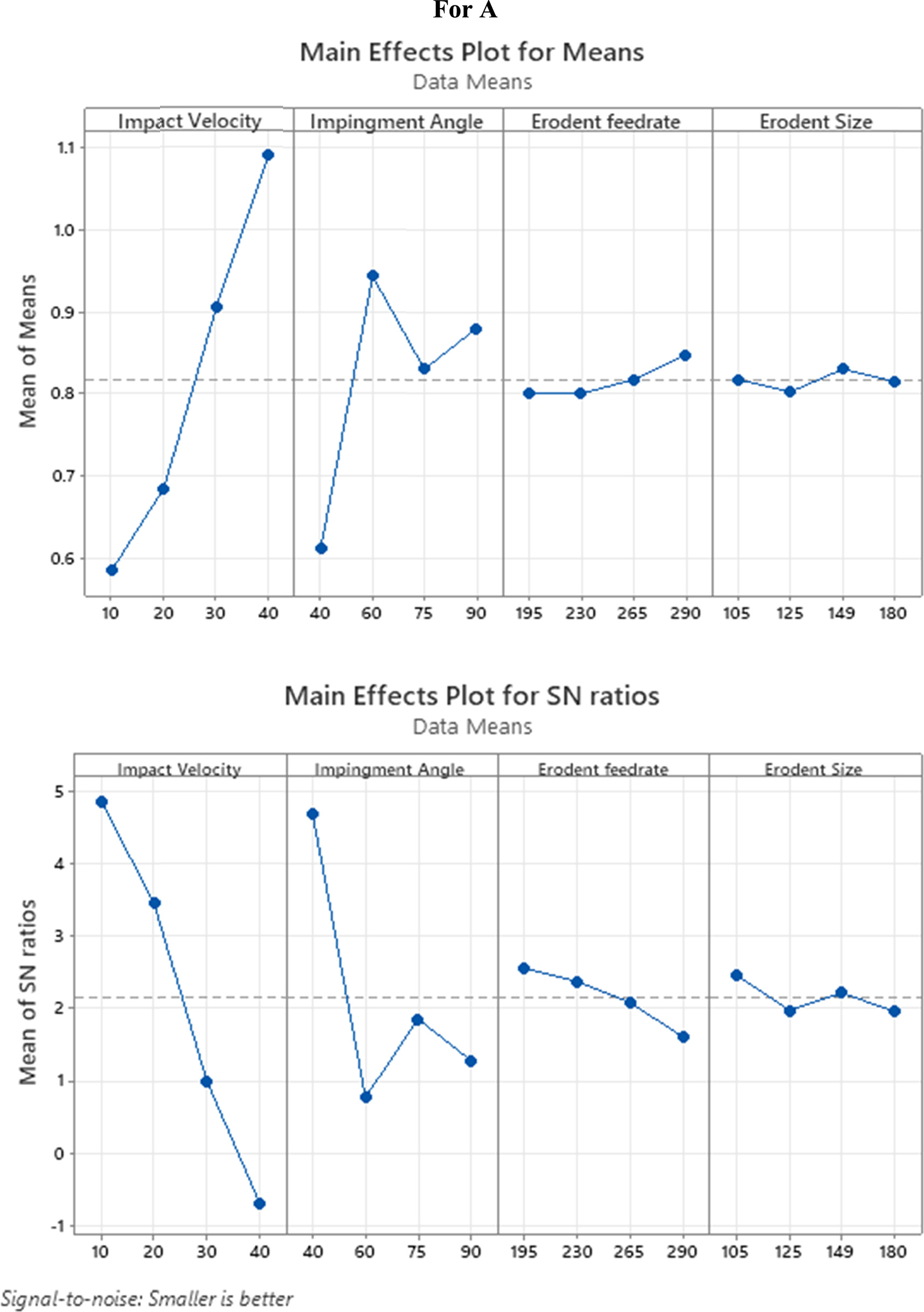
Figure 3. Effect of control factors on the erosive wear rate of coating no 1.
Download figure:
Standard image High-resolution image
Figure 4. Effect of control factors on the erosive wear rate of coating no 2.
Download figure:
Standard image High-resolution image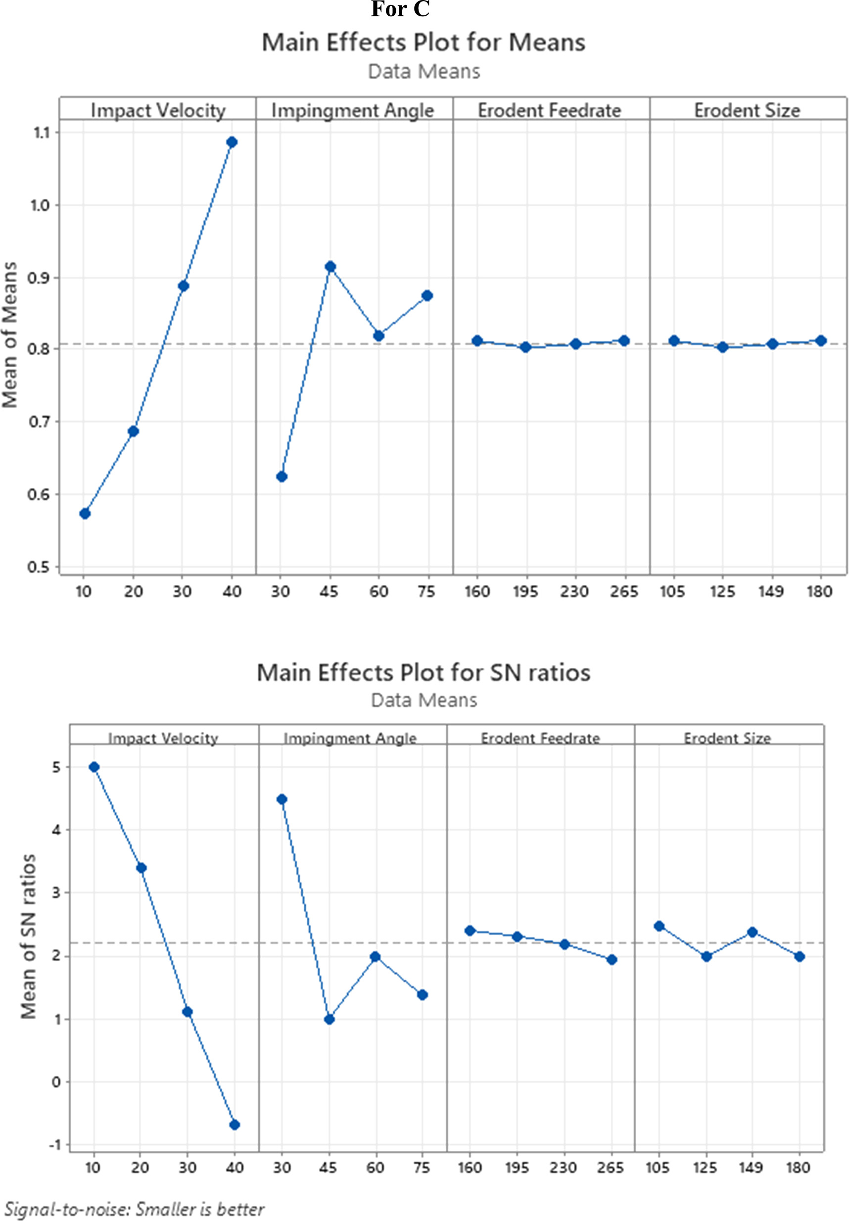
Figure 5. Effect of control factors on the erosive wear rate of coating no 3.
Download figure:
Standard image High-resolution image
Figure 6. Effect of control factors on the erosive wear rate of coating no 4.
Download figure:
Standard image High-resolution imageTable 5. Contribution of control factors on erosive wear rate coating no 1, coating no 2 coating no 3 and coating no 4.
| Source | DF | Seq SS | Adj SS | Adj MS | F | %C |
|---|---|---|---|---|---|---|
| A | ||||||
| Impact Velocity | 3 | 73.759 | 73.7589 | 24.5863 | 640.01 | 65.00 |
| Impingement Angle | 3 | 36.935 | 36.9353 | 12.3118 | 320.49 | 32.50 |
| Erodent feed rate | 3 | 2.088 | 2.0883 | 0.6961 | 18.12 | 1.840 |
| Erodent Size | 3 | 0.679 | 0.6786 | 0.2262 | 5.89 | 0.598 |
| Residual Error | 3 | 0.115 | 0.1152 | 0.0384 | ||
| Total | 15 | 113.576 | ||||
| B | ||||||
| Impact Velocity | 3 | 69.323 | 69.3225 | 23.1075 | 168.20 | 68.59 |
| Impingement Angle | 3 | 30.509 | 30.5092 | 10.1697 | 74.02 | 30.18 |
| Erodent Feed rate | 3 | 0.463 | 0.4634 | 0.1545 | 1.12 | 0.456 |
| Erodent Size | 3 | 0.762 | 0.7620 | 0.2540 | 1.85 | 0.754 |
| Residual Error | 3 | 0.412 | 0.4122 | 0.1374 | ||
| Total | 15 | 101.469 | ||||
| C | ||||||
| Impact Velocity | 3 | 75.077 | 75.0766 | 25.0255 | 213.66 | 70.61 |
| Impingement Angle | 3 | 29.936 | 29.9359 | 9.9786 | 85.20 | 28.16 |
| Erodent Feed rate | 3 | 0.482 | 0.4818 | 0.1606 | 1.37 | 0.452 |
| Erodent Size | 3 | 0.814 | 0.8140 | 0.2713 | 2.32 | 0.766 |
| Residual Error | 3 | 0.351 | 0.3514 | 0.1171 | ||
| Total | 15 | 106.660 | ||||
| D | ||||||
| Impact Velocity | 3 | 72.361 | 72.3608 | 24.1203 | 158.35 | 70.10 |
| Impingement Angle | 3 | 29.632 | 29.6315 | 9.8772 | 64.84 | 28.70 |
| erodent Feed rate | 3 | 0.351 | 0.3513 | 0.1171 | 0.77 | 0.340 |
| Erodent Size | 3 | 0.870 | 0.8704 | 0.2901 | 1.90 | 0.841 |
| Residual Error | 3 | 0.457 | 0.4570 | 0.1523 | ||
| Total | 15 | 103.671 |
3.3. Observation of eroded surfaces
7 and 8 in the Figures Close inspection of the photos reveals that the material loss at the 30° and 45° impingement angle results from micro-cutting, blended cutting, and abrasion grooves by sporadically formed erodent particles. [1] Have contended that cutting and abrasion grooves at a low impingement point was the primary way of material removal due to the effect of irregular particles. Figure 7 shows micro-cuts and a combination of cutting and ploughing marks. The effect forces' normal part is deficiently huge compared with the digressive component at low impingement angles. The material's hardness is a critical part of mitigating these deformation processes.
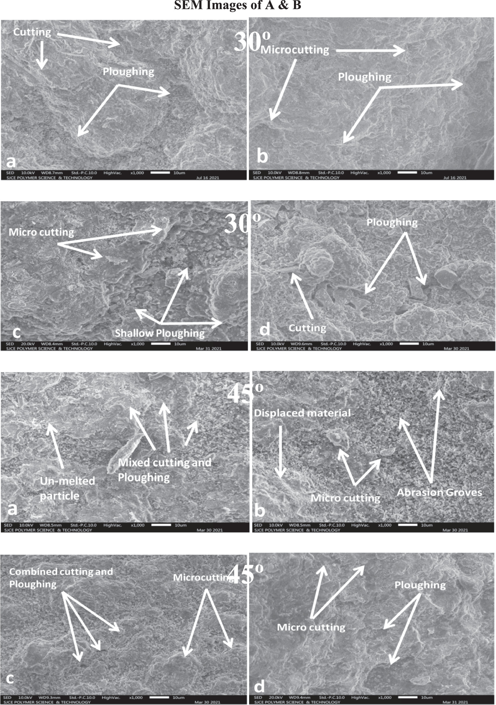
Figure 7. The eroded surface SEM micrographs of coating no 1 and coating no 3 (a), (c) and coating no 2 and coating no 4 (b), (d) coatings after slurry Erosion at 300 and 450 impingement angle.
Download figure:
Standard image High-resolution imageThe material's hardness is vital in resisting various deformation processes. Many distorted platelets and indentations were visible on the eroded surfaces, starkly contrasting the hardness that had been measured. Impact sand grains indented the forming platelets. The extruded material from the craters tends to flow outward and aggregate in the shape of platelets around the perimeter. A series subsequently provide it of successive typical impacts from the sand particles. Coating no 1 to 4 shows considerable strain hardening at the severely distorted surfaces at 60° and 75° impingement. Platelet generation and removal at normal impingement angle is the primary erosion process for all the coatings. SEM micrographs of damaged coatings at 60° and 75° impingement angle are shown in figure 8. Insufficient coating ductility manifests as flattened lipping. It appears that the coatings were additionally taken out by fragile cracks, as shown by the presence of specific gaps. Repetition of particle impact causes energy transfer, which in turn causes a fatigue process at or near normal incidence for brittle materials and strain hardening occurs due to trapping of dislocations by the oxides in coatings [34]. High hardness and low ductility meant that coatings quickly embrittled under the constant impact of eroding particles. In this situation, erosion of all the coatings at 60° and 75° impingement are accomplished by repeated plastic deformation and brittle fracture due to irregular interaction with eroded particles as particles themselves strike as they returns back with coming ones.
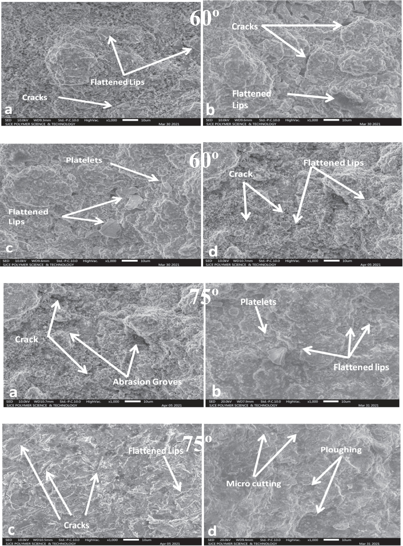
Figure 8. The eroded surface SEM micrographs of coating no 1 and coating no 3 (a), (c) and coating no 2 and coating no 4 (b), (d) coatings after slurry Erosion at 600 and 750 impingement angles.
Download figure:
Standard image High-resolution image3.4. Polarization results
Testing the specimens' corrosion resistance using potentiodynamic polarisation yielded the findings shown in figure 9. From the point where the tangents of the anodic and cathodic Tafel bends associate, we were able to extrapolate the corresponding slopes of the anodic and cathodic Tafel plots individually. Extricated from the polarization bends, the corrosion fitting parameters Ecorr and Jcorr are shown in table 6. Under the same corrosion conditions, the No. 1 coating has a positive Ecorr worth of − 0.64 V, the No. 2 coating has a positive Ecorr worth of − 0.54 V, the No. 3 coating has a positive Ecorr worth of − 0.60 V, and the No. 4 coating has a positive Ecorr worth of − 0.60 V; that is, the No. 2 coating has most elevated corrosion opposition contrasted with the other coatings due increase in percentage of boron as small size atom fitted in the gap and form dense structure. Furthermore, the synergistic effect of lower porosity result in the best corrosion resistance of coating no.2 [35].

Figure 9. Potential dynamic polarization curves of the coatings and substrate in a 3.5 wt% NaCl solution.
Download figure:
Standard image High-resolution imageTable 6. Corrosion parameter fitting results from the corrosion polarization curves.
| Sample | ECORR (V versus SCE) | JCORR(μA cm−2) | βa (V dec−1) | −βc (V dec−1) |
|---|---|---|---|---|
| COATING No.1 | −0.64 | 0.267 | 17.26 ± 0.73 | 20.27 ± 0.32 |
| COATING No.2 | −0.54 | 0.151 | 12.95 ± 0.48 | 26.73 ± 0.43 |
| COATING No.3 | −0.60 | 0.116 | 13.77 ± 1.25 | 9.84 ± 1.53 |
| COATING No.4 | −0.60 | 0.253 | 30.30 ± 1.46 | 25.14 ± 0.55 |
| SUBSTRATE | −0.66 | 0.260 | 19.05 ± 0.53 | 22.26 ± 0.45 |
3.5. XPS analysis of surface
The science of a material's surface might be inspected utilizing X-beam photoelectron spectroscopy (XPS), occasionally called electron spectroscopy for compound examination (ESCA). The atomic chemical and electronic states and elemental composition may be determined by using XPS. For the vast majority of elements, x-ray photoelectron spectroscopy (XPS) is now a standard technique for deciding the compound state of a sample. Databases of binding energies may make it difficult to determine which chemical conditions are present. However, these databases do not give critical fitting parameters for complicated, blended metal and metal oxide frameworks, like pinnacle widths and deviations.
Fe, Co, Cr, Al, and O all show up in the spectrum, but the C peak indicates the inevitable air pollution. Energy spectra measurements show that oxide films have illustrated on the covering surfaces of coating no 1, coating no 2, and coating no 3, and coating no 4 [36].
In figures 10(a) and 11(a), we see the binding energies of Peak 1, Peak 2, and Peak 3 (710.19 eV, 715.67 eV, and 723.59 eV) of the great goal spectra of Fe 2p on the coating no 1 surface passivation films [37]. The chemical species Fe (III), Fe (O) b, and Fe [1] are associated with the two binding energies. The coating has two peaks at 783.508 eV, corresponding to Co (0) b. What's more, the other at 785 eV relating to Co (sat.) (An unanalyzed companion peak) [38]. The two extremes of the C spectrum, at 285.24 and 288 eV, represent the binding energy components of C [1] and C [2], respectively.

Download figure:
Standard image High-resolution image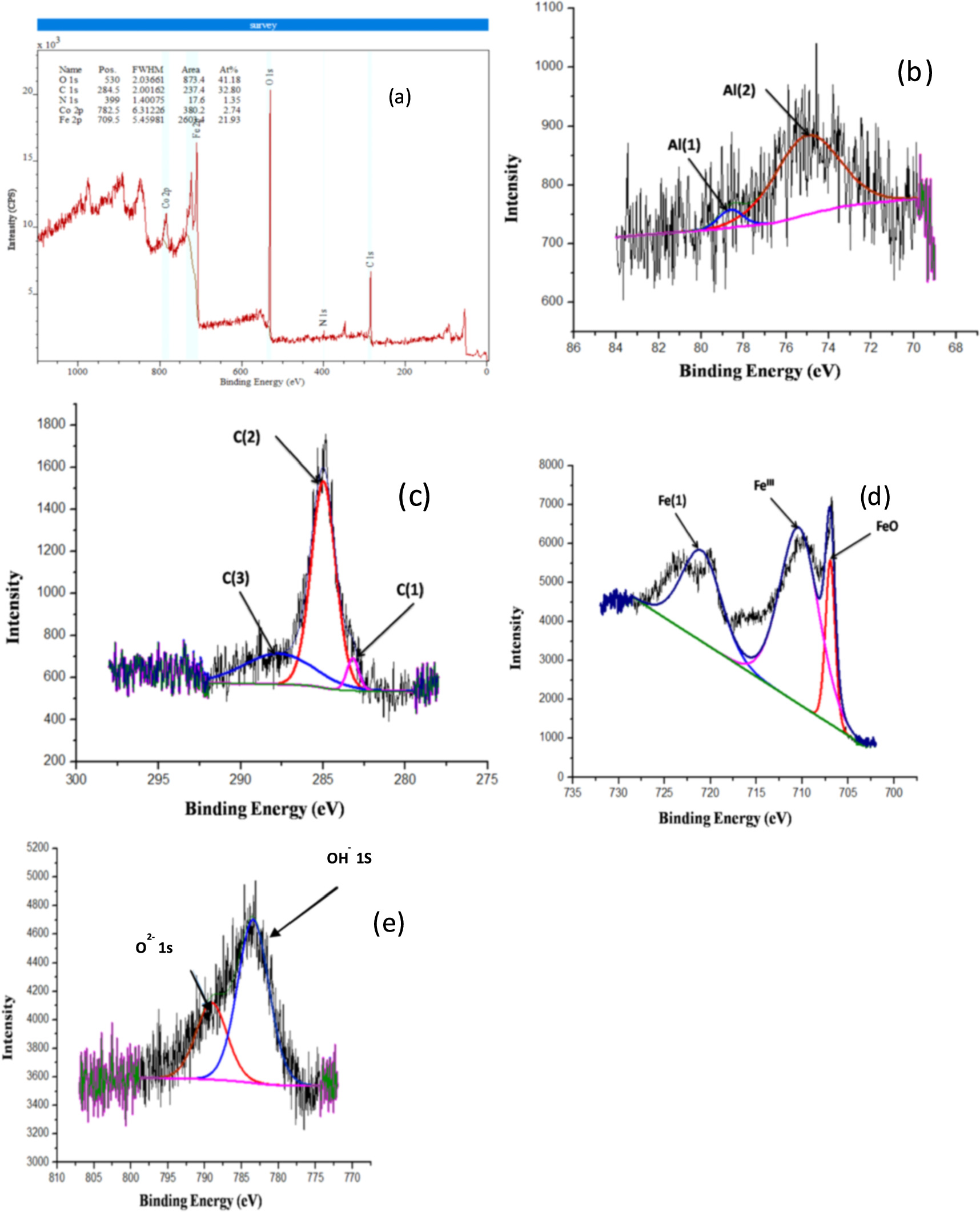
Figure 10. High-resolution XPS pattern of the passivation film on coating no 1. (a) suevey spectrum; (b) C (1), C (2); (c) Co 2p; (d) Fe 2p; (e) O 1s detail spectrums coating no 2. (f) suevey spectrum; (g) Al (1), Al (2); (h) C (1), C (3); (i) Fe 2p; (j) O 1s detail spectrums.
Download figure:
Standard image High-resolution imageIn the high-goal spectra of Fe 2p on a superficial level passivation film of coating no 2, the binding energies of Peaks 1, 2, and 3 are 706, 710, and 721 eV, respectively [34]. Fe (0) b and Fe (III) are the corresponding chemical species for the two binding energies. Co 2p spectra of the two peaks are shown for coating no 2 [22], with the 789.315 eV peak corresponding to Co (OH)2 and the 783.27 eV peak corresponding to Cosat (an unanalyzed companion peak). The two C spectrum peaks at 283.13.24 eV and 285.012 eV correspond to the binding energies of C [1] and C [2], respectively. Al [1] and Al [2] have peaks at 74.83 and 78.62 eV, respectively [39].
High goal spectra of Cr 2p3/2 on a superficial level passivation film of coating no 3 and coating no 4 are shown in figures 10(b) and 11(b), revealing binding energies of 578 eV and 580.3 eV, respectively. Cr2O3 and Cr (OH)3 are the chemical species that correspond to these two binding energies [40]. The two coatings' Co 2p3/2 spectra are displayed in figures 10(c) and 11(c); the top at 780.7 eV is credited to Co3+, though the shelter at 785 eV is credited to Cosat (an unanalyzed companion peak) [41]. Similar findings were obtained in coating no 4, as shown in figures 10(d) and 11(d), which portray the limiting energy parts of the Fe 2p3/2 range on the movies at 712 eV and 714 eV separately [42]. According to the iron species deconvolution data, iron hydroxide is the primary part of the passivation movies of the two coatings. Ni 2p3/2 spectra of the films of the two coatings are displayed in figures 10(e) and 11(e); the top at 858.7 eV has a place with Ni (OH)2, and the top at 861.2 eV alludes to Nisat (Unanalyzed companion peak) [43][44]. Films on coating no 3 and coating no 4 provide O1s spectra that can be broken down into two groups (figures 10(f) and 11(f)). Oxides of Cr and Fe are the most common forms of O2- species (531.2 eV). The OH- species in the film, which are present as metal hydroxides, are represented by the peak at 532.8 eV.

Download figure:
Standard image High-resolution image
Figure 11. High-resolution XPS pattern of the passivation film on coating no 3. (a) suevey spectrum; (b) C (1), C (2); (c) Co 2p; (d) Fe 2p; (e) O 1s detail spectrums. For coating no 4. (f) suevey spectrum; (g) C (1), C (2); (h) Co 2p; (i) Fe 2p; (j) O 1s detail spectrums.
Download figure:
Standard image High-resolution image
4. Conclusion
HVOF spraying of coating no 1, coating no 2, coating no 3 and coating no 4 resulted in a unique substrate layer and branch coating. The base layer adjoining the connection point is made of bcc (Co, Fe) solid solution phases, solid solution phases (Fe, Ni), boride, and carbonized compounds. In contrast, the amorphous/crystalline layer comprises a 39% amorphous phase. And fcc phase (Fe, Al), 49%, and fcc (Fe, Ni) phase. Among the solid solution phases (Co, Fe), precipitates containing carbides and borides are evenly dispersed. Erosion is the primary wear process of the amorphous/crystalline layer, while oxidation is the primary corrosion mechanism of the dendritic layer.
Impact Speed>Impact Angle>Erodent feed rate>Erodent size dominates the erosion rate of coating no 1 and coating no 3 while Impact Speed>Impact Angle> Erodent size> Erodent feed rate dominates the erosion rate of coating no 2 and coating no 4.
Contribution ratios of the aforementioned control factors to the erosive wear rates of dominates the erosion rate of coating no 1 is 65, 32.5, 1.84, and .598%; coating no 2 is 68.59, 30.18, .456, and .754 percent; coating no 3 is 70.61, 28.16, .452, and .766%; coating no 4 is 70.10, 28.70,.340, and.841 percent.
The main effect plot reveals that for all the coatings the optimum level to provide minimum erosive wear rate is a 10 m s−1, 30°, 160 g min−1, and 105 lm for a combination of impact velocity, impact angle, feed rate, and erodent size.
The OCP indicates that Fe-based coatings grow nobler with time and are resistant to pitting corrosion when submerged in a 3.5 wt% NaCl solution. Passivation layers have been formed by the all coatings, as shown by their more excellent Ecorr value compared to the substrate.
Data availability statement
The authors confirm that the data supporting the findings of this study are available within the article [and/or] its supplementary materials.
Funding
No funding from any agency or others.
Ethical approval
This is an observational study. Research Ethics Committee has confirmed that no ethical approval is required.
Consent to publish
No participation of human is involve in the current studyand thus, no consent to publish is required.