
Abstract
Holography is a technique to record and reconstruct three dimensional (3D) information without mandating lenses. Digital holography (DH) provides direct access to the complex amplitude of the reconstructed wavefront. This feature differentiates DH from other imaging techniques and enables it to provide quantitative information of the object under investigation. Advancements in technologies of digital image sensors, coherent sources, and computation algorithms and hardware, has paved the way of digital holographic systems for industrial applications. This work presents an overview of the scientific and industrial applications where DH can play an important role. Few of the applications of digital holographic systems in the industrial and scientific areas including microscopy, non-destructive testing, displays, environment, cloud and ocean studies are discussed.
Export citation and abstract BibTeX RIS
1. Introduction
Holography [1] is an optical technique for wavefront recording and reconstruction. In 1948 Gabor invented holographic principle while working on the improvement of electron microscopy [2]. Due to non-availability of coherent light source, it could not progress well at that time. In 1960 laser was invented, which was immediately used in holography in 1962 by Leith and Upatnieks and introduced the concept of off-axis holography [3] from the works on the side looking synthetic aperture radar. The off-axis holography successfully solved the problems of overlap of reconstructed image, conjugate image and direct beam related with Gabor's in-line holography. The concept of off-axis recording also enabled holography to record holograms of diffuse and opaque objects and thus extended its usefulness to many new areas of research and industrial applications [4]. Around the same time in 1962, Russian physicist YN Denisyuk reported single beam reflection holography where holograms can be reconstructed in natural colors [5].
The revolution in digital technologies and their amalgamation with holographic principle [6, 7] further opened doors for applications of holography in new areas, which were not possible with conventional holographic techniques, such as direct access and digital manipulation of phase of reconstructed wavefront. Before amalgamation of digital technologies (such as low cost image sensors: charge-coupled device (CCD)/ complementary metal oxide semiconductor (CMOS) and wide availability of affordable and powerful personal computers) in recording of holograms and processing of reconstructed wavefronts from digital holograms, the applications of holography were mostly confined to academic interest except only few commercial, scientific and industrial applications. The access to high resolution digital recording and reconstruction devices [e.g., Spatial light modulators (SLM)/Digital micromirror device (DMD)] alongwith cost-effective personal computer (PC) and development of powerful algorithms and software and compact coherent sources fuelled the process of development of portable digital holographic systems and instruments and exploration of their applications in until unexplored areas of research and consumer products.
Applications of holography can be broadly divided based on its use for imaging or interferometry. Single hologram based techniques are generally suitable for imaging, display and diagnostic applications. In these schemes, wavefront reconstructed from the hologram can be used to generate images of the object under study. These holographic images can be used for displays [8], microscopy [9], imaging [10, 11], and study of clouds [12], environment [13, 14] and oceans [15].
Holographic interferometry [16, 17] based techniques are generally used for metrology [18–21] and non-destructive testing (NDT) applications [22–26]. Holographic interferometry (HI), is one of the prominent techniques for metrology of transparent, diffuse reflecting as well as specular reflecting objects, where at least two holograms are required. Wavefront of one hologram is subtracted from the wavefront of other hologram to generate interference fringes, corresponding to displacement/ distortion that the object underwent during the time interval of recording of the holograms. HI precisely measure micro and nanometer displacements [27–30], vibrations [31, 32], refractive index and phase [33, 34] and thus find applications in a wide range of processes. Hence, holographic interferometric techniques have been widely used for study and NDT applications including testing and quality control of industrial and scientific products [4, 22–24, 35–54], space and avionic components [42–45], automotive components [45, 46], machine tools [47, 48] etc.
In this paper, we present an overview of the applications of digital holography in different areas of scientific and industrial importance. We cannot claim it to be a complete and exhaustive review, as these techniques are spread in almost all the area of scientific research and industrial applications. Here we have covered major application areas and scientific and industrial holographic instruments where significant amount of work has been reported and these areas are still growing. This article is organised into eight sections. First section includes background and introduction to the work. Second section describes basic principles of holography. The third and fourth sections presents the advantages and limitations respectively of digital holographic system, in industrial applications. Details of various optical configurations providing compact and portable holographic systems is included in section five. Some of the significant applications of single shot digital holography are presented in section six, which includes digital holographic microscopy, dynamic displays, environmental and oceanic studies. Section seven further includes description of interferometric applications of holography in manufacturing industries, and different commercial instruments based on holography and other optical techniques. In the end, future perspectives of digital holography are presented in section eight, where necessary requirements for improving the holography based systems are mentioned so that it can be employed in unexplored applications related to space, astronomy, cosmology etc.
2. Principle of digital holography
Holography works on the principles of interference and diffraction of light. It records complete wavefront emitted/ transmitted/ scattered off the surface of the test object by interfering it with a reference beam. The recorded interference pattern has signatures of the test object encoded in the interference fringes and the interference pattern serves as a complex grating pattern. For reconstruction of the object wavefront, the hologram is illuminated with a beam of light having same attributes as the reference beam used during the hologram recording process. The reconstruction beam gets diffracted by the hologram and reconstructs the object wavefront. The distribution of reconstructed intensity  from the hologram is [1]:

Where R(x, y) and O(x, y) represent complex amplitude functions of the reference beam and object beam respectively. '*' symbolizes the complex conjugation operation. It is assumed that optical axis of the system is along z-axis.
In conventional holography the interference pattern is recorded on a holographic emulsion, while in case of digital holography a digital image sensor such as CCD or CMOS is used to record the interference pattern [7, 8, 17]. The digital image sensor consists of discrete light sensing elements known as pixels, therefore it samples the incident field and discretize it. The discretized interference pattern is digitally stored in the computer as digital hologram. The stored digital hologram is numerically reconstructed by multiplying it with the field of a numerically generated reference beam. The reconstruction process can be performed by using numerical propagation methods such as Fresnel diffraction method, angular spectrum method, convolution method etc [55, 56] or by using deep learning based computational approaches [57–61].
3. Advantages of DH in industrial environment
Holography has been proposed for long as a potential candidate for realistic 3D display and industrial NDT applications but due to complications related with conventional holographic process it could not attain its full potential. Few of the limitations of conventional holography, that hindered its industrial NDT, metrology, display, and sensing applications include non-dynamism, and wet chemical dark room processing. DH, where digital image sensors like CCD and CMOS sensors are used to record the optically generated holograms, has been successful in providing solution of these issues. Main advantages of DH can be summarized as:
- Digital sensors have fast response so these could be used to enable dynamic or even real time hologram recording and display.
- Digital sensors have high optical sensitivity, which is few orders higher than emulsions, so laser of moderate optical power could record holograms, making the setup compact.
- DH recorded with digital sensors could be directly stored and saved in digital storage devices, for future reference and reconstruction.
- DH is reconstructed using numerical algorithms and therefore does not require wet chemical processing.
- Improved algorithms and computation power of PC enabled almost real time reconstruction of DH with good quality.
- DH provide a direct access to the complex amplitude of the reconstructed wavefront, which offers many unique features like aberrations correction, autofocus, quantitative measurements of various parameters such as dimensions, refractive index, temperature gradients, stress and strain values, residual stress etc.
- Realtime acquisition, processing, reconstruction and display helps in realization of dynamic holographic displays, which have applications in many advanced areas like entertainment, avionics, robotic surgery, augmented reality (AR)/ virtual reality (VR) etc.
- Improved laser technology has provided compact, stable, reliable coherent sources for holographic applications. Incoherent light sources such as LEDs have also advanced over time and have been utilised in holographic systems.
- DH and its derivatives like quantitative phase imaging, ESPI have extended its scope to many applications ranging from science, technology, industry, manufacturing etc.
- DHI can be used for many direct industrial applications in manufacturing quality control with capability of digitally aberration correction.
4. Limitations of DH in industrial environment
DH has revolutionised the field of holography by giving it a new lease of life. It successfully solved the issue of dynamic hologram recording and reconstruction, no requirement of chemical processing, made possible quantification of the results, does not require stringent vibration isolation and dark room etc. Conventional holography based systems were bulky and mostly limited to be inside laboratory due to processing of holographic films, and high environmental sensitivity. The high environmental sensitivity of the conventional holographic system is primarily caused by the fact that the holographic emulsions are more susceptible to environmental disturbances including background light, temperature, moisture, vibrations etc which is usually not the case with digital image sensors used in DH systems. Also, the numerical accessibility to phase and amplitude of light in DH, makes it possible to remove some of environmental effects after recording the holograms which is not possible in conventional holography.
Despite these advantages, DH suffers from the finite value of pixel size and small active area of the digital image sensors i.e. the small space bandwidth product (SBP) of the available digital image sensors. Small SBP allows recording of small objects only due to small value of cut off spatial frequency that could satisfy the Nyquist criterion. Violation of Nyquist criterion results in aliasing in the results. Thus, DH systems have small field of view, though techniques are being actively explored to overcome this issue. Till date, due to technological limitations, size of active region of the digital image sensors is small with less resolution. Various schemes such as oblique illumination, structured illumination, synthetic aperture, etc are being developed to improve the resolution of DH systems [9, 62]. Mismatch between the experimentally used reference beam during recording of hologram and numerically simulated reference beam in reconstruction process could introduce errors in the results and care must be taken of it [63].
5. Compact optical configurations for digital holography
The parameters of the image sensor such as area of the active medium (MΔ x NΔ), pixel pitch (Δ), and resolution (M x N) play important role in faithful recording and reconstruction of the digital holograms. A large area of the active medium can collect more light scattered from the object which improves the resolution of the reconstructed image. The pixel pitch of the image sensor defines the field of view (FOV) of the digital holographic system through equation (2).

where, θ is the FOV which is inversely proportional to the pixel pitch ∆ of the recording sensor. Therefore, smaller the pixel pitch larger the FOV. For a normally incident plane reference beam in digital holography, the pixel size is the minimum resolvable size in the reconstructed image. Thus, the maximum size of the object that can be recorded using the sensor of pixel pitch ∆ is represented as,

where, z, hmax, and θmax are the object-to-sensor distance, maximum size of object and maximum FOV respectively as depicted in figure 1.
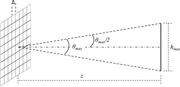
Figure 1. Schematic representation of maximum FOV and object size recorded by image sensor with pixel pitch ∆.
Download figure:
Standard image High-resolution imageEquation (3) may only be true for pixel around the central region of the sensor where (θmax/2) corresponds to (hmax/2). Hence, a generalized form of equation (3) for whole region of sensor can be obtained from ref [17] as:

Due to the limitations of sensor parameters, large object-to-sensor distance is required when it is used to record a large area of the test object. Thus, the dependence on pixel size restricts the compactness of the digital holographic system and aid to the bulkiness of the system. As the recording principle of digital holography is based on interference of two coherent beams, another limitation of digital holographic system is high sensitivity to environmental vibrations. With advancements in the technology of image sensors such as increase in density of pixels and smaller pixel pitch in the range of few microns, researchers have progressively worked on realizing compact digital holographic systems over the years.
Efforts have been made for longtime to develop compact and portable digital holographic systems [64–72]. Georges and Lemaire [65], reported a transportable holographic interferometer developed on the breadboard of size 80 cm × 30 cm × 20 cm and it weighed 15 kg. This system used copper doped BGO (Bi12GeO20) photorefractive crystals of the sillenite family to record the holograms for real-time interferometric analysis. This system achieved a large FOV of 55 cm × 37 cm at 1 m distance between object and optical head of the system using two objective lenses placed either side of the photorefractive crystals. The system was later improved [66] as a compact and portable holographic camera (cylinder of length 25 cm, diameter 8 cm, and weight 1 kg) that used the photorefractive crystals as the holographic recording medium along with imaging objectives and a CCD sensor. Here the developed holographic system was significantly compact and lightweight as compared to its previous breadboard version. This system achieved greater portability and similar performance as the breadboard prototype but was connected to a remote laser using an optical fiber. In an another significant development, Karl Stetson developed K100 electronic holography system [67] for automotive component analysis using holographic interferometry. The K100 comprised of a 90% beam splitter which direct 90% of the source light to illuminate the test surface and rest 10% light forms the reference beam. A beam expander in the illumination beam allowed variable beam size. A standard 6X TV zoom lens utilized to form an image of the object which was relayed to a TV camera connected to an interferometer module via a mirror, relay lens, and beam splitter. In further research, Michałkiewicz et al proposed digital holographic cameras [68] in two different configurations i.e., DH_SHAPE and DH_UVW for shape and three-dimensional displacement measurements of small region of interest (15 mm × 10 mm) on mechanical parts. Both configurations utilized a pigtailed laser source, placed outside the measurement head. The fiber optic module connected to the source contains a fiber coupler to create object and reference beams. An optical switch embedded in the module parted the object illumination beam to illuminate the object from multiple directions simultaneously. This system was compact and flexible enough to be used either hand-held or mounted on a machine and had remote reconstruction capability by using a liquid crystal on silicon (LCOS) SLM.
Maximizing the FOV is one of the primary factors while making compact digital holographic systems for inspection of large surfaces. In this direction, Mundt and Kreis investigated digital holographic system using concave lenses to record and reconstruct large-scale objects [69]. The optimized two-concave lens arrangement used in the recording setup significantly reduced the distance between the large object and the recording sensor. In principle, the concave lens creates a demagnified virtual image of the object. Thus, this combination of two concave lenses reduces the size of virtual image of the object so that it can be successfully perceived by the limited FOV of the recording sensor. Also, since these virtual images are created between object and sensor, it further reduces the recording distance. Using this lens arrangement in the digital holographic setup, an object of size 18 cm x 12 cm was recorded at the distance less than 22 cm (distance was 1.5 m in traditional digital holographic setup) between object and CCD sensor. Larger FOV in digital holographic systems can also be achieved by using longer wavelengths, which was explored by Georges et al through combination of holography and thermography in a single sensor through image-plane holography at thermal infrared wavelengths [70]. The developed system uses a long-wave infrared (LWIR) CO2 laser to realize digital holographic camera. The LWIR wavelength has the inherent advantage of a larger field of view and less sensitivity to vibrations compared to visible wavelengths. However, for LWIR wavelengths usually a CO2 laser is used which requires water cooling arrangements to stabilize temperature during operation to avoid mod hopping.
Employing multiple recording sensor in the digital holographic camera is another way of increasing the FOV. Zak et al reported an active holographic camera which included two CMOS image sensors to perceive two different views of test object and a LCOS SLM [71]. The arrangement of two image sensors improved the field of view and permitted recording of two double exposure holograms with different sensitivities. The LCOS SLM is used for phase shifting and as a wedge to create and direct two reference beams towards both the sensors. The camera was used to record two chess pieces of 15 mm height at 270 mm object-to-sensor distance and a stressed metal band of size 82 mm × 20 mm at 540 mm object-to-sensor distance. In recent times, incoherent digital holography has also become a research interest due to its flexibility in selecting light source other than coherent sources. Kim reported a full color self-interference incoherent digital holographic (CSIDH) scheme [73] in 2013. Here, Kim demonstrated 3D imaging in full color under natural light using digital holography. In 2019, Choi et al proposed a compact self-interference incoherent digital holographic camera for real time holographic recording and reconstruction [72]. This common path system is highly compact (typically same size as a human hand) and utilizes a geometrical phase optical component based on polymerized liquid crystal that acts as a lens by varying topological state of polarization. The system comprises a combination of polariser, geometrical phase lens, and polarized image sensor for wavefront division and parallel phase shifting to realise real time recording and reconstruction.
Certain important inferences can be drawn from these reported systems for developing a compact digital holographic system for out-of-lab applications such as larger FOV in compact DH system is necessary to inspect larger area in single recording and hence to make the measurement system faster. Several ways can be opted for this purpose in compact DH systems as reported above such as larger source wavelength, lens combinations/zoom lens, multiple recording sensors, etc. Among these, lenses are simpler and more economical solution to increase the FOV. The system should be easy to handle which can be achieved by making system compact and user friendly. Smaller sizes of system elements such as laser source, optical and opto-mechanical components benefit significantly in developing compact systems which now-a-days become possible with great advancements in fabrication and manufacturing technologies. Another primary factor for compact DH system is portability which is primarily challenged by ultra-sensitivity of interference fringes to environmental vibration, typically in the range of few nanometers. Some of the measures adopted to reduce the effect of environmental vibration may include use of pulsed laser sources, vibration damping mechanical mounts, and recording sensors with a fast exposure time in the range of microseconds.
Considering above requirements, one such compact and portable digital holographic camera (DHC) [74] was developed by the holography group of CSIR-CSIO. The primary vision behind this development was to explore the possibility of such DH systems in industrial environment for non-destructive testing (NDT) applications. The schematic representation of lens configuration employed in DHC and photograph of DHC mounted on commercial tripod are depicted in figures 2(a) and (b) respectively.
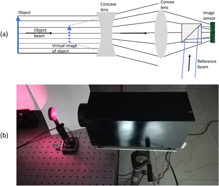
Figure 2. (a) Schematic representation of principle of recording holograms using combination of concave and convex lens arrangement employed in the DHC, and (b) Photograph of compact and portable DHC system mounted on tripod.
Download figure:
Standard image High-resolution imageThe optical source is a coherent laser diode (∼1 m coherence length) of small physical size (50 mm length, 10 mm diameter) with optimized power [75, 76] of 30 mW and central wavelength on longer side of visible light spectrum i.e., 660 nm was selected to get wider FOV in visible range. The optical components employed in the DHC include a microscope objective to expand the thin laser beam emitted from the laser diode, cube beam splitters to create illumination and reference beams and to combine object and reference beams, and lens combination to increase the FOV and simultaneously reduce sensitivity to environmental disturbance. As shown in the schematic in figure 2(a), the combination of concave and convex lens arrangement was designed for 100 mm long object to be placed at 150 mm from the front end of the DHC. Using the lens formula, the optimized focal lengths obtained are −50 mm for concave lens and 80 mm for the convex lens placed 100 mm apart from each other. Using this lens arrangement, the FOV of the DHC is increased by 192% compared to the traditional DH system without lenses for the recording sensor with pixel pitch 3.1 μm. The portable DHC can be mounted on a commercial tripod, as shown in figure 2(b), for onsite NDT.
Although use of two concave lenses can increase the FOV further as reported in [64], but for a portable DHC it may prove disadvantageous due to high vibration sensitivity of interference-based systems. The concave lens considerably reduces the light reaching the recording sensor by diverging the light in its output. So, the exposure time of the recording sensor has to increase to acquire sufficient light for hologram recording. One simple way to counter this problem is by introducing a convex lens after the concave lens which will collect the light after concave lens and converge it onto the recording sensor. Thus, the exposure time requirement of the sensor is decreased considerably due to increase in amount of light illuminating the sensor and hence the effect of environmental vibrations is also reduced during recording. Thus, this lens arrangement, shown in figure 2(a), utilized in developing the DHC not only increases the FOV but also reduces the effect of environmental vibration. However, this lens combination in DHC has lesser FOV as compared to two concave lens arrangement, but provides better stability against environmental vibration. A number of other optical configurations [34, 63, 77–82] based on Lloyd's mirror, Fresnel bi-mirror, Fresnel bi-prism, Wollaston prism, Rochon polarizer, wedge plate, gratings etc have been reported to make the system compact with enhanced FOV.
6. Applications of single-shot digital holography
In many applications the reconstructed complex amplitude of the recorded wavefront is suitable. Here the property of digital holography that it could provide direct digital access to individual amplitude and phase of the reconstructed wavefront is used. Since this information is available digitally, it can be independently processed using digital image processing techniques. This enabled DH to provide efficient solutions in imaging applications including holographic microscopy and holographic dynamic displays. Here we consider these two applications.
6.1. Digital holographic microscopy: a key to development of holographic instruments for diagnostics
Microscopy is one of the important applications of holography. Actually, invention of holography took place while working on microscopy only [2]. Now, digital holographic microscopy (DHM) is one of the leading microscopy technologies. DHM exploits the principle of numerical imaging, where complex amplitude extracted from the DH is used to create holographic images [8–11]. Here optical field of the magnified view of the sample is recorded into hologram by interference with a reference beam, as schematically shown in figure 3.
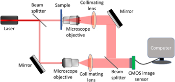
Figure 3. Schematic representation of optical arrangement of a typical DHM setup based on Mach–Zehnder interferometer.
Download figure:
Standard image High-resolution imageA DHM experimental setup generally consists of a light source, an interferometer with microscopic optical components, a digital image sensor, and a computer for storage and processing of the hologram. Commonly, a laser is used as light source for illumination with the sufficient coherence to generate interference. Most often, Mach–Zehnder or Michelson optical arrangements are considered as interferometers. Figure 3 shows a Mach–Zehnder based DHM arrangement where a thin beam from laser source is split into two parts by a beam splitter. One beam illuminates the sample. A microscope objective magnifies the illuminated region of the sample and after collimation, relays it to a digital CMOS image sensor. The other beam is expanded and collimated to form a reference beam, and superimposed with the object beam coming from the sample. This superimposition creates interference pattern which is recorded as digital hologram in the computer. The recorded digital hologram is numerically reconstructed allowing various controls over the imaging properties and instrumentation as well. Numerically, aberrations of the instrument can be taken care-off [61, 83–85]. The problem of short working distance now has been successfully resolved [86], with extended depth of field and autofocusing capabilities [57, 58]. DHM could be successfully implemented with existing capabilities of the digital image sensors and it suitably exploited most of the novel features offered by DH. DH has emerged as a popular phase imaging technique applicable to most objects of various optical properties such as transparent, semi-transparent and reflective objects, and new aspects are being added continuously to DHM with progress in software and hardware. The advantages of DH have been utilized for successful realization of compact lensless DHM configurations. One such configuration of lensless DHM on a chip is schematically shown in figure 4. The various aspects of lensless DHM and its applications in biomedical, air and water pollution monitoring are reviewed in reference [87].
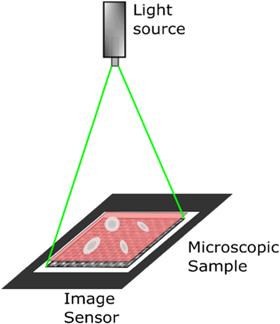
Figure 4. Schematic representation of Lensless DHM on a chip.
Download figure:
Standard image High-resolution imageIn such systems the sample is placed very close to image sensor (typically <1 mm apart) and the hologram is recorded after illuminating the sample with a partially coherent light. So, in contrast to traditional compound microscope, this arrangement does not require any imaging lens, hence reduces the bulkiness, cost, and complexity of the system. Further, different sample illumination schemes could be employed according to the requirements of intended application. Use of stochastic illumination has been demonstrated for imaging of specular reflecting objects [40] and super-resolution could be achieved using structured illumination [62, 88]. These illumination schemes could be extended to DHM and other holographic microscopy based schemes such as optical diffraction tomography (see figure 5), which involves reconstruction of 3D refractive index distribution of a phase object from its multiple 2D holograms acquired from different illumination angles [89].
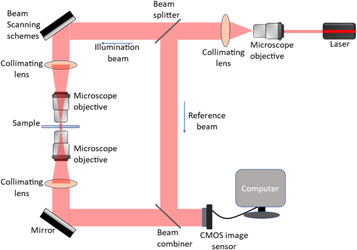
Figure 5. Schematic representation of a typical optical diffraction tomographic system.
Download figure:
Standard image High-resolution imageThe angle of illumination on the sample can be controlled by various techniques based on illumination scanning (e.g. using dual axis Galvano-mirror, or spatial light modulator, or digital micromirror device) and sample rotation (e.g. using rotation stage, or translation stage for axial scanning). Optical diffraction tomography based instruments can be widely utilized in biomedical sciences for measurement of 3D refractive index distribution of transparent/weakly scattering biological cells. Thus, DHM is one of the success story of DH and still an active research with great potential of scientific and commercial value. The field of DHM has matured and its principles, techniques and applications have been documented in detail in few of the books and review articles [7–11, 27–30, 90–93].
DH provide phase information over the depth of the phase object or of the surface variations only. To obtain depth resolved phase information inside the test sample the combination of DHM with phase contrast microscopy has resulted into improvement in tomographic imaging and now this technique is also known as holographic tomography [94, 95]. It allows simultaneous measurement of depth information with quantitative information about thickness and refractive index of the media. Also DHM has been successfully combined with other microscopic techniques for multi-modal imaging applications [96–100], such as bright field, dark field, phase contrast, fluorescence imaging, Raman spectroscopy etc. The multimodal imaging systems enable simultaneous measurement of various parameters of the test sample in a compact and efficient manner. These systems are very suitable for real-time study of behaviour of living biological objects such as cells, tissues, bacteria, viruses etc without mandating staining and thus are suitable for development of DH instruments for clinical diagnostics. Digital holographic endoscopy [101, 102] also use this concept for imaging internal body parts including deep brain as well as inaccessible industrial components by imaging through thin optical fibers. A number of digital holographic microscopes have been designed, developed and successfully commercialized [103–106]. Some recent developments include, dual wavelength Fresnel biprism-based configuration [107], and Blu-Ray pickup-based configuration [108] which are applied to different biomedicine and industrial applications [33, 109–111].
6.2. Holographic dynamic displays
Holographic principle has always attracted the attention of researchers as well as general public for its ability to create realistic 3D images without mandating additional devices such as glasses to create the 3D images. Holographic displays provide accurate 3D depth cues and thus could be the leading technology for many current and future applications including entertainment, healthcare, telepresence, education, training, engineering inspection and metrology etc through AR/VR/MR displays [8, 112–116].
In conventional holographic displays, emulsion based hologram recording materials such as silver halide, photopolymer, photorefractive etc are used to record the holograms optically [8, 117]. These materials have very high spatial resolution and thus are suitable for recording holograms of large size objects. The main limitation of conventional holographic displays is that they are static or slow in nature and thus are not suitable to record holographic videos.
Digital holography on the other hand uses digital image sensors such as CCD and CMOS, which can record hologram at video rate and numerical reconstruction algorithms provide almost real-time reconstruction from these digital holograms. These reconstructed holographic images could be displayed on 3D image forming devices such as SLM or DMD. Here, instead of reconstructed holographic images the complex amplitude or amplitude or phase of the recorded wavefronts are numerically calculated and displayed on 3D display devices [118–121]. Upon illumination with reconstruction optical beam the reconstructed holographic 3D images are obtained. Thus, DH can be used for generating dynamic holographic displays or holographic videos [67]. This technique may ultimately pave way for the development of holographic television [122]. Other techniques such as computer holography may also be useful for the improved experience [123–126]. Here main limitation comes from the low spatial resolution and small SBP of the digital image sensors and the digital image display devices [127]. In order to overcome the issues related with small FOV and low SBP of digital holographic imaging and display devices a number of configurations have been reported in the literature [112–127]. Here, few image sensors and same number of digital display devices could be arranged in suitable configurations [121, 122]. AV/VR displays are successfully commercialized [114] and other dynamic holographic displays [126] are being actively pursued for development and commercialization.
6.3. Holography for environment and oceanic studies
Recording of particles distributed in 3D space is one of the first and important applications of holography. Study of distribution and tracking of particles is required in many applications [12–15, 128, 129] including clinical studies, design of fuel injectors, sprays, bubble chambers, industrial combustion of coal, fluid flow studies, ballistic studies, particle-shock wave interactions, aerosol studies etc 3D dynamics of the particles is studied by recording their video in action which also enable study of large volume of particles distributed over the video recording range. These studies provide opportunity to improve nozzles, efficient energy utilization, to control environmental pollution, improved designs of ballistics, oceanic plankton distribution, cloud formation, weather forecasting etc. Digital holography is finding increased role in particle studies as it can provide positional 3D information about a larger number of particles of different sizes compared to other optical techniques [128, 129]. Here in-line digital holography is emerging as a leading research and application area. In holographic particles studies the movement of particles in the volume is tracked. It is also applied for measurement of microfluidic shear rheology and wall slip of viscoelastic fluids, wherein the fluid flow is seeded with microparticles and their movement in the fluid is tracked by holographically locating their centroids.
Digital holography is also finding applications in environmental [12–15], clouds [130–133] as well as for oceanic studies [134, 135] as it can provide correlations of particles through the position and shape retaining property, which is not available with other techniques. Micro scale study of composition, evolution and formation of clouds is important as these greatly influence weather of a particular location. Particle number, shape, size, and refractive index are important parameters to be quantitatively studied in a given volume of cloud. In in-line DH the object and reference beams travel along the same path. These are single beam systems and thus are not much affected by the system and environmental vibrations as both the beam are equally affected. Here a single beam is used to illuminate the sample containing tiny particles. Light scattered from the particles form the object beam while unscattered light directly reaching to the image sensor serves the purpose of reference beam. The size of particles is small enough so that even a small physical distance between the particle and the sensor satisfies the far field/ Fraunhofer diffraction condition and thus conjugate image of the particle becomes out of focus and therefore does not create problems, as is observed in the case of in-line holographic imaging of regular objects [1, 134]. In DH particle image velocimetry (PIV), where microparticles are seeded into the flow field and holographic reconstruction provides detailed and precision information of the seeded particles is useful for flow field studies such as measurement of microfluidic shear rheology [112, 113].
7. Interferometric applications of digital holography
7.1. Principle of holographic interferometry
As described above holographic technique conveniently reconstructs complex amplitude of the recorded object. If two such wavefronts of the same object belonging to its two different physical states are optically or digitally compared the interference fringes corresponding to change in states are formed. If at least one of the interfering wavefront is holographically recorded and reconstructed, then the process is known as holographic interferometry (HI) [16, 17]. These interference fringes could be easily used for qualitative as well as quantitative analysis of the forces causing the object deformations. Consider wavefront  corresponding to unstressed state of the object is:

After external loading, wavefront corresponding to stressed state of the object become, 

Where Ai (x, y, z) and φi (x, y, z) represent amplitude and phase distributions respectively of beams I = 1, 2. The phase difference Δφ(x, y, z) = φ1(x, y, z)- φ2(x, y, z), between the two states of the object wavefront gives information about the distortion encountered by the test object under study. This phase difference is encoded in the cosine interference fringes, which can be further processed to obtain the desired parameter like displacement, refractive index, density, etc.
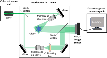
In optical holography these two wavefronts are reconstructed optically using different holographic interferometric schemes such as double exposure, real-time or time average HI [16]. In DH wavefronts are numerically reconstructed and digitally compared [17]. DH provides direct access (in digital form) to the complex amplitude of the reconstructed wavefront, from which either amplitude information or phase information can be directly obtained and processed. Numerical subtraction of wavefronts corresponding to different states of the object provides digital interference fringes, which are further processed by using interferogram analysis techniques [136] to obtain the desired parameter of the test object. HI directly measures intensity and phase of the wavefronts scattered by the test object. Further digital processing of these fringes provides information about displacements, deformations, strain, residual stress, defects, delaminations, 3D shape etc. A typical DHI system consists of a laser source, an interferometric scheme, an optical detector/ sensor array, and a data storage and processing unit, as schematically shown in figure 6.
The holography and interferometry have same principle of recording the amplitude and phase modulation of object beam with the reference beam in terms of intensity pattern. During processing holography recreate propagating wavefront that can be numerically focused in the image plane while interferometry provides integrated information of the path travelled by the beam upto the recording plane. A precisely focused image is desirable in many alignment and measurement industrial applications, which increases cost of the equipment and alignment time at each component. Thus, holographic autofocus procedures [57, 58] are beneficial here.
Incorporation of digital techniques in holography led to the development of TV holography for almost real-time recording using video camera and numerical reconstruction of holograms [50]. This was an extension of the speckle interferometry [42] and thus is also known as 'electronic speckle pattern interferometry (ESPI).' Early TV/ESPI techniques used analogue methods to process the video, which requires bulky and expensive systems. Commercial availability of cost-effective personal computers, digital image sensors and development of fast numerical computation, fringe analysis and image processing algorithms and softwares accelerated work on digital holography. Availability of digital sensors with sufficient pixel density to resolve the holographic fringes made it possible to record holograms other than image plane holograms like Fresnel hologram, resulting in digital holographic interferometry to provide direct phase information instead of first derivative of the phase obtainable in shearing interferometry. In ESPI, an imaging system is required to image the speckles on the image sensor while in HI different other optical configurations including lensless imaging are possible. In holographic schemes, numerical propagation algorithms are used to reconstruct the holographic image. Numerical manipulation of reconstructed wavefront also allows to shift the focal plane for producing focused image beyond the geometrical depth of field [57, 86]. Thus, developments in DH and DHI were fuelled by the wide availability of personal computers with enhanced computation power, digital image sensors with increased pixel density, and the algorithms for accelerated numerical reconstruction and processing of interferometric fringes with implementation of arithmetic formulas such as addition, subtraction, differentiation, integration allowing digitally aberration compensation [61, 83, 84]. These allow real-time holographic study of various phenomena including vibration analysis, fluid mechanics, solid mechanics and NDT among others.
Figure 6. Schematic representation of an off-axis DH system to perform DHI.
Download figure:
Standard image High-resolution image
Image plane holography, where focused image is recorded on the sensor, is used to study topography of the object. The focusing error generally encountered with the conventional interferometers can be easily solved in holographic systems through the process of numerical refocusing. A number of autofocus algorithms and techniques [57, 58] have been developed to numerically focus the propagated wavefronts in real-time. Reconstructed information provides surface topography phase wrapped in the range between -π and π. Thus, unambiguous measurement range is limited to half the size of the wavelength of light used. Therefore, if surface height variations are larger than the wavelength of light used than phase unwrapping process does not work well and thus could not provide accurate results [136]. In order to solve this issue, two wavelength interferometry [137, 138] is used where holograms are recorded and reconstructed at two slightly different wavelengths so that effective synthetic wavelength becomes larger than the step height and phase unwrapping is done successfully. Thus, dual wavelength holography can be used for obtaining depth information of deep holes, steep surfaces, larger step heights or larger defects, displacements/distortions etc. Using dual wavelength scheme the measurable range can be extended but at reduced resolution. Multiple wavelengths can be used to generate several synthetic wavelengths by recording DH at various wavelengths. Cascading of reconstructed phase maps can be used for compensating the phase noise of larger synthetic wavelengths with smaller synthetic wavelengths [139, 140]. Here measurement range is determined by the largest synthetic wavelength while measurement accuracy is limited by the smallest synthetic wavelength. This enabled DHI applicable to a number of scientific and industrial applications.
7.2. Holography in manufacturing
DHI methods can be easily applied for defect detection, structural integrity and health monitoring to various items, product and systems including delicate items of art work, paintings, furniture, statues, icons etc [16–20, 22–24]. Thus, these methods alongwith other optical techniques have high potential for industrial applications including inspection, quality control, measurements and NDT. Various industries such as aerospace, manufacturing, automotive, energy, cultural heritage could be benefited from holographic NDT methods including HI, ESPI, time-average holography, TV holography and /or DSPI. A number of industrial applications such as testing of macro systems including turbine blades, tires, composite materials, photovoltaic solar panels, automobile components, engine vibrations and electronic circuits, to microsystems such as MEMS, MOEMS, and NEMS have been successfully demonstrated either in laboratory or directly in the industrial environment [16–20, 22–24, 27–30]. DHI methods have been used for dimensional metrology, surface topography, roughness and form measurements [18–20, 27–30, 137–142]. Application of these methods is also demonstrated for machine tools testing [47, 48], photo-polymerization process [143], monitoring of fibers drawn using electrospinning process [144], as potential candidate for onsite studies. With technological advances and development of new manufacturing processes such as additive manufacturing and rapid prototyping, improved quality control and precision measurement methods are required. Due to precision, accuracy and speed, optical methods are suitable for these emerging technologies. Interferometry based methods which can measure even slightest deviation or defect in the manufactured components through quantitative phase studies are very promising for inspection of the manufactured components. DH instruments are now a days emerging as the leading technologies for deployment in industry to improve the quality of manufactured products through distinctive features of this technology such as 3D inspection, speed, accuracy, numerical propagation and focusing, non-contact, non-invasive, applicability to objects of a wide range of optical, mechanical, chemical, physical, and electrical properties. These inherent characteristics of DH make it powerful tool for manufacturing industry for real-time in situ monitoring of the fabrication process. Demand for development of more compact and industrial grade DHI systems is continuously on rise to precisely test and quality control of mass produced components in many industries such as automobile, avionics, medical, semiconductor, composite materials, photovoltaic solar panels etc. A number of review articles and books dedicated to HI, HNDT etc have been published [16–20, 22–24, 27–29, 50–52, 90–94, 145] .
Availability of high speed camera with high resolution and development of fast algorithms and computational platforms with increased performance further increased deployablity of DH systems for industrial applications. Now advanced computational techniques such as deep learning, neural networks with capabilities of autofocusing, phase unwrapping, aberration compensation etc have further increased speed and accuracy of numerical reconstruction of digital holograms making DH more relevant for scientific and industrial applications. Standards are also being developed for few of the requirements such as ASTM E2581-14 for industrial inspection using shearography [146, 147]. A number of instruments and systems based on holography or shearography have been developed and commercialized [148–157].
8. Future perspectives
Digital holography has made phenomenal progress in terms of system design, and development by taking advantages of compact lasers, digital detectors, algorithms, and increased computation capabilities of personal computers. It has been used already in few of the industrial and scientific applications. One of the success stories is DHM. Others include systems for environmental, oceanic, industrial and scientific studies.
A lot of work is further required in terms of development of compact, rigid and field deployable DH instruments with increased field of view. The measurement range and vibrations are still issues that need to be addressed efficiently. Though few systems with long wavelength have been described to reduce the effect of ambient vibrations but more detailed analysis is required in terms of their performance in different industrial environments.
Characterization of system performance and their standardization is required for industrial acceptance of these comparatively new systems. One of the challenges is non-availability of standards applicable for holographic instruments. It is the responsibility of global digital holography community to collectively develop standards for the DH systems and instruments to make these more reliable and robust for their wider acceptance in scientific, clinical and industrial applications.
Further, more research and innovations are required to develop novel DH systems for different emerging and unexplored areas of research and development such as space, astronomy, cosmology, stellar, communication, remote metrology, telepresence, displays and healthcare applications. An example of such system is the SHIVA program of NASA [44]. Integration of emerging technologies such deep learning, internet of things, cloud computing, robotics, AR/VR/MR/XR/metaverse etc with DH systems could make it possible to develop DH systems for these until unexplored applications.
Data availability statement
All data that support the findings of this study are included within the article (and any supplementary files).
Funding
The research work is financially supported by the CSIR, India under project number MLP-2014.