
Abstract
This paper presents a novel MEMS tunable resonator that draws inspiration from the folded beam structure in its comb drive resonator design. Conventional electrostatic comb-drive resonators commonly employ folded-beam suspensions to achieve linearity and reduce system stiffness. The proposed design incorporates eight zigzag-shaped meander springs to support the comb finger structure, featuring two central anchors. The objective of this design is to introduce zigzag-shaped nested-folded beam suspensions to the comb parts, thereby reducing the tuning voltage and sensor size. The governing equations are provided to calculate the support springs' stiffness, and a comparative analysis is conducted to evaluate the stiffness of the proposed design against other parameters. The mathematical analysis demonstrates that Zigzag Nested-Folded beams result in a decreased resonance frequency and a softened electrostatic spring under applied DC voltage. The integration of zigzag-shaped nested-folded beam flexures enables MEMS resonator devices to exhibit reduced stiffness, leading to a lower pull-in voltage. The resonator design and simulation are performed using Intellisuite and SolidWorks software. Results indicate that the resonant frequency of the proposed tunable comb-drive resonator, equipped with 26 finger pairs and a movable part displacement of 21 μm, is reduced by 66% from the original frequency of 2.420 kHz when a tuning voltage of 59 V is applied. Simultaneously, the corresponding effective stiffness decreases by 66% from the initial value of 0.72 N m−1. This compact resonator occupies an area of approximately 1.058×278 (μm)2, demonstrating a smaller size compared to previous works.
Export citation and abstract BibTeX RIS
1. . Introduction
Microelectromechanical resonators are used for building complete sensor systems including the detection of chemical [1] and biological substances [2], and energy harvesting [3], to name only a few. A resonator is a device or structure that will resonate at particular frequencies, called resonant frequencies, with a higher amplitude compared to other frequencies. Generally, these devices are operated with thermal, piezoelectric, or electrostatic forces. Electrostatic actuation is the most common type of electromechanical energy conversion scheme in micromechanical systems due to its ease of fabrication, nearly zero power consumption, and small electrode size.
Parallel-plate or gap-closing actuators are the most popular type of electrostatic actuators used in micro-electro-mechanical systems (MEMS). Commonly, parallel plate actuators, as the name suggests, are composed of two conductive plates, one movable and one fixed, with a gap between them. Electrostatic comb drives are desired for numerous applications as they are constructed from easily obtainable materials and can produce large deflections at lower voltages with steady functions. Many MEMS resonators utilize 'comb drives' for actuation and sensing, which consist of one stationary and one movable set of interdigitated comb fingers that are operated by applying an electrostatic field between them. One of the comb support structures is firmly secured and does not fluctuate. A spring or folded beam that is free to move and supply the restoring force to equalize the electrostatic force is connected to the second comb support structure. Applying a potential difference between the two sets of combs generates an electrostatic force, making them move in the direction of one another. The comb is only able to move in the direction of comb meshing, which maintains the space between the two fixed plates and locates the moveable plate between them. A variety of implementations have been executed in accelerometers, microgrippers [4], resonators [5], filters [6], generic force actuators [7], two-dimensional microstagers [8], and micromirrors [9]. The tunable resonator combs can be classified into three sections: the driving, sensing, and tuning sections. The tuning component of a tunable resonator is essential, as the resonant frequency of the resonator can be regulated by the implementation of a DC voltage, while the sensing element identifies a variation in capacitance when voltage is applied to the driving part. Several strategies have been utilized for modifying the resonant frequency of a Microelectromechanical actuator. In this study, adding an electrostatic spring constant to the mechanical stiffness of the configuration technique has been used.
A triangular comb with uniform varied finger lengths to provide a linear electrostatic force was demonstrated in [10]. Inspired by this method, a triangular comb with non-uniform varied finger lengths was presented in [11], which improved the resonant frequency tuning range. Additionally, [12] showed how different comb finger shapes can lead to either stiffness softening or stiffness stiffening. Additionally, rather than adapting the stiffness of the device by changing the shape of the fingers in the flat directions, the height of the fingers could be adjusted along the length of the finger [13].
Microbeams are essential components in a majority of micro-electromechanical systems (MEMS). The shape and mechanical properties of microbeams dictate their functional features.
These components act as the basis for a great variety of devices including resonators, resonant sensors, actuators, filters, atomic force microscope probes, and RF switches. They function as a spring element with other microstructures and MEMS components, such as comb-drive actuators. The primary resonance frequency of a comb-drive resonator is determined by microbeam stiffness. Enhancing the stability of a comb structure can be possible by employing beams created in the form of folded flexure [14], a tilted folded beam suspension [15], or a nested folded beam suspension [16].
This research proposes a MEMS comb tunable resonator featuring a triangular comb with non-uniform finger lengths and zigzag nested-folded beam suspensions. The aim is to expand the tuning resonant frequency range while minimizing the required tuning voltage. Zigzag meanders are employed to decrease the tuning voltage, primary resonance frequency, and overall device dimensions. The movable element of the proposed actuator is supported by eight flexible beam suspensions on each side. Additionally, a comparison of the actuator's parameters with those of previous works is presented in table 2. Section 2 provides a detailed description of the designed structure, along with mechanical and electrostatic analyses. The results indicate a primary resonant frequency of approximately 2420 Hz, which can be reduced to 820 Hz when a tuning voltage of approximately 59 V is applied to the tuning part.
1.1. Design and modeling of the MEMS resonator
Subsequent sections will introduce both the structure of a conventional MEMS tunable comb resonator and the proposed resonator. Furthermore, section 2.2.1 will investigate the spring constant and effective mass of the device to achieve the desired primary resonance frequency of the actuator.
1.2. Common structure of MEMS tunable comb resonator
Electrostatic actuators are based on the fundamental principle that two plates of opposite charge will attract each other. They are most common in micromechanical systems as they are relatively straightforward to fabricate. Comb-drive structures are particularly popular with surface-micromachined devices. The structure of this type of actuator commonly consists of many interdigitated fingers, where one of the combs is movable and the other one is fixed. When a voltage is applied, an attractive force is produced between the fingers, which move toward each other. The increase in capacitance is proportional to the number of fingers; so to generate large forces, a large number of fingers are needed. Consider a simple comb drive having a gap separation, g, with N electrodes, the capacitance of this configuration with no fringing fields is approximate [17]:

where x0 , ε, and t are the finger overlap, the absolute permittivity of air and the device thickness, respectively.
1.3. Description of the proposed resonator structure
Figure 1 illustrates the resonator, comprising three components: a driving part that generates a driving force, a sensing part for detecting capacitance changes during vibration, and a tuning part that alters the resonant frequency when a tuning voltage (Vt) is applied. In this study, Zigzag Flexures were incorporated into the nested folded beam suspensions to decrease mechanical stiffness and reduce the required tuning voltage. Additionally, the resonant frequency tuning range was significantly expanded by employing a triangular comb finger with non-uniform finger lengths in the tuning part. The device utilized polysilicon with a 30 μm thickness as the structural material, situated on a silicon wafer. The tuning part comprised two sets of interdigitated fingers, each comprising 26 fingers.

Figure 1. Schematic illustration showing three parts of the proposed resonator: Sensing part, Tuning part, and Driving part.
Download figure:
Standard image High-resolution image
Figure 2. Zigzag-shaped meander used in the resonator is shown in figure 1.
Download figure:
Standard image High-resolution image1.3.1. Mathematical analysis
Table 1 summarizes the detailed characteristics of the proposed tunable comb-drive actuator and also serpentine nested folded beam suspension. The mechanical properties of resonators depend on their shape, and type of materials. In this section, the mechanical analysis of the proposed resonator is presented. Determining the stiffness properties of microstructures is vital to model their behavior and analyzing their motion. In the small displacement regime, the spring constant of any flexible beam for a concentrated force in the longitudinal direction can be expressed as:

where E, t, wb , L represents Young's modulus, the structure thickness, the beam width, and the beam length respectively.
Table 1. Parameters associated with proposed resonator shown in figure 2.
| Symbol | Description | Value |
|---|---|---|
| LMb1 | Beam Length with Serpentine Meanders | 348 μm |
| Ls1 | First Block of Serpentine Length | 52 μm |
| Ls2 | Second Block of Serpentine Length | 8 μm |
| Ls3 | Third Block of Serpentine Length | 40 μm |
| Wb | Beam Width | 2 μm |
| h | Device Thickness | 30 μm |
| — | Device Material | Polisilicon |
| N | Number of finger pairs in every comb set | 26 |
| — | The Smallest Finger Length in Downward Tuning Part | 4 μm |
| — | The Largest Finger Length in Downward Tuning Part | 40 μm |
| g | The Minimum spacing amount between fixed and movable fingers | 1.5 μm |
| — | The Difference between Fingers Length of Downward Tuning Part | Non-Uniform |
| A0 | Triangular Comb Height | 108 μm |
| B | Triangular Comb Base | 36 μm |
| b | Initial Finger Overlap | 18 μm |
| Km | Mechanical Stiffness | 0.7251 N m−1 |
| Meff | Effective Movable Structure Mass | 3.0751e-09 Kg |
As shown in figures 2 and 3, each beam is made of nine blocks connected in a series configuration. To access the stiffness of the proposed structure, the methods of combining stiffnesses in series or parallel are used. Consequently, the inverse stiffness of each flexible beam in this layout can be obtained by the summation of the inverse of each block stiffness. Based on this, for every flexible beam of the proposed resonator, the mechanical spring constant can be expressed as follows [18]:

where S1 , S2 , and S3 are the first, second, and third block of zigzag meanders respectively; Mb1 is Beam with Serpentine Meanders. Two spring constants of Kb1 and Kb2 share the identical end deflection, they are parallel and form a spring constant K12 as follows:

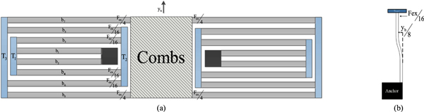
Figure 3. Geometrical details of the device. a) Top view of the tunable comb resonator with eight beam on each side. b) The first beam (b1 ) displacement under electrostatic force (Fex /16).
Download figure:
Standard image High-resolution imageIn the same way, two springs of stiffness coefficients Kb3 and Kb4 are parallel to each other and create a spring constant K34 , two flexible beams with stiffness constant of Kb5 and Kb6 constitute a parallel spring K56 , and two springs of Kb7 and Kb8 form a parallel spring K78 as follows:


The stiffness coefficient of K12 is connected in series with K34 and form KP1 :

As well as the stiffness coefficient of KP1 is coupled in series configuration with K56 :

Similarly, after calculating KP2, as well as using equation (7), the stiffness coefficient of the left side of the proposed device can be written as follows:

The sets of interdigitated combs are attached to the two sets of springs, thus, the value of Km is twice the value of the spring constant of one set, KL :

where KR represents the right side mechanical spring constant of the nested-folded beam. Substituting the parameters of table 1 and solving for Km from equation (11) gives Km = 0.7251 N m−1.
To calculate the primary resonance frequency of the resonator, in addition to the spring constant, the mass of the device's movable part has to be obtained. By applying Rayleigh's energy method, the maximum amount of kinetic energy will be obtained at the maximum velocity of the structure and is given by [19]:

where M(comb), M(truss), M(Beam), V(comb), V(truss), and V(Beam) are the mass of the comb, the mass of the truss, the mass of the beam, the velocity of the comb, the velocity of the horizontal trusses, and the velocity of the beam, respectively. Consider the design shown in figure 3, the ratio between the velocity of the horizontal trusses (T1, T2, T3) and the sets of interdigitated combs can be written as follow:


where ω and yb , are angular velocity and the longitudinal displacement of each segment, respectively. So the kinetic energy for the set of combs and the three horizontal trusses are:


As shown in figure 3, the velocity profile for each flexible beam is [19]:


The kinetic energy KE of each spring is written in the form of:


The kinetic energy KE of the Nested-Folded beams is calculated by summing the kinetic energy of each individual flexible beam:

By setting the maximum kinetic energy equal to the total potential energy of the system, yields:

Therefore, the total primary frequency of the system will be given by:

Referring to table 1 and the mechanical stiffness of the device Km from equation (11), the primary resonance frequency of the device will be equal to fr = 2.444 kHz.
Consider figure 1, the total capacitance equation, is given below [10]:

where A0 is the triangular comb height; P is the pitch of the tuning comb fingers; b is the initial finger overlap; B is the triangular comb base. For this case, the electrostatic force acting on the movable part of the actuator is obtained by differentiating the electrostatic energy to the displacement, and takes the following form:

The electrostatic spring softening can be utilized to soften or tune the effective stiffness value of the device electrostatically or the resulting natural frequency of a design. Hence, the electrostatic spring of the resonator is obtained by taking a displacement derivative of equation (21), which yields:

The amounts of electrostatic force and stiffness rely on the surface area, the little gap width, and the applied actuation voltage Vt , as shown in equation (22). Therefore, as it is obvious from the above expression, it can be found that by using the triangular comb with non-uniform finger length, the electrostatic spring constant will considerably rise. Besides, the electrostatic spring effect 'softens' the system by lowering the effective spring constant of the device:

Substituting equation (23) into equation (19), the resonant frequency of the tunable comb resonator can be obtained as follows:

By incorporating equations (22) and (23) into equation (24), the following result can be obtained:

From equation (25), the resonant frequency can be tuned by applying the tuning voltage of Vt , to the tuning part, so the resonant frequency can be dropped, by increasing the tuning voltage Vt .
Furthermore, an important characteristic of the resonator is its frequency response. When the resonator is excited with a specific frequency (φ), it exhibits a remarkable property of responding to the excitation with the same frequency (ωn). This frequency response behavior demonstrates the resonator's ability to effectively resonate and vibrate at its natural frequency, allowing for precise frequency tuning and control in various applications.
Hence, the dynamic displacement of the movable part of the resonator can be determined using the following equation:

It is worth saying that when a comb-drive resonator is in equilibrium, the electrostatic stiffness (Kex ) is balanced by mechanical stiffness (Km ). Consequently, the maximum amount of tuning voltage that can be applied to the structure can be calculated by setting the electrostatic spring constant equation (22) equal to mechanical stiffness equation (11) as below:

Referring to table 1 and equation (27) the pull-in voltage of the proposed device is equal to 57.5 V.
1.4. Effect of zigzag shaped meander beams on resonator parameters
In this study, Zigzag flexures were incorporated at various positions within nested-folded beams, and their resonance frequencies were compared (figure 4). Section 3 will present the obtained results. Interestingly, it was observed that the resonance frequencies of these configurations were remarkably similar. However, when the zigzag meanders were positioned in the middle of each flexible beam, the restoring torque reached its minimum value, causing the device's resonance frequency to increase and reach approximately 3234 Hz. Consequently, through a comparison of the four folded beam configurations depicted in figure 4, the nested-folded beams design (figure 4(a)) emerged as the most optimal solution.

Figure 4. Zigzag meanders, in different locations of the nested-folded beams. (a) at the beginning and end of any flexible beam. (b) In the middle of each beam. (c) at the beginning of the beams. (d) at the end of every beam.
Download figure:
Standard image High-resolution image2. Result and discussion
The simulation results developed to verify the theoretical findings are discussed in this section. Figure 5 shows the maximum displacement of the resonator using IntelliSuite software.
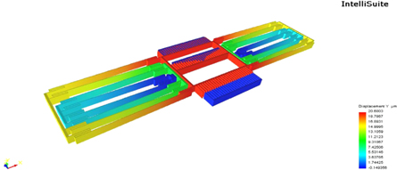
Figure 5. Displacement profile versus applied tuning voltage of the resonator.
Download figure:
Standard image High-resolution imageAs mentioned earlier, by placing the zigzag meanders in the middle of each flexible beam, the mechanical stiffness of the device would be increased. Hence, figure 6 shows that regarding the zigzag meanders in the middle of the flexible beams would increase the primary resonance frequency of the tunable resonator. Therefore, the optimized position for putting the zigzag meanders is at the end of every flexible beam where the relative amount of torque gets its greatest value.
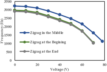
Figure 6. Comparison between resonant frequency versus tuning voltage of resonators in figure 4.
Download figure:
Standard image High-resolution imageFigure 7 shows simulated frequency response curve results for all resonators are shown in figure 4. This figure demonstrates, the highest primary resonance frequency is reached by using zigzag meanders in the middle of each beam which depends directly on the mechanical stiffness. Subsequently, according to equation (3), by increasing the third block length of zigzag meanders, the mechanical stiffness of the device would decline. The frequency response curves in figure 8, reveal that as the length of the third block grows from 10 μm to 40 μm, the primary resonance frequency of the resonator falls from 2948 Hz to 2420 Hz. Afterward, both electrostatic and effective stiffness curves of the proposed design versus tuning voltage using equations (22) and (23) are shown in figure 9. It is clear that adding zigzag meanders with 40um length to the nested-folded beam suspensions and integrating them by triangular comb with non-uniform varied finger lengths is an effective way to provide the displacement-dependent electrostatic spring constant needed to adjust resonance frequency and ease large displacement motion. In figure10, we can also see the effective stiffness Keff to the mechanical spring constant Km ratio against tuning voltage. It can be seen that the resonator with a zigzag meander length of 40 μm reaches its lowest resonance frequency with lower applied voltage as compared to other designs. The relationship between the displacement and the corresponding applied tuning voltage has been plotted in both lateral and longitudinal directions and is shown in figure 11 and figure 12. It is explicitly shown in figure 11 and figure 12 that a comb drive actuator with a 40 μm zigzag meanders length can achieve its maximum displacement in both x and y directions by the lower tuning voltage than zigzag meanders with a smaller length.
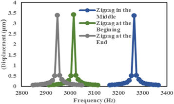
Figure 7. Frequency response diagram of the comb resonators proposed in this research with various zigzag nested-folded beam.
Download figure:
Standard image High-resolution image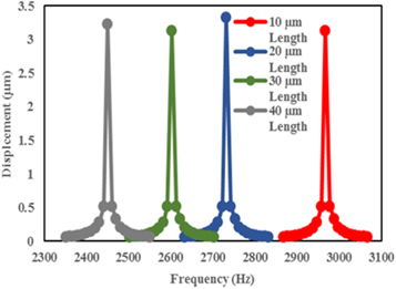
Figure 8. Frequency response curves of the proposed resonator associated with increasing the length of the zigzag meanders from 10 μm to 40 μm.
Download figure:
Standard image High-resolution image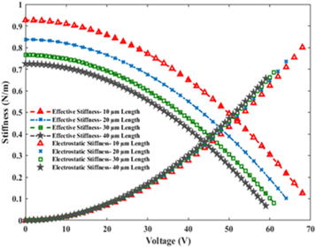
Figure 9. Effective and Electrostatic constants of the tunable comb resonator with different zigzag meanders length versus applied tuning voltage.
Download figure:
Standard image High-resolution image
Figure 10. Effective stiffness to mechanical stiffness ratio against applied tuning voltage for the resonator with different zigzag meanders length.
Download figure:
Standard image High-resolution image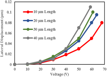
Figure 11. A lateral displacement comparison among four tunable comb resonators with an identical set of interdigitated combs and various zigzag meanders length.
Download figure:
Standard image High-resolution image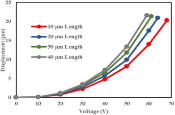
Figure 12. The maximum displacement comparison among the resonator with different zigzag meanders length.
Download figure:
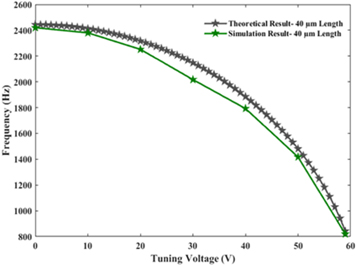
Standard image High-resolution imageConsequently, by applying a voltage of 59 V to the tuning part and 5 V to the driving part, the movable part of the device will move approximately 21 μm. Moreover, figure 13 depicted a comparison between the theoretical results acquired using equation (24) and the simulation results (using IntelliSuite software) of the proposed comb tunable resonator. It can be seen that the theoretical and simulation results are in good agreement. The resonance frequency can be changed from 2420 Hz to 820 Hz by applying the tuning voltage up to 59 V. Therefore, simulation and theoretical results illustrated that the resonant frequency tuning range of the presented comb resonator is approximately 66%.
Figure 13. Theoretical and simulation results of the proposed tunable comb resonator of figure 1.
Download figure:
Standard image High-resolution image
In short, the proposed resonator has eight flexible beams on each side with zigzag meanders at the end of them in which the length of each beam is around 348 μm. As a result, the corresponding effective stiffness has dropped 66% from the primary value of 0.72 N m−1, by applying the tuning voltage of 59 V. Also, by adding zigzag meanders at the end of every flexible beam the resonator's dimension has been reduced to 1058×278×30 (μm)3. Finally, a comparison between the parameters of this actuator and previous works has been presented in table 2.
Table 2. Comparison between tunable MEMS comb resonators presented in previous papers and this paper.
| Electrostatic mechanism | Primary resonant frequency (KHz) | Tuned resonant frequency (KHz) | Applied tuning voltage (V) | Tuning range | Resonator dimensions (mm2) | References |
|---|---|---|---|---|---|---|
| 21 | 19.383 | 46.1 | 7.7% | 0.065 × 0.065 | [20] | |
| 4.2 | 5.3 | 90 | 20% | — | [12] | |
| 4.1 | 3.3 | 80 | 20% | — | [21] | |
| 3.578 | 1.549 | 80 | 57% | 1.12 × 0.53 | [11] | |
| 4.84 | 4.51 | 25 | 6.8% | — | [22] | |
| 1.598 | 1.508 | 80 | 5.6% | — | [13] | |
| 21 | 23 | 72 | 8.6% | 0.73 × 0.5 | [20] | |
| 2.420 | 0.820 | 59 | 66% | 1.058 × 0.278 | In This paper | |
| Mechanical Tuning | 10.8 | 21.4 | 240 | 50% | — | [23] |
| 0.227 | 0.124 | 60 | 53% | — | [24] |
3. Conclusion
In conclusion, this study introduces a novel design of a tunable resonator that combines nested folded beams with zigzag meanders. By employing this technique, significant improvements have been achieved in terms of the applied tuning voltage and the resonator's dimensions, surpassing previous works. Thorough mechanical and electrostatic analyses were conducted, revealing a firm agreement between simulation and theoretical results. The proposed resonator demonstrates an impressive reduction in resonant frequency, dropping from 2420 Hz to 820 Hz by varying the tuning voltage from 0 to 59 V. The effective stiffness, a key parameter, exhibited a primary value of 0.72 N m−1, which significantly decreased to 0.1537 N m−1 with the tuning voltage raised to 59 V. Furthermore, a comparative analysis was performed between the resonator presented in this work and previous studies. The results highlight a remarkable expansion in the tuning range of the resonance frequency while simultaneously reducing the tuning voltage and resonator dimensions, leading to an approximate size of 1.058×278 (μm)2. These advancements signify the potential of the proposed resonator design for achieving enhanced performance and miniaturization in various applications, paving the way for further developments in the field of tunable resonators.
Data availability statement
All data that support the findings of this study are included within the article (and any supplementary files).