
Abstract
The quality of the components fabricated using fusion deposition modelling (FDM) can be tailored by the proper selection of process parameters values. Print orientation is a key process parameter in FDM which has a strong influence on defect formation and thereby mechanical properties of the components. To address the influence of print orientation, FDM of Polyethylene terephthalate glycol (PETG) samples were fabricated and tested. The samples were fabricated using different print orientations namely 0°, 45°, 90° and combination of 45° and 135° alternatively. From the investigation, it was inferred that the print orientation is crucial in deciding the part properties attributing towards the load bearing capacity of print seams. The print orientation of 90° exhibit higher strength by exhibiting peak load values of 942 N and higher elongation of 128 mm. The elongation capability is more than 40 times higher than the 0°, 45°, and 45°/135° orientations which is attributed to the availability of continuous and longer print seam that supports load bearing and elongation.
Export citation and abstract BibTeX RIS
1. Introduction
3D printing technology is getting attention in various applications due to its flexibility to fabricate complex geometries at low-cost [1–4]. However, utilizing this beneficial process needs further parametric optimization in order to achieve quality components with desirable mechanical properties like high load-displacement values at tensile loading [4–6] . Sathies et al reviewed the various filaments used in fusion deposition modelling (FDM) process and idenftified, Polylactic acid (PLA), Acrylonitrile butadiene styrene (ABS), Polyethylene terephthalate glycol (PETG), Polyvinyl chloride (PVC), Polyvinylidene fluoride (PVDF) and polystyrene are widely used based on its characteristics in various applications includes energy storing devices, force sensors, biosensors, microwave absorption, etc [3]. Pooja et conducted the multi-objective optimization of process parameters and reported the selection of triangular pattern infill of 70%, printing speed of 100 mm h−1 are optimum for the PLA components [7]. Pernet et al and Tanveer et al applied solid infills and achieved high-density 3D printed components which results in high load-bearing capacity [8, 9]. Prasanth and Chen analyzed the influence of print orientation on the amount of material consumed and printing time in complex biomedical structures [10]. The study concludes that print orientation shows a complex effect on material consumption and printing time yet it shows a close relationship with the shape of the geometry. Soley et al and Mohammad et alexplored the tensile shape memory behaviour of poly ethylene terephthalate glycol sample by controlling the infill printing directions and adapting programmed temperature values [11–13]. The usage of triangular, rectilinear, and honeycomb pattern in the printing of PLA material was attempted by Naik et al and found that the increment in the tensile strength was observed as the infill percentage increased irrespective of the print orientations [14]. Mahmoud et al characterized the PLA samples with full honeycomb, rectilinear, triangular, fast honeycomb, grid and wiggle patterns and found that the wiggle pattern offer high toughness and the triangular pattern offer higher Young's modulus and ultimate tensile strength [15].
Davood et al analysed the influence of print orientation on the mechanical properties of PVC samples. The study concludes that the samples with print orientation parallel to the loading direction results in higher tensile strength than the other samples due to the failure mechanisms and rupture starting point [16]. In addition to the mechanical properties, print orientation also have a significant influence on the print qualities like surface roughness. Castro et al reported that print orientation of 90° yields dimensional accuracy however it is not having any influence on the hardness of the component [17]. Hairul et al analyzed the electrochemical performance of vertical and horizontal printed 3D printed acrylonitrile butadiene styrene carbon black electrodes and reported that the vertically printed electrode is suitable for electron transfer likely due to enhanced homogeneity of the print surface that supports the generation of the electrified interface [18].
The 3D component is not a real solid bulk component but it is composed of stacked layers and pileups of print seams which increase the possibility of non-isotropic mechanical behavior of the components [19, 20]. Moreover, the interface of the layers and overlapping of print seams are the crucial regions that initiate failure during loading. A fractographic study of the tensile failure of FDM components was attempted by Riddik and reported that build direction and raster orientation are interdependently influencing the fracture behavior [21].
From the above literature survey, it is clearly understood that print orientation is a significant printing parameter of FDM. By varying the print orientation, various properties like mechanical properties, chemical properties, and tribological properties can be improved or altered. This proves the potential of the parameter that leads to a wider scope of research on print orientation. Irrespective of the available literature, still the influence of print orientations on various properties must be explored further in order to understand and establish relationships between the process parameters and component properties. In particular, the studies exploring the influence of print orientations on the the mechanical properties are scanty. Hence, in this study the four printing orientations namely 0°, 45°, 90° and 45° /135° are considered for the FDM by using PETG filaments and analyzing their influence on the mechanical properties and fracture mechanisms.
2. Experimental procedure
In this investigation, the filament material used for printing the components is Polyethylene terephthalate glycol (PETG) which has wide applicability. The fusion deposition modeling machine, Prusa i3 MK3S was employed to do the printing (figure 1) with the printing parameters presented in table 1. The printer is a tabletop FDM machine which is capable of printing monofilament at one time. The printer is equipped with the leveling sensors to ensure the bed leveling and monitor the bed and extruder temperatures. The various speed parameters are selected based on the trial and error. The filament is heated up to 240 °C at the heating coil and extruded out for deposition on the bed. The printing bed is maintained at 85 °C in order to avoid the sticking of material to the bed and aid bonding between the seams and layers. The filament diameter of 1.75 mm and nozzle diameter of 0.4 mm are used due to its commercial availability. In order to maintain high-quality prints and achieve 100% solid fill without any defects, a layer thickness of 0.1 mm is used. The rectilinear infill pattern is assigned to overcome the possibility of gaps between the seams and layers. In order to obtain the G codes required for 3D printing, initially, the model was generated using the CAD software, Solidworks and then exported to the printer software namely, Prusa slicer, where the printing parameters were set and monitored during printing.
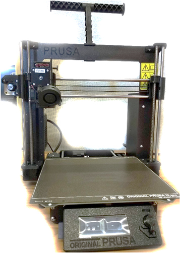
Figure 1. FDM Machine used for the fabrication.
Download figure:
Standard image High-resolution imageTable 1. Process parameters used for printing.
| Printing parameters | Values |
|---|---|
| Material | PETG |
| Print orientations | 0°, 45°, 90° and 45°/135° |
| Printing speed | 80 mm s−1 |
| Printing speed of external perimeter | 30 mm s−1 |
| Nonprinting speed | 150 mm s−1 |
| Retraction speed | 45 mm s−1 |
| Detraction speed | 25 mm s−1 |
| Filament diameter | 1.75 mm |
| Nozzle diameter | 0.4 mm |
| Infill percentage | 100 |
The different printing strategies are maintained by varying the print orientations namely 0°, 45°, 90° and alternate disposition of 45° and 135° as represented in figure 2. The angle of print orientations is considered according to the orientation of longer seams present in the component.
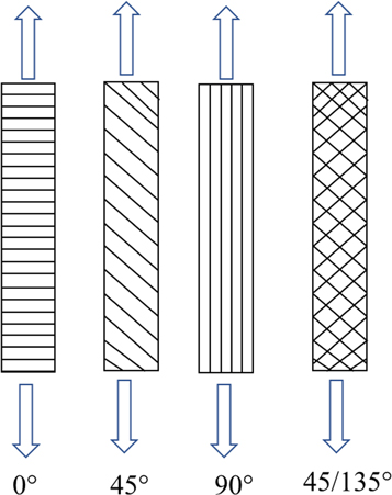
Figure 2. Schematic representation of different print orientations.
Download figure:
Standard image High-resolution imageThe 3D-printed samples are subjected to tensile testing to evaluate the stress-strain behavior. The universal testing machine of 5kN, Instron make, is employed to do the tensile test. The three specimens are fabricated at each condition and tested according to the ASTM E8M guidelines. During testing, the samples are loaded at a rate of 5 mm/min. The stress-strain values are acquired from the machine using the integrated load cell.
3. Results and discussion
Figure 3 shows the photographs of the 3D-printed samples of different orientations. It is observed that the printed samples have a reasonably good surface finish, and it is free from defects. The samples are noted to be free from geometrical distortions and the dimensions of the samples are according.
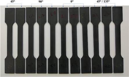
Figure 3. Photographs of the 3D printed samples.
Download figure:
Standard image High-resolution imageThe stress-strain behavior resulting from the tensile test is presented in figure 4. In all orientations, as the strain increases, the stress increases linearly. In 0° orientation, only the linear phase of stress increment is observed whereas in 45° and 45/135° the stress initially increases linearly and as the strain increases, further it loses its linearity and records a constant stress value before the sample gets failed. Comparing 45° and 45/135° orientations, the stress-strain behavior is similar. But the stress-strain behavior of the 90° orientation is different from the other orientations, specifically, the strain behavior. The stress values increase linearly as the strain increases and after attaining the peak stress-strain values, the curve gets dropped and stabilized for a large strain before rupture happens. It is important to emphasize that the 90° is the only orientation that shows a pure plastic stress-strain trend which is the inherent trend of PETG.
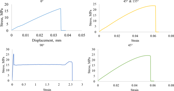
Figure 4. Stress-strain behaviour of different printing orientation.
Download figure:
Standard image High-resolution imageFrom the tensile test, the parameters of peak load and maximum displacement are extracted and considered for further analysis (figure 5). It is very evident that the 3D printed sample that was made at 0° orientation exhibits a lower peak load value of 628 N (figure 5(a)). The peak load values of the 3D printed sample made of 45°, 90°, and 45°/90° are almost similar. Nevertheless, at 90° orientation, the samples recorded a maximum load value of 942 N (figure 5(b)). On analyzing the maximum displacement value versus print orientation angle, it is clearly evident that the 3D printed samples made at 90° orientation outperform with a maximum displacement of 128 mm which is far higher than the other cases register 3 mm displacement. Hence it can be inferred that the print orientation has a strong influence on the peak load and the displacement values of the 3D-printed components.
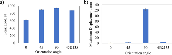
Figure 5. Influence of print orientation on peak load and displacement
Download figure:
Standard image High-resolution imageFigure 6 shows the photograph of the after-tested condition of the samples made of different printing orientations. From the fracture surface analysis, it is clearly evident that the print orientations have a stronger influence on deciding the location of the fracture and fracture path. For the sample made of printing orientation 90°, the fracture happened at the neck region of the hourglass tensile sample. In other words, the failure is not registered along the gauge length which is the center area that primarily experiences the tensile load. In a 90° oriented sample, the print seams are longer, continue and lie along the loading direction. Owing to this, the material is strong enough at the gauge length to withstand the tensile load and so the failure is looking for another weaker location to initiate. Since the curvature of the hourglass shape specimen acts as the stress concentrated region, the fracture initiates and falls at the curvature region of the sample. Whereas the samples fabricated using other print orientations display fractures at the middle of the component. The weaker interfaces lie normal or 45° towards the loading direction and so it is not able to withstand the tensile loading. In general, during the tensile load, the material will shear at an angle of 45° towards the loading direction and so it is obvious that the 45° oriented sample failed in the middle, and also the fracture path is 45°. This is also the reason for the early failure and record of lower displacement values (figure 5) for the other orientations. In the 0° print orientation, the interface between the print seams is perpendicular to the loading direction and so the fracture path is perpendicular to the loading direction. These interfaces connecting print seams are weaker and attract stress concentration. These interfaces exhibit thinning and micro or nano-level pores or lack of bonding during printing and so the interfaces are critical in deciding the tensile behaviour of the component. This observation and elucidation is agreeing with the previous reports [19, 22].

Figure 6. Fracture analysis.
Download figure:
Standard image High-resolution image
4. Conclusions
In this investigation, the hourglass-shaped PETG samples were fabricated using the FDM process. The samples are printed by varying the print orientations namely 0°, 45°, 90° and 45° /135°. Further, the samples printed at different orientations were analyzed and tested to evaluate the printing quality and mechanical properties. The tensile fracture surface of the failed samples during the tensile test was analyzed to identify the cause and modes of the failure. From the investigation, the following conclusions are framed.
Irrespective of print orientations, the print qualities are sound and free from defects like stringing, gaps, layer shifting, overs extrusion, layer separation, etc This is attributed to the fact that the print orientation has a lesser influence on the print quality and also due to the fact that the other predominant parameters like print temperature and printing speed were properly selected.
From the tensile test analysis, it was found that print orientation has an influence on the peak load values and a strong influence on the displacement values. The print orientation 90° offers a higher peak load of 942 N and displacement of 128 mm which is higher than the other orientations.
In the printed sample, the interconnection between the adjacent print seams is the critical region since the print seams should be well bonded. The other criticality is the reduction of thickness at the interconnections. In general, the tensile failure path preferably occurs at the sample 0° or 45° to the loading direction. The sample fabricated using 0°, 45°, and 45° /135° orientations, exhibits interconnections at the angles similar to the general tensile failure paths, 0° or 45° and therefore, it resulted in accelerated failure due to stress concentration at the interconnections. Moreover, the lower thickness of the interconnection offers low load-bearing capacity during the loading condition. Hence, the samples printed with 0°, 45°, and 45° /135° print orientations are exhibiting poor properties. The fracture analysis further confirmed that the fracture paths are approximately similar to the print orientation angles.
At the testing of the 90° print-oriented sample, the availability of continuous and longer print seam that supports load bearing and elongation due to lower stress concentration critical regions.
This study is a preliminary prior study towards the fabrication of thin-walled complex structures, which will be the future study. The observations from the current study will be useful for planning the printing strategies for complex geometries to avoid weak interconnections towards the tensile shear paths.
Data availability statement
All data that support the findings of this study are included within the article (and any supplementary files).