
Abstract
Recent progress in 3D printing has brought many interests in developing functional devices in various applications by enabling the exploration of complex 3D structures. This paper presents the first fully metal printed standalone 3D solenoid microinductors using a high-power laser with a biocompatible Ti-alloy. Fine powder-based 6AL-4V Eli Titanium was directly printed using an automated gantry laser system with 60 μm resolution to form the inductors without any substrate. A substrate-less 10-turn solenoid as a testbed was printed out and characterized, and additional designs of 20 and 40 turn inductors were further explored. The wire of the inductor was designed to have a 700-micron square cross-section and a winding gap of 300 microns. The successfully fabricated 10-turn titanium-alloy solenoid inductor showed an average inductance of 130 nH, a low-frequency resistance of 0.8 ohms at 0.3 MHz, and a quality factor of 10.5 at 30 MHz respectively. Additional electrodeposition of copper to the 10-turn inductor demonstrated process compatibility with the conventional micromachining process. The standalone inductor printing method saves a significant volume from where the conventional substrate dimensions often take more than the volume of the device. Also, the standalone inductor can directly be used as a sensor device. Examples of force-displacement sensing applications were presented using the 10-turn and 19-turn round edge solenoid inductors.
Export citation and abstract BibTeX RIS
1. Introduction
In recent years, titanium alloy base additive manufacturing (AM) has been widely studied for biomedical and aerospace applications [1, 2]. The aerospace industry dramatically benefits from additive manufactured Ti- alloyed parts that provide optimized structural properties and lighter weight. Consequently, it would save costly fuel consumption while providing the required mechanical properties. In medical applications, 3D printed Ti- alloy parts avoid the stress shielding effect due to their reduced Young's modulus [3–7]. A porous titanium structure provides good mechanical and functional properties for various implant applications [8–10]. Moreover, the Ti-alloy has proven its biocompatibility with minimal toxicity. One of the unexplored areas of 3D printed Ti-alloy applications is implantable sensors. Current studies of titanium alloy parts have been mainly focused on their mechanical properties, biocompatibilities, and manufacturing approaches. There are very few reports of sensor applications using titanium or titanium alloy [11]. Implantable sensor systems using 3D printed Ti-alloy would lead to a novel approach for various biomedical applications due to the inherited advantages from additive manufacturing. A small portion of the 3D printed Ti-alloy implants or an independently printed sensor can be designed to monitor the properties of implanted structures or biological signals. A passive sensing mechanism using a wireless connection would be suitable for the 3D printed Ti-alloy because the conductive nature of the material can be used to make resistors, capacitors, and inductors. Therefore, to develop 3D printed Ti-alloy sensor systems, it is necessary to study the electrical properties, such as conductivity, inductance, and capacitance of various structures.
An inductor is one of the essential components in many electronic and sensor devices [12–14]. Commonly used passive (battery-less) wireless sensors have an inductor for specific frequency response. To design passive sensors, 3D inductors are preferred over the 2D inductors as 3D inductors can constrain the magnetic field and have a smaller footprint. Microfabrication of inductors offers great potential for decreasing inductor size without sacrificing its performance. However, adopting a microfabrication process to form 3D geometry requires complicated and expensive processes including multiple mask alignments, high-vacuum-required metal deposition, and selective etching [15–17]. Moreover, the microfabrication process typically requires a substrate, which used to take a significant volume and often limit the sensor application as a free standing device. Therefore, the challenge is to develop a simple and low-cost fabrication approach without losing higher degrees of 3D design capability and miniaturization without sacrificing inductor performance.
In this paper, we introduce the fabrication of Ti-alloy 3D printed solenoid inductors. A 10-turn solenoid inductor as a reference was presented and followed by 20-turn and 40-turn wrapped solenoid inductors for demonstrating the versatility and the flexibility of the introduced 3D metal printings. The fully biocompatible metal powder, 6AL-4V Eli alloyed grade titanium, was used as a main 3D printing material which is also known as a popular implantable metal in various medical applications [18, 19]. The presented inductors were all electrically characterized in terms of inductance, resistance, and quality factor. Also, copper electroplating was introduced to the titanium-alloy inductors to show the broad process compatibility with the traditional micromachining process. The introduced copper electroplating to the inductor has resulted in improving the quality factor by lowering AC resistance.
2. Design and fabrication
A 10-turn solenoid inductor was designed as a test bed as shown in figure 1. The height of the inductor was 5 mm tall, and the width was designed as 4 mm, forming a 20 mm2 cross-sectional area. The square wire has a width of 700 μm, and the gap between the wires was 300 μm. The inductance of the proposed inductor was calculated using the fundamental inductance equation [17] as follows:

where  is the inductance of the solenoid inductor,
  is the relative permeability of the solenoid inductor core,
 is the permeability of free space,
 is the number of turns of the wire,
  is the area of the solenoid inductor core,
  is the length of the solenoid inductor. From equation (1), an average inductance of 130 nH was calculated from the 10-turn solenoid inductor. The adopted equation is valid for MHz ranges, so a good match between calculated and measured data was expected over the interested frequency range of 0.3–30 MHz.
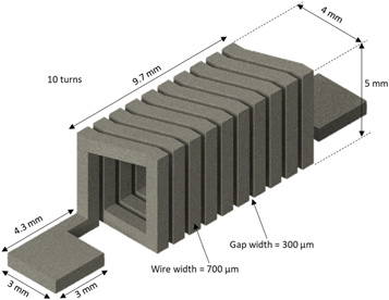
Figure 1. Design of 10-turn solenoid inductor.
Download figure:
Standard image High-resolution imageThe skin depth of the material in the targeted frequency should be considered to predict the resistance values. The skin depth equation was incorporated with the resistance value as shown in the following equations:


where  is the material resistivity (Titanium alloy = 1.724E-06 Ωm),
  is the relative permeability of the solenoid inductor core,
 is the permeability of free space,
 is the frequency,
  is the length of the wire,
  is the effective cross-sectional area of the wire,
  is the cross-sectional area of the skin depth of the wire, and
  is the cross-sectional area of the wire's surface roughness, respectively. The skin depth-related equations as presented in equations (2)–(4) assumed the skin depth as the main loss parameter. Other possible losses such as a proximity effect and a core loss are negligible because of the relatively large size of the presented designs of the air-core inductors and their operating frequency (less than 50 MHz). Well-alignment between the measurement and the calculated data in figure 5 supported this hypothesis.
A standard 3D metal printing of the 10-turn solenoid inductor was processed under the following conditions [20]. A high-resolution metal 3D printer (3D Systems, ProX DMP 320) was used for the metal frame printing. A fine powder of the commercial Titanium Grade 23 (Ti6Al4V ELI) was loaded up inside the 3D printer. Argon gas was introduced inside the chamber to prevent metal oxidation during the high-temperature process. A 60 μm resolution and a side step of 82 μm with extra-low interstitials were chosen in the printer option for the solenoid frames. A laser under computer numerical control mode formed an inductor structure by stereolithographic movement with a marked speed of 1250 mm s−1 and an applied power of 245 W. Several supporting pillars were created together with the inductor structure. After completion of the printing, those supporting pillars were removed.
The copper electroplating process is described as following. A copper (Cu) electrodeposition of 60 μm was performed using a commercially available electrolyte (Copper Mirror Plating Solution, Shor International, Co). Since the titanium-alloy structure was conductive, no seed metallic layer deposition was needed. The inductor was directly connected to a cathode of a DC power supply and submerged into the electrolyte. A current density of 20 mA cm−2 was applied for 30 min for 60 μm Cu deposition. The electroplated inductor was cleaned in deionized water and nitrogen-dried to complete the electroplating process.
Additional designs of the inductors were explored to take advantage of the versatile design capability of 3D metal printing, as shown in figure 2. A design of a 20-turn inductor as shown in figure 2(a) was folded in the middle to have two measurement pads close together. Four 10-turn inductors are connected in a folded and stacked manner as shown in figure 2(b). Both inductors in figure 2 have a substantial cross-sectional area for enough magnetic flux while keeping the compact footprint area, maximum utilization of inductor spaces, and optimal wiring design.
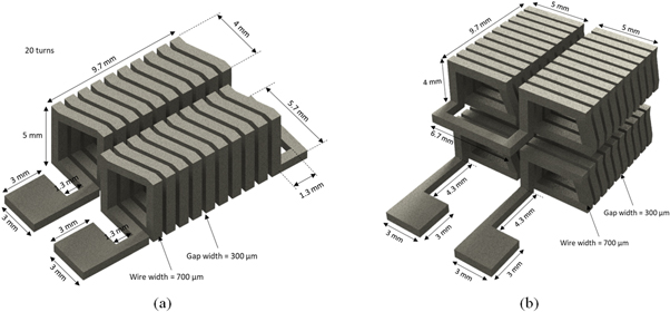
Figure 2. Design of (a) 20 and (b) 40 turn 3D design of inductors.
Download figure:
Standard image High-resolution image3. Result and discussion
The proposed 10, 20, and 40 turn solenoid inductors have been successfully fabricated and demonstrated as shown in figure 3. Figure 3(a) shows an overview of the 10 turn Ti-alloy inductor, and figure 3(b) shows the Cu electroplated 10-turn titanium inductor illustrating compatibility with the micromachining process. Figure 3(c) shows a 20 turn Ti-alloy solenoid inductor consisting of two 10-turn solenoid inductors in series. Figure 3(d) shows four 10-turn solenoid inductors where the two 10-turn inductors in series were printed on top of the other two 10-turn inductors illustrating the capabilities of 3D printing. The series connection structures shown in figure 3(d) can hold each 10-turn inductor to keep the overall inductor geometry including two hanging 10 turn inductor structures. The geometry of the 3D inductors after the metal printing process was shown as expected. However, a slight structure deformation such as the twisted look was found when the supporting pillars were removed. Those deformations could be resolved by optimizing the inductor design, the supporting pillar locations, or additional heat treatment under inert ambient.
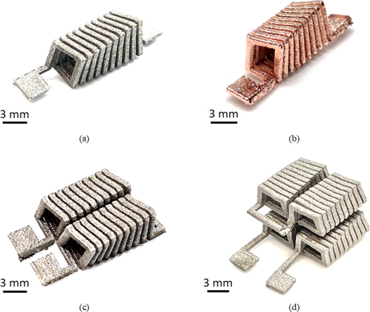
Figure 3. Fabricated inductors: (a) 10-turn titanium-alloy inductor, (b) 10-turn Cu electroplated inductor on the titanium backbone structure, (c) 20-turn folded inductor, and (d) 40-turn folded inductor.
Download figure:
Standard image High-resolution imageTo validate the electrical characteristics of the fabricated solenoid inductors, the 10-turn titanium inductor, with and without Cu electroplating, was calculated and compared with the measurement data as a function of frequency as shown in figure 4. While the predicted inductance and resistance models used equations (1) through (4), the inductance and resistance measurements were conducted using a network analyzer (HP8753ES). Inductances of approximately 130 nH for 10-turn Ti-alloy inductor and 105 nH for Cu electroplated 10-turn inductor were measured over the frequency range 0.3–30 MHz as shown in figure 4(a). The inductance of the Cu electroplated 10-turn inductor decreased as the electroplating process reduced the cross-sectional area of the inductor. The AC resistance and quality factor over the same frequency range are also shown in figures 4(b) and (c). The 10-turn Ti-alloy inductor and the Cu electroplated 10-turn inductor show low-frequency resistances of approximately 0.8 and 0.13 ohms at 0.3 MHz respectively. The quality factor at 30 MHz is 10.5 for the Ti-alloy inductor and 45 for the Cu-electroplated inductor. Since the copper has lower resistivity compared to the Ti-alloy, the measured low-frequency resistance of the Cu-electroplated inductor was lower than that of the Ti-alloy inductor and thereby resulted in a higher quality factor than the Ti-alloy inductor. The predicted and the measured inductances showed a good agreement.
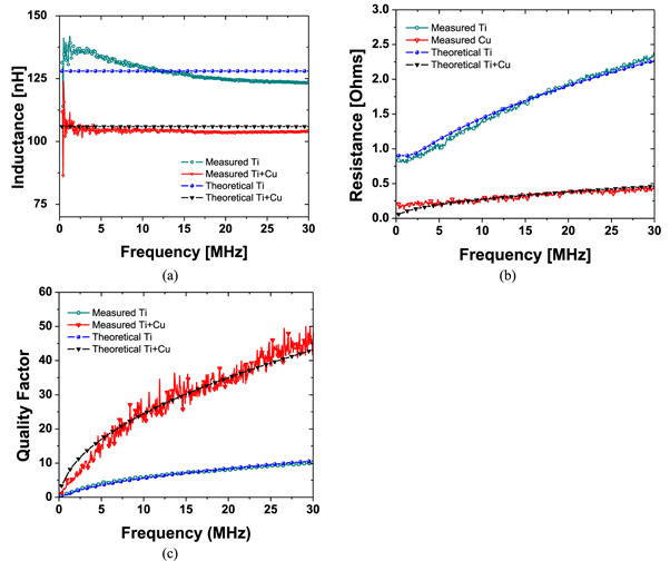
Figure 4. Prediction and measurement result of a 10-turn Ti-alloy (Ti) and Cu-plated Ti-alloy (Ti + Cu) solenoid inductors: (a) inductance, (b) resistance, and (c) quality factor.
Download figure:
Standard image High-resolution imageThe measurement results of 20-turn and 40-turn inductors are presented and compared with the predicted models in terms of inductance, resistance, and quality factor as a function of frequency as shown in figure 5. The 20-turn inductor has an average inductance of 260 nH while the 40 turn inductor has 512 nH over the frequency range of 0.3–30 MHz as shown in figure 5(a). The AC resistances over the same frequency range are approximately 1.56 ohms and 3.2 ohms at 0.3 MHz for 20-turn and 40-turn inductors respectively. The quality factors, at 30 MHz, were measured to be 10.7 and 8.3 for 20-turn and 40-turn inductors respectively. Below 30 MHz, predicted and measured results agree well.
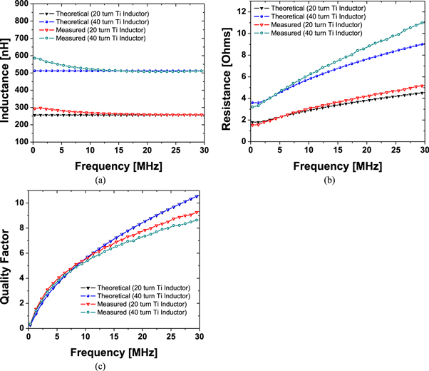
Figure 5. Measurement and prediction results of 20 and 40-turn solenoid inductor, (a) inductance, (b) resistance, (c) quality factor.
Download figure:
Standard image High-resolution imageTo validate the electrical characteristics of the toroidal inductor, the 3D geometries of 10, 20, and 40 turn inductors have been simulated using the Ansoft finite element HFSS tool as presented in figure 6. The simulation of the magnetic field flux of the 10-turn solenoid inductor is presented in figure 6(a). Simulated inductances and resistances of 10, 20, and 40 turn inductors, as shown in figure 6(b), agree, within 5%, with the measured value of each inductor.

Figure 6. Simulation results: (a) magnetic field distribution in the 10-turn solenoid inductor (b) Inductance and resistance result of 10, 20, and 40 turn inductors.
Download figure:
Standard image High-resolution imageTo demonstrate sensor applications, the variation of the inductance from the fabricated inductors has been tested as a function of a force-displacement. The inductance variations and geometry deformation by external contraction and expansion were investigated using the 10-turn Ti-alloy inductor and a 19-turn round-edge inductor as shown in figure 7. The 10-turn Ti-alloy inductor was first tested as a reference inductor as presented in figure 7(a). A force gauge (FC200, Torbal Inc.) was connected to one square measurement pad while the other pad was fixed. The inductance variation and the displacement as a function of applied force were observed. When the compression was applied up to −3 N, −1.5 mm displacement was observed with an increase of inductance of 143 nH. Further compression after −3 N short-circuited windings causing dramatically reduced inductance. Likewise, the expansion force was applied up to 4 N and observed a linear decrease of inductance down to 108 nH with the expanded displacement of 2 mm. A nonlinear relationship of external force to variation of inductance and displacement can be created by designing and fabricating the 3D printed inductor as shown in figure 7(b). A 19-turn round-edge inductor was designed and 3D printed using the same method as shown in the inset of figure 7(b). The force inductance-displacement experiment was conducted identically. The initial inductance was 210 nH, and the inductance rapidly increased up to 239 nH when the expansion force increased to 0.5 N. Then the inductance remains constant around 244 nH as the force applied ranges from 1.5 to 2.5 N. After 2.5 N of applied expansion force, winding shorts around the rounded portion of the inductor was observed by the stark inductance drop at 3 N and 3.5 N while the displacement was maximized at 12 mm. The force inductance-displacement experiments presented in figure 7 were repeated multiple times and any deformation from the original shape was not found. As the experiment results demonstrated, the presented inductors can be packaged and used as an implantable pressure sensor, e.g., blood pressure for aneurysm detection, heartbeat sensing, etc.

Figure 7. Sensing behavior tests of (a) 10 turn inductor and (b) 19-turn round edge inductor.
Download figure:
Standard image High-resolution image
4. Conclusions
Various standalone 3D printed Ti-alloy inductors were fabricated by using a high-resolution metal 3D printer and the fabricated inductors demonstrated their performance in terms of inductance, resistance, and quality factor. A substrate-less direct 3D metal printing approach was able to not only save the overall volume of the device but also directly use it as a pressure or strain sensor.
As testbeds, 10-, 20-, and 40-turn solenoid inductors were designed and successfully printed out. Each inductor was characterized in terms of inductance, resistance, and quality factor. Measured inductances of 130, 260, and 512 nH from 0.1–30 MHz, and low-frequency resistances of 0.8, 1.56, and 3.2 Ω resulted for 10-, 20-, and 40-turn solenoid inductors respectively. The corresponding quality factors at 30 MHz are 10.5, 10.7, and 8.3. The measurement results were well aligned to the predictions from HFSS simulations, where each inductor showed its completive performance compared to the similar dimensions of other inductors.
The introduced metal printing process showed compatibility with the conventional electrodeposition process. The 10-turn metal inductor was directly copper-electroplated without the predisposition of a typical metal seed layer. 60-micron additional copper coatings significantly lowered resistances over the operating frequency range and thereby increased the quality factor.
Compression and expansion tests were conducted on the free-standing metal inductors and we observed a linear relationship between applied force and inductance/displacement from the 10-turn Ti-alloy inductor. A nonlinear relationship from the 19-turn round-edge Ti-alloy inductor demonstrates the versatility of 3D metal printing and its possible applications.
The introduced methods highlight the ease and speed of 3D fabrication. This is the first fully titanium alloy-based 3D printed inductors that have great potential as implantable sensors and actuator microdevices. While conventional micromachined inductors necessitate dead volume substrates, the proposed fabricated inductors can be printed out as standalone components. We also demonstrated a simple sensor device using the 3D printed Ti alloy structures. The printed metal structure showed a robust, repeatable, and reliable sensing capability. The presented metal 3D printing method has great potential in realizing a broad range of implantable devices with sensing and actuation capabilities.
Acknowledgments
Jungkwun 'JK' Kim acknowledges partial financial support from the National Science Foundation (ECCS-2029086). S J Kim acknowledges partial financial support from NASA (Grant#-80NSSC20K1204). The authors thank Dr. Charles Tomonto at the Johnson & Johnson 3D Center of Excellence at the University of Miami for his help in metal printing.
Data availability statement
All data that support the findings of this study are included within the article (and any supplementary files).
CRediT authorship contribution statement
Jun Ying Tan: Experiment, Characterization, Mark Ciappesoni: 3D printing, Editing, Sung Jin Kim: 3D printing, Writing- Reviewing and Editing, Jungkwun 'JK' Kim: Conceptualization, Writing, Supervision, Methodology.
Declaration of competing interest
The authors declare that they have no known competing financial interests or personal relationships that could have appeared to influence the work reported in this paper