
Abstract
The burning of fossil fuels in industry results in significant carbon emissions, and the heat generated is often not fully utilized. For high-temperature industries, thermophotovoltaics (TPVs) is an effective method for waste heat recovery. This review covers two aspects of high-efficiency TPV systems and industrial waste heat applications. At the system level, representative results of TPV complete the systems, while selective emitters and photovoltaic cells in the last decade are compiled. The key points of components to improve the energy conversion efficiency are further analyzed, and the related micro/nano-fabrication methods are introduced. At the application level, the feasibility of TPV applications in high-temperature industries is shown from the world waste heat utilization situation. The potential of TPV in waste heat recovery and carbon neutrality is illustrated with the steel industry as an example.
Highlights
The state of the art of the thermophotovoltaic (TPV) generation on heat recovery is highlighted.
At the system level, representative results of TPV systems and components are compiled.
At the application level, feasibility of TPV in high-temperature industrial applications is exhibited.
Key points of TPV systems to improve energy conversion efficiency are further analyzed.
Export citation and abstract BibTeX RIS

Original content from this work may be used under the terms of the Creative Commons Attribution 4.0 license. Any further distribution of this work must maintain attribution to the author(s) and the title of the work, journal citation and DOI.
1. Introduction
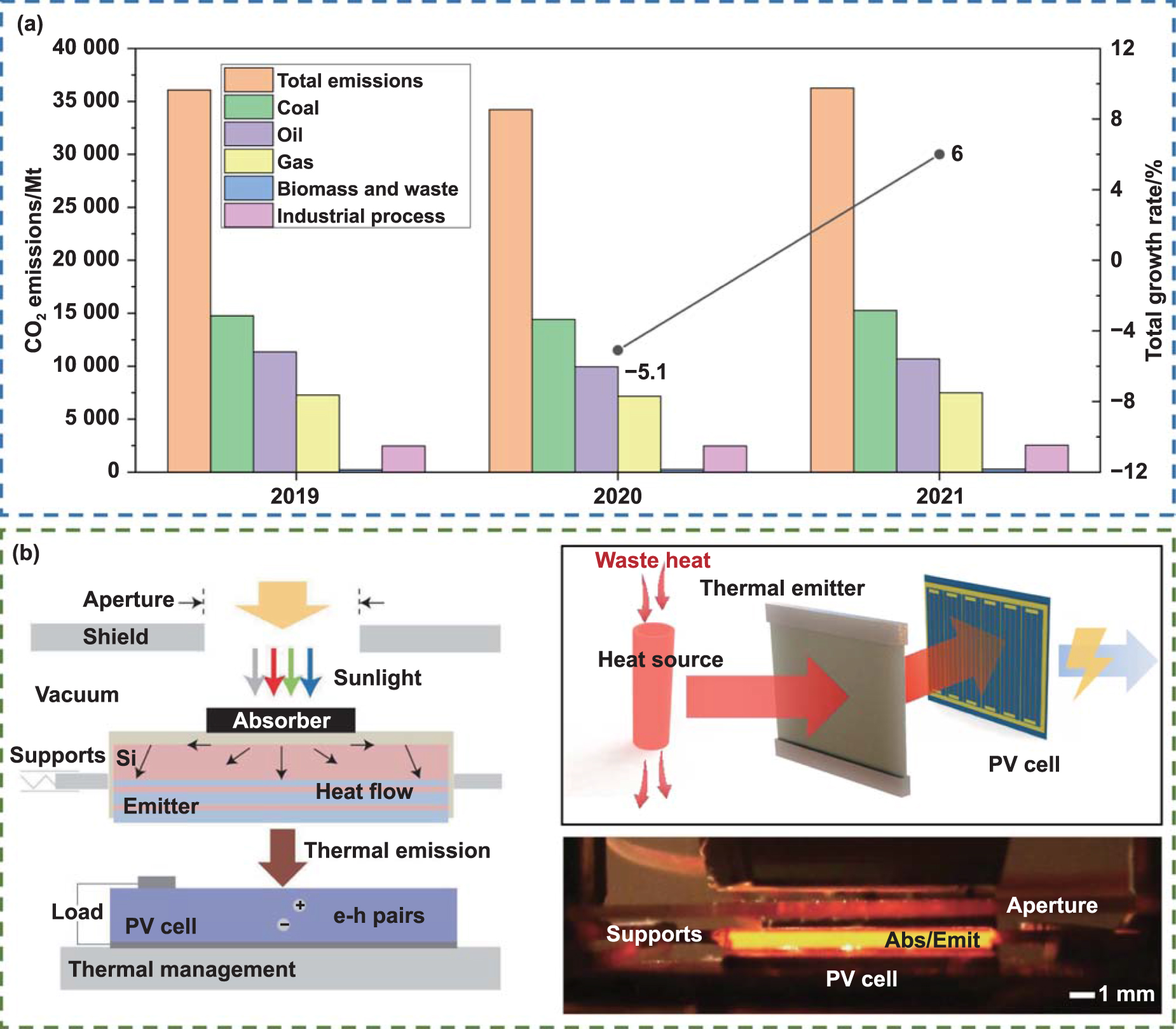
The development of human society consumes a considerable amount of energy yearly. As the world economy recovers from COVID-19 lockdowns, carbon emissions rise sharply [1–3]. The burning of fossil fuels produces significant amounts of carbon emissions [4, 5]. As shown in figure 1(a), fossil fuels are at the forefront of energy and process CO2 emissions, dominating the world's energy supply. The arrival of the 'double carbon' era indicates the imperative of carbon reduction in energy-intensive and high carbon industries [6]. However, the heat generated from processes with high carbon emissions cannot be fully utilized [7, 8]. The process of converting energy, including other energy sources, into a form that can be used directly always generates significant waste heat [9–11].
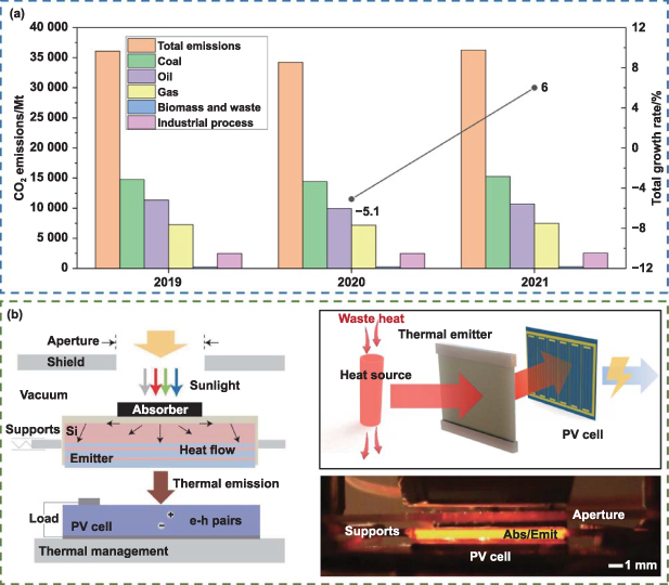
Figure 1. CO2 emissions and the typical TPV system. (a) CO2 emissions from 2019 to 2021. Based on IEA data from IEA (2022) Global Energy Review: CO2 Emissions in 2021, www.iea.org/statistics. All rights reserved; as modified by Chen Shuni [12]. (b) The main components of the TPV system for heat recovery, taking the nanophotonic solar thermophotovoltaic (STPV) device studied by Lenert et al as an example [13]. Reproduced from [13], with permission from Springer Nature.
Download figure:
Standard image High-resolution imageIn particular, the greatest amount of waste heat is lost in industrial and energy production processes. Studies estimate that approximately 20%–50% of industrial energy consumption ends up as waste heat, and that 18%–30% of this waste heat can be utilized [14]. The rapid depletion of conventional energy sources has led to the urgency of improving the efficiency of energy conversion; in particular, the ideal method is the efficient utilization of waste heat. To meet the requirements, one of the potential candidates is thermophotovoltaic (TPV) devices [15].
TPV devices have been researched and developed since the 1960s, initially only as a replacement for thermoelectric and thermionic devices, used as a direct energy conversion device [16]. After a period of silence, with the rise of the semiconductor industry and microfabrication technology, there was widespread interest in TPV systems for power generation after the 1990s. Furthermore, they have been applied in automotive, military, space, and other fields [17–20].
The principle of the TPV system is mainly based on the photovoltaic (PV) effect. The phenomenon of electromagnetism radiation incident on the p–n junction generates an electric potential [21–23]. The system consists of three main components: a heat source that provides energy, a heat emitter that converts heat energy into an emission spectrum, and a PV cell that converts photon radiation into electrical energy [24]. The process is shown in figure 1(b). For TPV systems, the heat source can be solar radiation [25, 26], radioactive isotopes, chemical fuel combustion [27], and other processes that can release large amounts of heat, which also includes the recycling of waste heat. Different types of TPV systems are shown in figure 2.
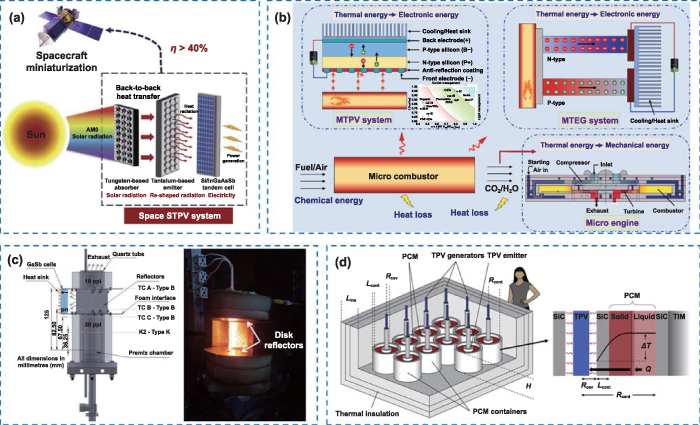
Figure 2. Different types of TPV systems. (a) A space STPV system [28]. Reprinted from [28], © 2022 The author(s). (b) The micro scale combustion based power system [29]. Reprinted from [29], © 2022 Elsevier Ltd. All rights reserved. (c) Porous media combustion-based thermophotovoltaic (PMC-TPV) system [30]. Reprinted from [30], Crown Copyright© 2019 Published by Elsevier Ltd. All rights reserved. (d) Latent heat thermophotovoltaic (LHTPV) battery [20]. Reprinted from [20], ©2022 Elsevier.
Download figure:
Standard image High-resolution imageThe main way in which TPV waste heat is recovered is by collecting the waste heat generated by various processes, and the thermal radiation enables the PV cells to generate electricity. Especially in high-temperature industries, such as the steel and glass industries, the application of TPV is promising [26]. In recent years, to recover waste heat, TPV systems have been used in automotive exhaust gas treatment, fuel cells, and other applications [31].
However, most of the research on TPV has been devoted to solving the problem of low efficiency, which is the main factor preventing the large-scale adoption of TPV devices. The mismatch between the emission spectrum of the heat emitter and the bandgap of the PV cell is the main reason for the inefficiency of the system [32, 33]. Only the part of the energy supplied by the heat source to the heat emitter that exceeds the power of the PV cell energy gap can be converted into electrical energy; the rest of the energy is reflected back into the emitter or becomes heat loss [34]. The more severe the energy mismatch, the greater the resulting heat loss.
Currently, two main approaches are considered for addressing inefficiencies. The first is to enhance the matching of the thermal emitter emission spectra to allow efficient recirculation of emitted photons. This is reflected in the development of emitter structures with spectrally selective emission [35] or the addition of filter structures [36]. The former has been popularly researched in recent years. The second is to develop suitable narrow bandgap PV cell materials to allow more photons with lower energy to be absorbed by the cell [37].
This review focuses on the efficiency improvements of TPV systems and the potential of TPVs for heat recovery applications. For the possible improvement of the system efficiency, firstly, we specify the destination of the system heat that causes the reduction of efficiency. Subsequently, we introduce the thermal emitters and PV cells that are closely related to the improvement of the system efficiency. The evolving, rough-to-precise manufacturing methods of both are highlighted. Additionally, for applications of waste heat recovery, existing overall research is first presented, followed by an analysis of the potential of TPV waste heat recovery on the example of the steel industry.
2. Efficient heat utilization by improving the efficiency of TPV systems
2.1. Thermal dissipation of TPV
The TPV efficiency is related to each part of the system. From various heat sources  , the energy is supplied to the emitter with a certain heat loss
  , next the emitter generates radiated power
  to the PV cell. The radiated power
  consists of two components,
  and
and  . The transformed part of radiated energy from the emitter
  should exceed the power with energy gap, and the loss
  is caused by photons with energy below the energy gap of the PV cell. These photons with power
  are recycled to the emitter to conserve heat at the desired emitter temperature and to reduce
  [38]. This process can be seen in figure 3(a).
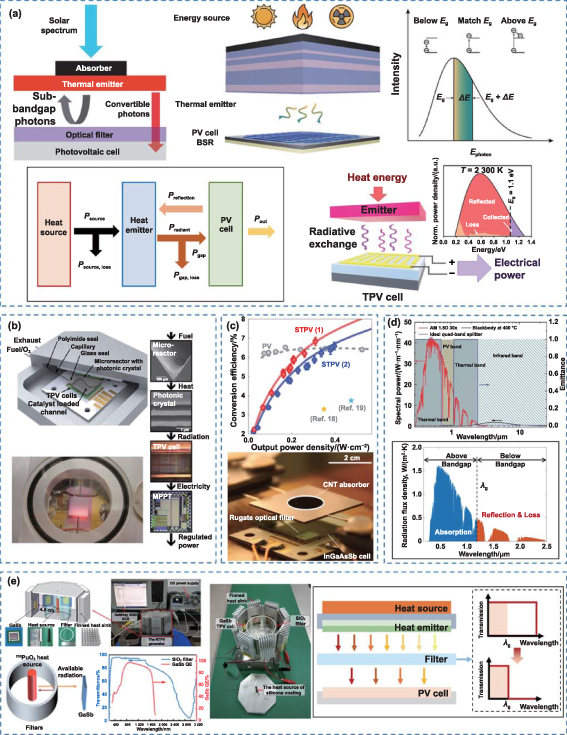
Figure 3. The principle and efficiency of TPV. (a) Energy flow during TPV working progress [34, 39, 40]. Reproduced from [34], with permission from Springer Nature. Reprinted with permission from [39]. Copyright (2016) American Chemical Society. Reprinted with permission from [40]. Copyright (2022) American Chemical Society. The heat from the heat source is transmitted to the heat emitter. From the emitter, the portion of the energy emitted above the bandgap of the PV cell is absorbed and the rest is reflected. There are losses in each step of this process. (b) Chan et al experimentally demonstrated 2.5% efficiency with a μTPV system design which is much simplified [41]. Reproduced with permission from [41].pans Copyright (2013) National Academy of Sciences. (c) Bierman et al measured up to 6.8% efficiency in converting solar energy to electricity with an STPV system [34]. Reproduced from [34], with permission from Springer Nature. (d) The main causes of TPV inefficiency [42]. [42] John Wiley & Sons. © 2016 WILEY-VCH Verlag GmbH & Co. KGaA, Weinheim. The emission spectrum does not match the bandgap of the PV cell, taking Si cells as an example. (e) The addition of a conventional filter structure allows photons with energy above the bandgap to reach the PV cell [43]. [43] John Wiley & Sons. © 2019 WILEY‐VCH Verlag GmbH & Co. KGaA, Weinheim.
Download figure:
Standard image High-resolution imageThe energy efficiency of the heat source to the emitter can be expressed as follow:
where  is the total emitted power of the thermal emitter, which is presented as:

Also, from the previous analysis, it is known that  can be expressed as:

The spectral efficiency of the emitter is given by [44]:
where  is the wavelength corresponding to the forbidden band width of the PV cell,
  is the blackbody spectrum and
  is the spectral emissivity of the emitter.
For the PV cell, its conversion efficiency to the emitter emission spectrum can be expressed as [45]:
The efficiency of the TPV system in converting radiant heat to electrical power can be represented as [46]:
And the TPV efficiency for the generating process of electric power from the thermal emission can be represented as [47]:
TPV systems have been investigated in their entirety by many research institutes, with simple flat TPV systems and stereoscopic TPV systems for practical applications respectively. Two typical examples are presented here. Chan et al proposed a method predicted to achieve 32% thermoelectric conversion efficiency within a millimeter-scale form factor in 2013. They made a much-simplified system with a theoretical efficiency prediction of 2.7%, as shown in figure 3(b), demonstrating 2.5% efficiency experimentally. The system can generate 344 mW of electric power in an area of 1 cm2, with the microcombustor temperature up to 800 °C to input 13.7 W thermal power [41]. That means the heat loss therein is still significant. As the design volume increases, the experimentally measured efficiency would probably decrease even more compared to the predicted. The other is the STPV system studied by Bieman et al published in 2016, as shown in figure 3(c). The solar-to-electric conversion rate of (6.8 ± 0.2)% exceeded the performance of PV cells alone. The overall efficiencies for the particular experiment are expected to reach 10% [48–50]. However, this system is more inclined to device performance testing, of which the structure is relatively simple. The experiments only discussed system output power at varying input power. For STPV, the input power of the solar energy varies in practical applications as well. In general, the TPV systems currently under study are constantly improving in efficiency due to the optimization of the components.
For flat systems, the research results for the decade 2012–2022 are shown in table 1. Flat panel type systems are mainly studied physically because of their simple structure. The efficiency of the flat system can be seen to hardly exceed 10% under operating conditions, both in physical experiments and numerical models. On the structural side, the reason for the inefficiency is the loss of the view factor due to the flat system [51].
Table 1. The research of flat TPV systems from 2012 to 2022.
| Research content | Feature | TPV efficiency | Published year | References |
|---|---|---|---|---|
| A novel cascading TPV and TE power generation system | Experimental | 5.2% at 1509–1558 K | 2012 | [52] |
| Chip-scale thermophotovoltaics | Experimental | 2.5% at 973 K | 2013 | [41] |
| NARO-STPV | Experimental | 3.2% at 1235 K | 2014 | [13] |
| STPV with a monolithic planar selective emitter | Experimental | 8% at 1640 K | 2015 | [53] |
| STPV with an optical filter and a photonic crystal emitter | Experimental | 6.8% at 1573 K | 2016 | [34] |
| TPV power generator based on a dielectric-encapsulated 2D photonic crystal | Numerical | 7.57% at 400 sun | 2017 | [54] |
| TPV device with a porous superadiabatic radiant burner | Experimental | 3.1% at 1250 K | 2018 | [55] |
| Metamaterial-based near-field TPV system | Numerical | 6.22% at 2200 K | 2019 | [56] |
| STPV system with a nanostructure-based selective emitter | Experimental | 8.4% at 1676 K | 2020 | [57] |
| Efficient NFTPV energy conversion | Experimental | 6.8% at 1270 K | 2021 | [58] |
| Solar thermophotovoltaic-thermoelectric (STPV-TE) system | Experimental | 5.91% at 1373 K | 2022 | [59] |
For stereoscopic system, the research results for the decade 2012–2022 are shown in table 2, in which no relevant literature published in 2016 is found. Most of the stereoscopic systems present a nearly cylindrical structure. Due to the different structural designs and uses, the efficiency of the system also presents a large difference. The emitter of the stereoscopic TPV system can be surrounded by PV cells in almost all directions, theoretically minimizing the view factor loss [60]. However, most of the measured efficiencies obtained in the literature are below 1%. It takes into account that the flat system is oriented towards theoretical verification, while the stereoscopic system is oriented towards practical applications [61]. The studies published in recent years on practical stereoscopic systems have focused on numerical simulations for parameter optimization, and few experiments have been conducted to measure specific efficiency results in detail. This also indicates that the design of stereoscopic system forms is not the major challenge for TPV application-oriented research. The main problem remains the low energy conversion efficiency of TPV components.
Table 2. The research of stereoscopic TPV systems from 2012 to 2022.
| Research content | Feature | TPV efficiency | Year | References |
|---|---|---|---|---|
| Micro-TPV device | Experimental | 2.12% at 1000–1600 K | 2012 | [62] |
| A complete solar thermophotovoltaic system | Experimental | 0.73%–0.85% under 750–800 W·m−2 sun | 2013 | [63] |
| Micro-thermophotovoltaic power generator with heat recuperation | Experimental | 0.93% at 1.26 W with recuperator | 2014 | [64] |
| Radioisotope thermophotovoltaic system with photonic crystal spectral control | Numerical | 7.8% with 5.5 W | 2015 | [65] |
| A TPV system consisting of a composite radiant burner and combined cells | Experimental | 3.72% by a two-temperature prototypical system | 2017 | [66] |
| A cylindrical thermophotovoltaic cell | Numerical | ∼28% at 773 K | 2018 | [67] |
| A porous media combustion-based TPV reactor | Experimental | 0.071% at 1558 K | 2019 | [30] |
| Optical cavity associated TPV system | Numerical | 10.01% at 1470 K | 2020 | [68] |
| TPV system with the three-sided emitter | Numerical | 12.36% at 1900 K | 2022 | [69] |
The low efficiency of TPV systems is mainly caused by the mismatch between the emission spectrum of the emitter and the bandgap of the PV cell [70], as is shown in figure 3(d). To improve the TPV efficiency, there are generally two mainstream ideas. One is to enhance the effective emission and recirculation of emitted photons. A typical solution is to add filters [34], as can be seen in figure 3(e). Increasing the spectral selectivity of the emitter can replace the filter structure. The second is to develop materials for PV cells with narrow energy gaps [71]. These will be described in the next section.
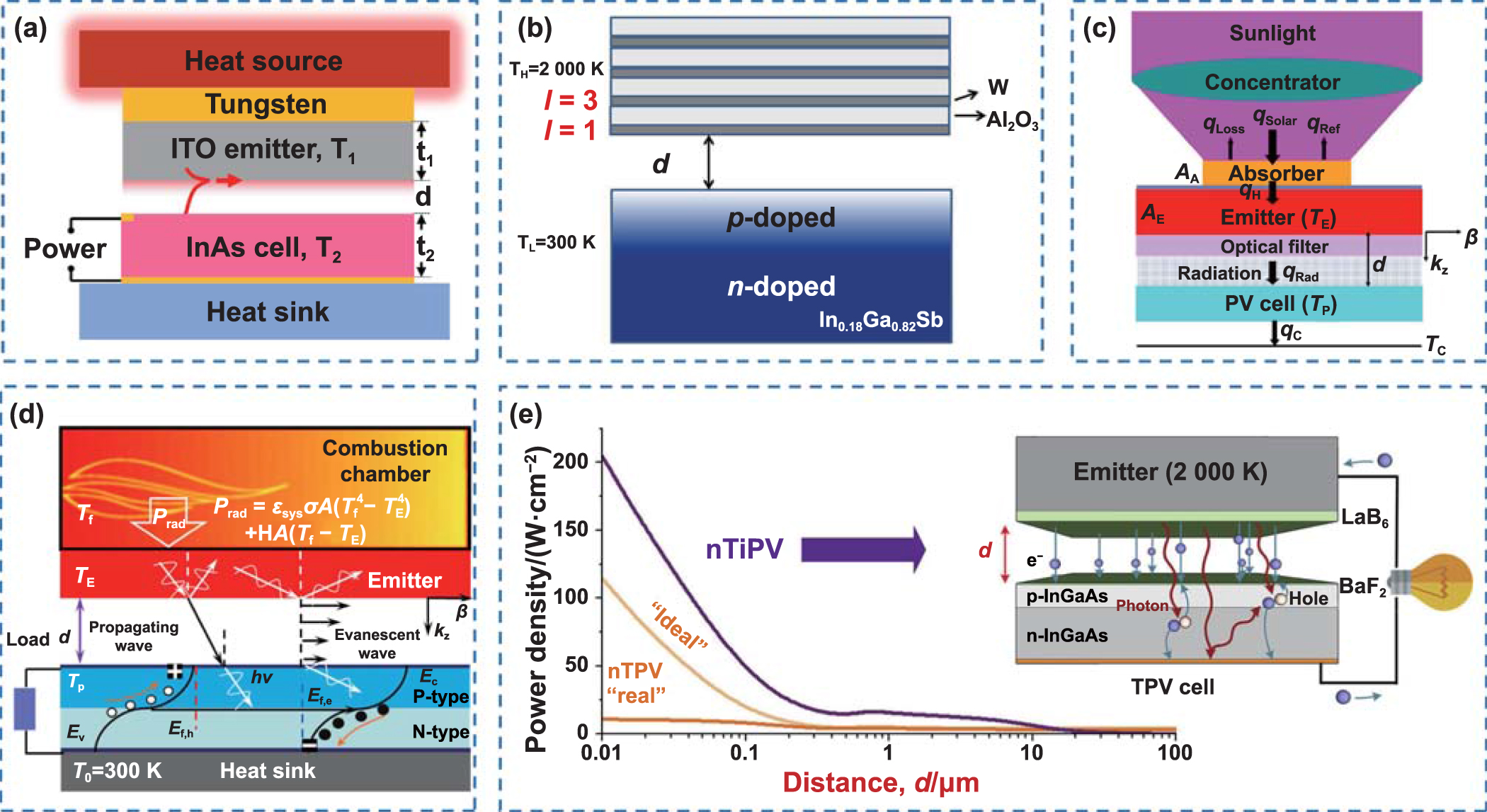
However, such far-field radiative heat transfer has limited power density of TPV, because in the far field, only propagating wave channels can be utilized to transfer energy; thus, the heat transfer is fundamentally restricted by the blackbody limit [48–50]. Reducing the spacing of hot and cold bodies to less than the thermal wavelength can significantly enhance the photon flux between them by placing the bodies in the 'near field' (NF) of each other [72–74]. In NF, under the influence of photon tunneling and evanescent waves, the intensity of radiation is greatly increased [75, 76]. Due to the potential for high-power density and high-efficiency energy conversion, TPV technology with near-field evaporation modes has been actively explored in recent years, as shown in figure 4. While some qualitative experimental efforts based on numerical calculation have demonstrated the potential of near-field thermophotovoltaic (NFTPV), systematic studies are not possible now owing to the immaturity of the technology, which involves achieving and sustaining large temperature differences and stable nanoscale spacing between hot and cold bodies [58]. Therefore, this study focuses on the status of research on far-field TPV.

Figure 4. Examples of NFTPV. (a) Schematic of the NFTPV system, with the ITO emitter and the InAs cell [48]. Reprinted from [48], © 2017 Elsevier Ltd. All rights reserved. (b) An NFTPV system configuration using a multilayer emitter. The emitter consists of alternating layers of tungsten and aluminum oxide, with tungsten as the top layer [77]. Reprinted from [77], used with permission of American Society of Mechanical Engineers ASME, from Yang et al (2017 J. Heat Transfer 139 052701); permission conveyed through Copyright Clearance Center, Inc. (c) A novel near-field solar TPV system consisting of a concentrator, an absorber, an emitter, a filter, and a PV cell that can efficiently convert a portion of the solar energy into electrical energy [78]. Reprinted from [78], © 2017 Elsevier Ltd. All rights reserved. (d) A fuel-driven NFTPV system comprising a combustion chamber, a furnace, a regenerator, a transmitter, a selectivity filter, and a PV cell [79]. Reprinted from [79], © 2023 Elsevier Ltd. All rights reserved. (e) A thermionic-enhanced NFTPV device. The emitter and PV cell are both covered with low work function coatings (which emit and collect electrons) and separated by nanoscale vacuum gaps [80]. Reprinted from [80], © 2019 Elsevier Ltd. All rights reserved.
Download figure:
Standard image High-resolution image2.2. Modulation of the emission spectrum
TPV system emitter temperatures are typically in the range of 1000–2000 K for PV cells with bandgap between 0.5 eV and 0.75 eV. As mentioned in the previous section, photons with energy higher than the bandgap of the PV cell will be absorbed to generate electricity, while the rest will be reflected to increase heat source temperature, or dissipated. This improves the efficiency of the TPV system [33]. Filters are TPV components that filter out photons with energy exceeding the bandgap in the emission spectrum. The early filters were placed as separate devices between the emitter and the PV cell [81]. Selective emitters were proposed a few years later than filters [82], but have been extensively studied in the last decade. It is a combination of a filter and an emitter. The filter is no longer used as a separate component, but is attached directly to the emitter. The selective emitter emits the same spectrum as a normal emitter filtered by the filter, but it makes the spectrum match the PV cell bandgap with just one component.
The selective emitters that were studied in the 1990s and early 2000s were mainly rare-earth doped emitters [83] and bulk emitters based on W, Ta, Si or SiC [84, 85]. For rare-earth doped emitters, a typical example is the Yb2O3 and Er2O3 emitters studied by Paul Scherrer Institute in 2002. The Yb2O3 emitter has an emissivity  and photon energy
  at 1735 K, and the Er2O3 emitter has an emissivity
  and photon energy
  at 1680 K [86]. For bulk emitters, they naturally have a broadband intrinsic emissivity [51]. A micro-TPV power generator with a SiC emitter studied by Natl Univ Singapore in 2004 can provide 0.92 W of electrical energy in a micro-combustor with a volume of 0.113 cm3 [87]. Due to the simplicity of preparation, this type of structure has also found some applications in recent years [88, 89]. But the devices are more focused on components that enable the full utilization of heat [55].
Metamaterial, especially photonic crystals, as a research hotspot in recent years, have a promising future in the preparation of TPV emitters [90–95]. Its precise geometry and dimensions are smaller than the wavelength at which it acts, thus allowing it to exert its influence on the wave [96–99]. Therefore, the emission spectrum can be precisely tuned by adjusting the microstructure of the metamaterial [100–102]. This can result in a significant thermoelectric conversion efficiency. The conventional structural design method iteratively optimizes the required parameters by solving Maxwell's system of equations and full-field electromagnetic properties, based on parameters such as geometry, boundary conditions, and mesh density, after a large number of repetitive scan-type calculations [103, 104]. With the development of computer performance, algorithms such as particle swarm optimization and genetic algorithm are gradually applied to the design of spectral modulation [104–106]. A further design approach is the use of machine learning models to learn the accumulated arithmetic samples to obtain the mapping relationship between structural parameters and spectra, which in turn enables fast inverse design [107, 108]. The research on metamaterial emitters from 2012 to 2022 is listed in table 3. As shown in the table, the emission spectrum of the emitter can be tuned to the PV cell bandgap range by the microstructure. The high emissivity range of the emitter is typically below 2 μm wavelength, matching the bandgap of most PV cells. The emitters are generally composed of two or more materials, and accordingly equipped with a periodic structure [109–111], or a multilayer membrane design [112–115]. Cyclical structures may be added based on multiple layers [116, 117]. Figure 5 shows examples of nano/microscale spectral modulation in recent years.

Figure 5. Examples of nano/microscale spectral modulation. (a) Polarized photonic devices with QBIC resonances determined by nanodielectric strip design, studied by Tan et al [118]. [118] John Wiley & Sons.© 2021 Wiley-VCH GmbH. (b) Hou et al integrated a near-infrared pentamer ONAs arrays with few-layer MoS2 as photodetectors [119]. Reprinted from [119], © 2018 Elsevier Ltd. All rights reserved. (c) Heterostructures comprising of a resistive microheaters integrated with a phase-change metasurfaces, studied by Abdollahramezani et al [120]. Reproduced from [120]. CC BY 4.0. (d) A hypersurface consisting of a periodic array of identical GSST meta-atoms was designed by Zhang et al. The meta-atom dimensions were chosen so that the meta-atoms support two unique hybrid plasma-photon modes [121]. Reproduced from [121], with permission from Springer Nature.
Download figure:
Standard image High-resolution imageTable 3. The research of metamaterial emitters from 2012 to 2022.
| Research content | Feature | Structure | High emissivity range | Year | References |
|---|---|---|---|---|---|
| Wavelength-selective and diffuse emitter enhanced by magnetic polaritons | Numerical | A 1D tungsten grating structure with a silica spacer on a tungsten film | 0.62–1.98 μm | 2012 | [122] |
| Three-dimensional self-assembled photonic crystals | Experimental | Conformal deposition on silica colloidal crystal templates using ALD | <2 μm | 2013 | [123] |
| Heterogeneous metasurface | Experimental | An array of platinum crosses above a platinum backplane with an amorphous Al2O3 spacer layer | <2 μm | 2014 | [124] |
| 1D trilayer films grating with W/SiO2/W structure | Numerical | Combine the periodic grating and MIM structure | 0.9–1.8 μm | 2015 | [125] |
| Refractory epsilon-near-zero metamaterials via topological transitions | Experimental | Refractory metal tungsten (20 nm layers) and a transparent dielectric hafnium dioxide (100 nm layers) on a 100 nm tungsten substrate | <1.5 μm | 2016 | [126] |
| One-dimensional metallodielectric (W/SiO2) photonic crystal | Experimental | 2 repeated bilayers of dielectric and metallic layers and an additional dielectric layer | <1.8 μm | 2017 | [127] |
| High-temperature refractory metasurfaces | Experimental | A unit cell comprising four W-nanodisks of different diameters fabricated by using electron beam lithography (EBL) methods with DC sputtered tungsten and atomic layer deposited (ALD) Al2O3 films | <1.1 μm | 2018 | [128] |
| A 1D structured emitter based on a sputtered W-HfO2 layered metamaterial | Experimental | Six bilayers of W and HfO2, with thicknesses of 20 and 100 nm | 0.6–1.5 μm | 2019 | [129] |
| A micro-textured absorber and a multilayer selective emitter fabricated on a W substrate | Experimental | Two layers of 160 nm Si3N4 dielectric and a 40 nm W layer sandwiched in between | 0.3–1.342 μm | 2020 | [57] |
| Spectrally selective emitters based on 3D Mo nanopillars | Experimental | A single metal layer of Mo with an 80 nm thickness over 3D Si structures | 0.8–2 μm | 2021 | [130] |
| Nanolayered wavelength-selective narrowband thermal emitters | Experimental | A TPP-based thermal emitter composed of SiNx /SiNy Oz (SiN/SiNO) multilayers and a tungsten (W) film on a silicon (Si) substrate | 1.7–1.9 μm | 2022 | [131] |
Although the metamaterial emitter can achieve good spectrally selective emission, it still has many problems in practical applications [108]. Since TPV systems are frequently operated in the environment above 1000 K, many emitters emit irreversible changes in their properties at high temperatures, causing significant adverse effects on selective emissivity. For example, at high temperatures, metal layers can oxidize and some materials can evaporate [132]. The prevailing solution is to deposit a protective coating on the emitter surface. Several studies have shown that the optical performance of the emitter with the addition of HfO2 protective layer can remain stable at temperatures above 1000 K [128, 133]. There is also the choice of refractory materials [134], such as TiN, in the construction of the emitter for thermal stability performance from the material itself.
For early TPV emitters, as shown in figure 6(a), thermal spraying was commonly used for rare earth metal launchers. Thermal spraying is a process in which the coating material is heated and melted, atomized into significant fine particles with a high-speed air stream, and sprayed onto the surface of the workpiece at a considerably high speed to form the coating. Bulk emitters consisting of a single substance can be made using simple mechanical methods, as can be seen in figure 6(b). With the development of technologies such as atomic layer deposition (ALD), electron beam evaporation, and magnetron sputtering, metamaterial emitters with various microstructure designs have been prepared [135–137].

Figure 6. Conventional emitter preparation methods. (a) Rare earth metal emitters are prepared mainly by thermal spray processing technology [138, 139]. Reprinted from [138], Copyright© 2007 Elsevier Ltd. All rights reserved. Reprinted from [139], © 2021 Elsevier Ltd. All rights reserved. (b) Bulk emitters are generally produced in direct mechanical processing [85]. Reproduced from [85], Copyright © 2010, Pleiades Publishing, Ltd.
Download figure:
Standard image High-resolution imageThese methods allow for the controlled deposition of considerable thin film layers. ALD produces a solid film by the sequential chemical reaction of two or more chemical vapor phase precursors on the substrate surface. Electron beam evaporation uses high-energy electrons to bombard the target in the crucible, melting it and depositing it on the substrate. The principle of magnetron sputtering is that the interaction of magnetic and electric fields causes the electrons to run in a spiral near the target surface, thereby increasing the probability that the electrons will hit the argon gas and produce ions. The generated ions hit the surface of the target under the action of an electric field and sputter onto the target. In addition to the above methods of depositing thin films, nanoscale patterning is often achieved with methods including reactive ion etching (RIE), focused ion beam (FIB), femtosecond laser direct writing (FLDW), etc [140, 141]. The RIE process is a plasma etching technique that adds a directional component to the etching process by using a charge. In a typical FIB method, for example, the ion beam generated by the ion source is accelerated by an ion gun and then focused on the sample surface. FLDW is considered to be an effective technique for constructing waveguides in a three-dimensional manner over a large depth range from micrometers to millimeters, because of the femtosecond (fs) laser-induced multiphoton absorption [142]. The typical methods to prepare metamaterial emitters are shown in figure 7.

Figure 7. Various processing methods are used in the preparation of metamaterial emitters. (a) ALD [143]. Reprinted with permission from [143]. Copyright (2010) American Chemical Society. Planar perovskite solar cells based on atomic layer architecture (Koushik et al) using ALD to deposit Al2O3 layers [144]. Reproduced from [144] with permission from the Royal Society of Chemistry. (b) Electron beam evaporation [145]. Reprinted from [145], Copyright© 2020 Elsevier Inc. All rights reserved. Tandem Organic Solar Cell (Zheng et al) featured by an excellent ICL composed of electron beam evaporated TiOx (e-TiOx )/PEDOT:PSS [146]. Reprinted from [146], © 2021 Elsevier Inc. (c) Magnetron sputtering [147]. Reprinted from [147], © 2021 Elsevier B. V. All rights reserved. Broadband metamaterial absorber (Li et al) with thin films deposited by magnetron sputtering [148]. [148] John Wiley & Sons. © 2014 WILEY-VCH Verlag GmbH & Co. KGaA, Weinheim. (d) RIE [149]. Reprinted from [149], © 2022 Elsevier B. V. All rights reserved. By simply varying the residual polymer film thickness and the RIE time, various metal patterns can be generated from a single pattern of isolated ellipsoidal dots (Jung et al) [150]. [150] John Wiley & Sons. Copyright © 2007 WILEY-VCH Verlag GmbH & Co. KGaA, Weinheim. (e) FIB [151]. Reproduced from [151] with permission from the Royal Society of Chemistry. FIB milling is a typical method for fabricating microcolumns to study small-scale plasticity and size effects in uniaxial compression (Shim et al) [152]. Reprinted from [152], Copyright© 2008 Acta Materialia Inc. Published by Elsevier Ltd. All rights reserved. (f) FLDW (Tian et al) [153]. Reproduced from [153]. CC BY 4.0. A large-scale three-dimensional structure prepared by FLDW to demonstrate spatial two-dimensional quantum walks (Tang et al) [154]. From [154]. Reprinted with permission from AAAS.
Download figure:
Standard image High-resolution imageSondergaard et al used the cross beam system (FIB and scanning electron microscope) to prepare arrays of ultra-sharp grooves in gold, achieving efficient absorption of visible light on nanostructured metal surfaces. The position of the beam is controlled by a lithography system. This is accomplished by milling the orthogonally oriented grooves in stages while continuously changing the milling direction. The FIB milling is terminated immediately at the top level of the array and begins to drop below the level of the planar gold surface. The gold film was prepared by DC sputtering on a plasma-cleaned fused silica substrate [155]. Moreau et al first deposited a gold film by electron beam evaporation, followed by chemical layer-by-layer deposition to prepare a polyelectrolyte layer with silver nanocubes attached above. This structure can control the absorptivity of a large surface area. It helps in the design of controlled emissivity surfaces for TPV devices [156]. The specific processes of the two examples above are shown in figure 8.
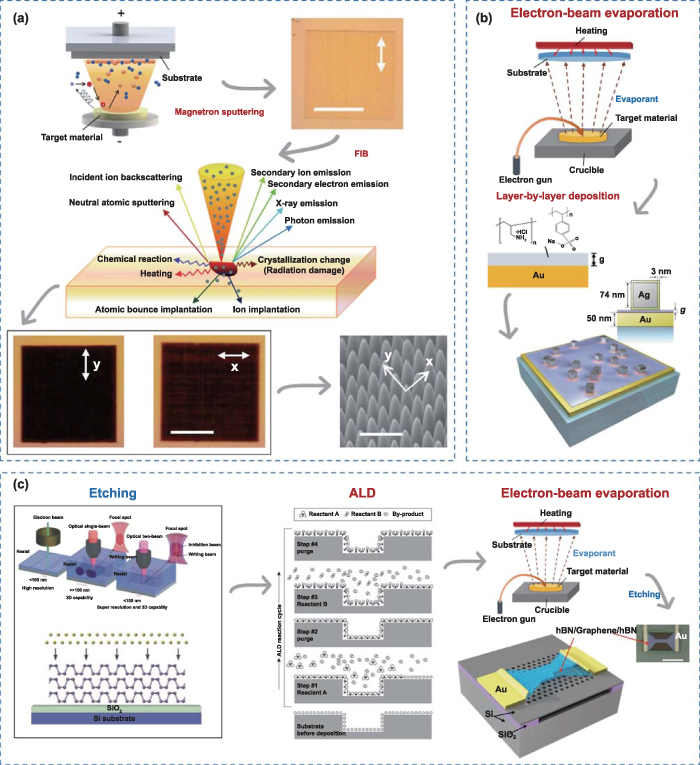
Figure 8. Specific processes for the preparation of metamaterial emitters. (a) The preparation of arrays of ultra-sharp grooves in gold [151, 155], where magnetron sputtering and FIB are used. Reproduced from [151] with permission from the Royal Society of Chemistry. Reproduced from [155], with permission from Springer Nature. (b) The preparation of controlled-reflectance surfaces with film-coupled colloidal nanoantennas [156]. Reproduced from [156], Copyright © 2012, Springer Nature Limited. The typical method used is electron beam evaporation. (c) Hot graphene electrons coupled to a photonic crystal nanocavity, prepared mainly by ALD, electron-beam Evaporation and etching methods [157–159]. Reproduced from [157]. CC BY 4.0. [158] John Wiley & Sons. Copyright © 2012 WILEY-VCH Verlag GmbH & Co. KGaA, Weinheim. Reproduced from [159]. CC BY 3.0.
Download figure:
Standard image High-resolution imageNevertheless, it is difficult for most metal-containing emitters to circumvent the problem of oxidation at high temperature. Many researchers have chosen to place tests of emitter performance under low-pressure and protective gas to demonstrate the thermal stability of the emitter [88, 130, 160]. Rinnerbauer et al used a thin coating of HfO2 with excellent stability at high temperature, as a thermal barrier and surface protection layer. However, experiments with emitters in the TPV system require a vacuum environment [133]. McSherry et al studied a tunable wavelength-selective heterostructure consisting of alternating layers of BaZr0.5Hf0.5O3 (perovskite) and MgO (rocksalt), which maintains clearly separated refractive-index-mismatched layers without interface coarsening, interdiffusion, phase change or decomposition up to 1100 °C in dry air [161]. This suggests that the problem of thermal stabilization of emitters for certain materials can be solved. It is promising to enable emitters to be spectrally selective and thermally stable in the future.
Materials for emitters of TPV systems are still being explored. Note that although most studies provide promising performance of selective emitters in the emission spectrum, it is difficult to reduce the waste heat to a low level in a real TPV device by emitters alone. Devices that work with it, such as back reflectors, can be considered.
2.3. Research on PV cells with narrow bandgap
TPV devices perform direct thermoelectric conversion via PV cells [162, 163]. The principle of TPV is similar to that of typical PV cells. The photons absorbed by the semi-conductor act on the p–n junction to form new hole–electron pairs. Under the action of the electric field built into the p–n junction, holes flow from the n-zone to the p-zone and electrons flow from the p-zone to the n-zone, and a current is formed when the circuit is turned on [164, 165].
The cell efficiency is expressed as follows [166]:
where  denotes the electrical power output,
  denotes the incident power on the cell, and the maximum electrical power generated by the PV cell is expressed as the open-circuit voltage
  , the short-circuit current
  , and the fill factor
  .
.
Wein's law gives the peak spectral wavelength as a function of the radiating surface temperature as follows:

where  is the energy peak wavelength in μm and
  is the temperature in Kelvin.
The relationship between band gap and wavelength of TPV cells can be expressed as [167]:
where  is the bandgap in eV and
  is the wavelength in μm.
Several promising narrow bandgap PV materials for TPV systems have been identified in studies as early as the beginning of the 21st century. The external quantum efficiencies of different materials can be seen in figure 9(a). External quantum efficiency (EQE) represents the proportion of electrons collected per incident photon at a given energy and is able to measure the efficiency of the cell in converting photons into electron–hole pairs [26, 168]. Figure 9(b) shows the blackbody radiation spectra and the band gaps of various PV materials for TPV operating temperatures of 1000–2000 K. Unfortunately, each of these PV materials has its own drawbacks, and none of them is perfectly suitable for large-scale TPV applications. Narrow bandgap materials like InAs, InAsSbP have low open circuit voltage and are not suitable for PV. GaSb, InGaSb such materials are used in most of the system studies because of their better usage, but they are expensive and cannot meet the economics. The electrical performance of Ge with a band gap that is not very different from them is poor. The band gap of the cheapest silicon cells, in turn, is often too high [169, 170].
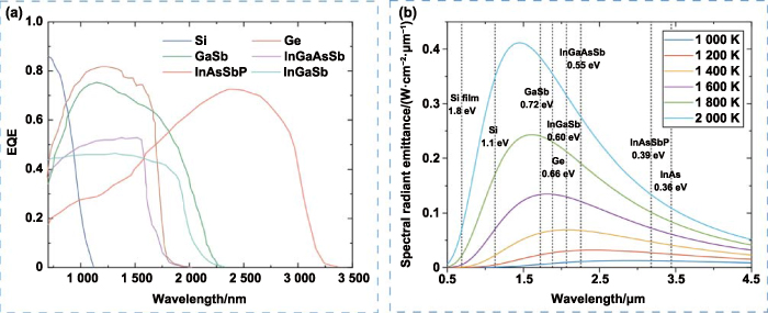
Figure 9. External quantum efficiency (EQE) and band gaps of different materials. (a) EQE of different TPV cell materials [171, 172]. (b) Blackbody radiation spectra from 1000 K to 2000 K and band gaps of common photovoltaic cell materials [167, 173].
Download figure:
Standard image High-resolution imageRepresentative research results of PV cell materials for thermal PV systems for the decade 2012–2022 are shown in table 4. Most of the initial studies were directed at individual narrow bandgap materials, making the choice of materials very limited. However, semiconductor compounds of group III (Al, Ga, In) and group V (N, P, As, Sb) elements can form high-quality crystalline films with variable bandgaps [174, 175]. In recent years, different types of PV cells for achieving high efficiency TPV systems in thermoelectric conversion have been published several times in high level journals. Omair et al calculated the optimal band gap versus back reflectance, and the TPV efficiency can reach >50% through the optimal band gap. Therefore, to achieve a TPV system with high efficiency, a combination of PV cells with back reflectors and selective emitters can be considered [176]. Current research explores a variety of combinations of the existing III–V materials that work with emitters and back-reflectors to achieve efficiencies of up to 40% [177, 178]. Additionally, air-bridge cells are involved in some TPV studies to reduce energy loss. For example, Fan et al embedded a layer of air (air bridge) in a thin film In0.53Ga0.47As cell. With an approximately 1455 K silicon carbride emitter, the absolute efficiency gained exceeds 6%, leading to a very high power conversion efficiency of more than 30% [179]. However, the physical rigidity of high efficiency TPV cells, especially using III–V compound semiconductors, further limited their widespread use. Kiani et al realized solution-processed colloidal quantum dot (CQD) solids as the active layers within TPV devices employing 0.75 eV band gap CQDs [180]. TPV cells could therefore be conformally coated to achieve better IR performance and thermal stability with CQDs. The methods commonly used in recent years to improve the TPV efficiency are shown in figures 10(a)–(c).

Figure 10. Different materials of TPV cells. (a) TPV cells made of III–V materials [177, 181]. Reproduced from [177]. CC BY 4.0. Reprinted from [181], © 2022 Elsevier Inc. (b) TPV cells with air-bridge structure [40, 179, 182]. Reprinted with permission from [40]. Copyright (2022) American Chemical Society. Reproduced from [179], Copyright © 2020, The Author(s), under exclusive license to Springer Nature Limited. Reproduced from [182]. CC BY 4.0. (c) PV cells made by solution-processing of semiconductor CQDs [183–186]. Reproduced from [183] with permission from the Royal Society of Chemistry. Reproduced from [184], with permission from Springer Nature. Reprinted with permission from [185]. Copyright (2017) American Chemical Society. [186] John Wiley & Sons. © 2020 Wiley-VCH GmbH. (d) Some typical studies of PVSCs [187, 188]. Reproduced from [187], Copyright © 2022, The Author(s), under exclusive license to Springer Nature Limited. Reproduced from [188], Copyright © 2022, The Author(s), under exclusive license to Springer Nature Limited.
Download figure:
Standard image High-resolution imageTable 4. The research of PV cells for TPV applications from 2012 to 2022.
| Research content | Structure | Advantages | Bandgap | Published year | References |
|---|---|---|---|---|---|
| Electricity generation from thermal irradiation governed by GaSb active layer | An economical device consisting of 100–200 nm emitter and 5–7 μm base | There is a universal critical base doping, Na = 1.5 × 1017 cm−3 | — | 2012 | [189] |
| A thin, flexible monocrystalline germanium (c-Ge) heterojunction solar cell | Exfoliation technology was applied to realize a thin 50 μm Ge-on-metal flexible substrate upon which a-Si:H/c-Ge heterojunction cells | η = 5.28% and record FF = 58.1% | Generation spectrum up to 1700 nm | 2013 | [190] |
| A novel zinc diffusion method for forming emitters in GaSb thermophotovoltaic cells | The p/n junctions were realized by the diffusion of zinc into the N-GaSb wafers | Suppress the formation of the high-concentration diffusion front | — | 2014 | [191] |
| 0.53 eV GaInAsSb thermophotovoltaic diode | Four device structures are studied i.e., p-on-n and n-on-p stack in its normal and inverted configuration | The relative larger efficiency enhancement in the low-temperature spectrum illumination | 0.53 eV | 2015 | [192] |
| Epitaxial single crystal GaSb thin film cells with different p–n junctions | A GaSb bulk cell fabricated by diffusing Zn into an n-GaSb substrate | The BR thickness is approximately equal to minority diffusion length to achieve the optimal IQE | — | 2016 | [193] |
| Van der Waals bilayer antimonene | Various 2D stacking types for vdW bilayer and trilayer grey antimony | The theoretical conversion efficiency is 31% | 0.62 eV | 2017 | [178] |
| Thin-film In0.53Ga0.47As-based structures with high spectral selectivity | Selectivity is enabled by short optical paths through a high-quality material fabricated using epitaxial lift-off, high-reflectance back surfaces, and optimized interference | Enable a predicted TPV efficiency above 50% (with a power output of 2.1 W·cm−2) | ∼0.74 eV | 2018 | [194] |
| GaInAsSb thermophotovoltaic cells on GaAs substrate with metamorphic buffer layer | Combining interfacial misfit (IMF) arrays with dislocation filtering layers (DFLs), for the MBE growth of GaInAsSb TPVs on GaAs substrates | Efficient dislocation suppression in the buffer region can enable GaAs substrates as a low-cost platform | — | 2019 | [195] |
| The air-bridge InGaAs TPV cell | The dielectric spacer within the thin-film cell replaced with air | TPV efficiency >30% | 0.74 eV | 2020 | [179] |
| The reduction of optical losses in GaSb-based thermophotovoltaic converters | Optimizing antireflection coatings and creating a back surface reflector on the photocell | Power conversion efficiency with W and SiC emitters by 3% and 10.4% (at T = 1750 K) | 0.73 eV | 2021 | [196] |
| Two-junction TPV cells | 1.4/1.2 eV and 1.2/1.0 eV tandem devices optimized for the 1900 °C–2400 °C emitter temperature range | TPV efficiency >40% | 1.0–1.4 eV | 2022 | [177] |
Since 2006, perovskite solar cells (PVSCs) have gradually shown potential for commercialization as an alternative to silicon cells with higher power conversion efficiency [197–200]. Typical studies of PVSCs are shown in figure 10(d). PVSCs prepared by the two-step bilayer diffusion growth process developed by Li et al have a bandgap of 1.28 eV and an open-circuit voltage of 0.865 V [201]. Zhao et al reported low bandgap (∼1.25 eV) single-junction hybrid Sn–Pb PVSCs, which can reach a maximum power conversion efficiency of 17.6% [202]. Unfortunately, the band gap of existing PVSCs does not meet the requirements of TPVs. The temperature-dependent performance of the perovskite/silicon tandem solar cells from 25 °C to 75 °C was investigated by Aydin et al. The c-Si bandgap energy (Eg ) narrows as temperature rises, while the perovskite Eg broadens [203]. It can be seen that the current relationship between the performance of PVSCs and temperature is only in a low temperature range, with no expansion to the high temperature case of TPV. PVSCs are generally compared in performance with silicon PV cells, both of which have a band gap of more than 1 eV [204–206]. Such band gaps are not applicable to TPVs. In addition, the stability issues of PVSCs limit the practical applications [207–209]. As an emerging material for PV cells, perovskite is expected to be useful in the field of TPVs after certain modifications.
Three typical processes to prepare an improved TPV cell are shown in figure 11. A variety of physical or chemical methods are used, depending on the improved structure. Structures containing thin films can be grown using methods that can grow compounds such as metal-organic vapor phase epitaxy (MOVPE) in addition to electron beam evaporation and molecular beam epitaxy (MBE). The methods used for patterning structures are photolithography, plating, etching, etc. If CQDs are involved, the process of solution processing could be generally used.
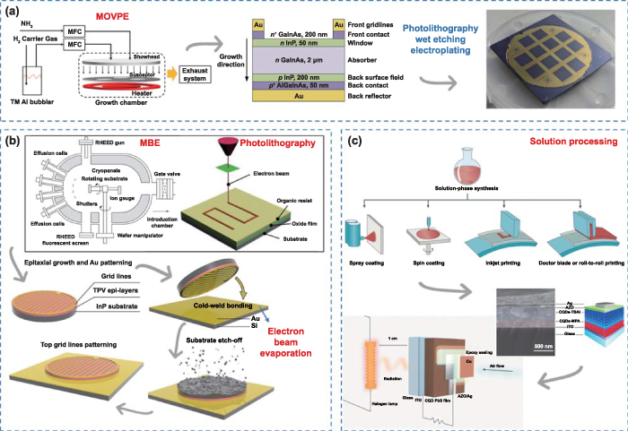
Figure 11. Some specific preparation processes for TPV cells. (a) The preparation of efficient and scalable GaInAs TPV devices [181]. Reprinted from [181], © 2022 Elsevier Inc. The growth method of GaInAs bottom cell is MOVPE [210]. Reprinted from [210], Copyright © 2021 Elsevier Inc. All rights reserved. (b) A method for preparing air-bridge thermophotovoltaic cells [179]. Reproduced from [179], Copyright © 2020, The Author(s), under exclusive license to Springer Nature Limited. The growth and cathode grid line patterning of the TPV active layers, achieved by MBE and photolithography [211, 212]. Reprinted from [211], Copyright © 2015 Elsevier 8. V. All rights reserved. Reprinted from [212], Copyright © 2015 Elsevier 8. V. All rights reserved. (c) The active layers within TPV devices are solution-processed colloidal quantum dot solids [180, 213]. Reprinted with permission from [180]. Copyright (2016) American Chemical Society. Reproduced from [213], with permission from Springer Nature.
Download figure:
Standard image High-resolution imageAdditionally, to maintain proper operation of the PV cell, TPV system designers often add heat dissipation to the back of the cell. For application-oriented, stereoscopic TPV systems often have voluminous cooling ribs or liquid-cooled piping [43, 214]. Thermal management requirements for PV cells are more demanding than for emitters, because the thermo-electric conversion properties are highly susceptible to degradation and irreversible damage when overheated.
In general, III–V materials are the most suitable choice for TPV cells in terms of performance. Although the material is expensive, it is an existing and efficient technology proven in practical applications [181, 215]. To increase the PV cell conversion efficiency, a multi-junction architecture is the choice of most studies [216–218]. How to ensure it meets the band gap requirements of TPV while also being able to maintain long time thermal stability and low cost is the future direction to explore.
3. Application analysis, calculation of industrial waste heat (IWH) recovery
3.1. Current status of waste heat utilization
Energy conversion losses account for approximately 88% of the global energy supply, of which about 50% is waste heat [219]. Referring to the definition of energy grade by Ammar et al, high grade heat is defined as heat that can be captured by industrial processes, while low grade heat is the heat that cannot be recovered in the process and is rejected to the environment [220]. Forman et al made an investigation of the waste heat distribution to estimate the global waste heat potential [9], as shown in figure 12(a). Owing to the burning of fossil fuels, industrial and transportation processes generate large amounts of high-grade waste heat. The heat source temperature of TPV system should be above 900 °C, which has a promising application in high temperature industry.

Figure 12. Data on world waste heat. (a) Sectoral shares of waste heat distribution [9]. Industrial and transportation processes generate more high-grade waste heat due to the high-temperature processes of fossil fuel combustion in both. (b) Energy demand for iron and steel by fuel in the Net Zero Scenario, 2010–2021 [221]. (c) Distribution of high-temperature waste heat in the steel industry [222]. (d) Changes in world crude steel production from 2017 to 2021, from World Steel Association [223].
Download figure:
Standard image High-resolution imageGreat potential exists for industrial activities in terms of waste heat recovery. Energy efficiency and emission reduction in the industrial sector is a decisive factor in achieving a low-carbon transition. IWH is currently underutilized despite its huge potential. In Germany, the ratio of energy to waste heat is, on average, 13% [224]. The U.S. had an energy loss of almost 61% in 2013 already [9]. In China, large coal-fired cogeneration plants alone account for more than 45% of waste heat. Exhaust gas waste heat accounts for more than 30% of the heat input, and flue gas waste heat accounts for more than 15% [225]. The high-grade waste heat recovery rate in the steel industry is above 44.4%, the medium-grade waste heat recovery rate reaches 30.2%, and the low-grade waste heat recovery rate is less than 2%. There is great waste in it [226]. Therefore, capturing large amounts of waste heat is essential to increase energy efficiency and reduce carbon emissions [48].
Global demand for steel has grown strongly in recent years. It is expected to continue to grow, driven by population and gross domestic product (GDP) growth [227–229]. As shown in figure 12(b), the energy demand for steel by fuel in the Net Zero Scenario is shown for a decade [221]. Coal accounts for the largest share of this, generating a tremendous amount of carbon emissions [5, 230, 231], while not much heat is being fully utilized. Only approximately 25% of the waste heat generated by steel mills is currently being recovered by some commercial technologies [232]. It is estimated that the use of cogeneration heat recovery systems in the steel industry could have a global power generation potential of more than 3.1 GW [38].
As can be seen in figure 12(c), steel industry produces high-temperature waste heat, which is mainly stored in the product, slag, and waste gas [222]. Among them, slag is a by-product of the steelmaking process and is discharged at a critical high temperature of about 1450 °C–1550 °C [233], carrying a large amount of high-grade thermal energy. Table 5 shows the waste heat recovery of steel industry for different processes [226]. With the exception of blast furnace slag for ironmaking and converter slag for steelmaking, where sensible heat is largely not recovered for its solid state and high temperature characteristics, there are well-established methods for recovery of high grade residual energy and heat (above 1000 °C), such as high pressure steam recovery through dry quenching, chemical energy from coke oven gas, blast furnace gas and alkaline oxygen furnace gas through gas turbine power plants, cogeneration for power or heat production, etc. However, world crude steel production has continued to show an upward trend in recent years [234], as reflected in figure 11(d). In this trend, the full utilization of waste heat becomes more urgent, and more measures are needed to consider the recovery of waste heat in all aspects. The methods described above are recovered through direct thermal conversion, while TPV systems generate electricity through thermal radiation.
Table 5. Recovery and utilization of waste heat from different processes [226].
| Process | Quantity of total (GJ·(t s)−1) | Quantity of recovery (GJ·(t s)−1) | Rate of recovery (%) |
|---|---|---|---|
| Coking | 0.93 | 0.08 | 8.2 |
| Sintering/pelletizing | 1.56 | 0.28 | 18.0 |
| Ironmaking | 8.00 | 4.62 | 57.8 |
| Steelmaking | 1.81 | 0.81 | 44.8 |
| Rolling | 1.01 | 0.28 | 27.2 |
3.2. TPV applications for waste heat in the steel industry
Although most advanced recovery technologies currently available are known to improve overall efficiency, a significant portion of the waste heat is still not recovered. In particular, waste heat is released into the surrounding environment in the form of radiation [235], thereby reducing overall energy efficiency. TPV equipment is a viable solution in this regard, converting otherwise wasted radiant energy into useful electrical energy, thereby improving energy conversion efficiency [180]. Continuous casting of hot rolled steel plates is an example of waste heat recovery through TPV. The initial temperature of these plates is approximately 1200 °C, and the temperature after cooling is below 1000 °C. During the cooling process, the PV cells can be placed on top of the hot plates, which makes it possible to form a TPV system that utilizes the steel plates as a heat source to generate electric current. This process has a potential power generation capacity of approximately 440 kW for a hot steel plate with a surface area of 50 m2 [236]. Lewis et al noted that 3.4 W·cm−2 of infrared (IR) radiant energy emitted at 1400 K (1127 °C) by a 30% blackbody with a wavelength equal to or less than 1.8 µm can be converted to electricity by the JX Crystals Inc GaSb IR sensitive TPV cells, indicating that at least 1 W·cm−2 of electric power could be generated from the wasted radiant energy in a steel mill [237]. In addition, the study by Utlu et al stated that when a cogeneration system was used for waste heat generation in the Turkish steel industry, it was calculated that the GaSb cell could generate 29.88 MJ of waste heat annually and the In0.2Ga0.8As0.18Sb0.82 cell could generate 1.076 MJ of waste heat per year [238].
The growth of energy consumption and CO2 emissions in China is attributed to the industrial sector. China is the world's largest producer and consumer of steel [239]. However, steel production is one of the largest energy sectors in China [240], accounting for 10%–15% of total energy consumption and 15%–20% of total industrial energy consumption [241]. Xuan et al compiled and projected energy consumption and CO2 emission trends for the Chinese steel industry from 2010 to 2030 [242], as shown in figure 13. Ideally, TPV devices are assembled on the high-temperature equipment involved in each process of production. Assuming that the components all operate properly at high temperatures, the waste heat radiated can be recovered by more than 40% using the high-efficiency emitters and PV cells currently under study. Assuming a total energy consumption of 110 PJ, the TPV is estimated to recover more than 10 PJ of heat under ideal conditions. With the fuller utilization of steel scrap, TPV devices can have more application space.
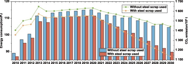
Figure 13. Historical data and future forecasts of energy consumption and CO2 emissions in the Chinese steel industry [242].
Download figure:
Standard image High-resolution imageWaste heat resources are abundant in the steel industry and exist in various processes at a wide range of temperatures and in various forms, most of which are suitable for the operation of TPV devices. Therefore, waste heat recovery has a large economic value. The application of TPV systems for waste heat recovery in the steel industry is highly promising. Since most of the steel in the world is currently manufactured with coal as the heat source, the use of TPV for waste heat recovery can reduce the amount of coal combustion and cogeneration at the same time.
4. Conclusion and outlook
This review presents representative findings from a decade of research from a system to component perspective on TPV efficiency. Furthermore, it analyzes the utilization of IWH in the world and discusses the possibility of applying TPV components in waste heat recovery of the steel industry, considering China as an example.
TPV emitters have been studied since the 1990s, initially as simple rare-earth emitters and bulk emitters. Since 2010, the focus has been on combining the functionality of filters into the emitters themselves. Selective emitters of increasingly sophisticated construction have become the main direction of research. Metamaterials can modulate the spectrum by structural design at the micro/nanoscale. Based on this feature, the overall development of selective emitters has moved toward greater precision and speed, from the traditional extensive calculations and iterations to obtain structures, to the ability to achieve rapid inverse design through methods such as machine learning.
As early as the beginning of the 21st century, narrow band gap materials such as GaSb and InGaSb have been experimentally demonstrated to enable efficient TPVs. Although they can obtain relatively high TPV efficiencies, they are insufficient to make TPVs a competitive method of thermoelectric conversion. The current mainstream research direction is to prepare PV cells with multi-junction structures using III–V group materials. Such PV cells with emitters and back reflectors can have theoretical efficiencies of >50% in simulations and >40% in real measurements. Therefore, for a TPV system, it is important to first consider an efficient and stable PV cell with an inverse design of its absorption spectrum to achieve a thermally stable selective emitter structure. The system can also reduce the heat loss by components such as back reflectors.
The combustion of fossil fuels generates a large amount of waste heat, of which industries have a promising future in waste heat recovery. Industries that generate high temperatures during production, such as the steel industry, provide the possibility for TPV systems to be applied to waste heat recovery. Contrary to traditional heat recovery methods, TPV recovers wasted radiant energy and can improve waste heat conversion efficiency.
In the background of energy conservation and emission reduction in today's world, TPV, as an emerging means of waste heat recovery, is expected to be put into industrial applications in the future. TPV is expected to be one of the effective methods for waste heat recovery in high-temperature industries, represented by the steel industry. The unused heat radiation from the industrial process is passed through a selective emitter to reach the PV cells at a specific wavelength range to generate electricity, and the rest of the heat is reflected back to raise the temperature of the heat source. However, existing researches on TPV are facing many challenges. For systems and components, the three significant challenges are stability, efficiency, and economy. The main issue of stability is the ability of the system to operate properly at temperatures above 1000 °C. Over long periods, emitters and PV cells seem to have difficulty maintaining stable performance in high temperature environments. Currently, for the thermal stabilization of emitters, researchers are focusing on the doping of materials, and for the thermal stabilization of PV cells, most researchers opt for forced cooling of the cells. From components to systems, the efficiency of TPVs is low, especially in the application of systems. Many studies have been limited to numerical calculations, others have added simple experiments, and few have been integrated into a complete and applicable system. Both emitters and PV cells for TPVs studied face the problems of difficulty in large-area preparation and high cost. Therefore, the economics of TPVs are currently not considered. The TPV waste heat recovery potentials in the relevant literature are estimated based on extremely ideal cases. It can be observed that the future trend of TPV devices is to continue to improve the efficiency of the system and to conduct practical application tests in high temperature environments to improve stability.
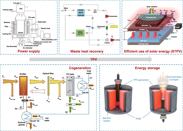
The development prospect of TPV in reducing carbon emissions is considerable. As shown in figure 14, the application of TPV technology in low carbon is not only as a power source, cogeneration, and waste heat recovery, but also solar TPV, phase change energy storage, and so on. In each of these scenarios, TPV equipment is expected to achieve higher energy efficiency and more carbon reduction through optimization of components.
Figure 14. Forecast of future directions for the application of thermophotovoltaic technology in low carbon [35, 52, 166, 243, 244]. Reprinted from [52], Crown Copyright © 2011 Published by Elsevier Ltd. All rights reserved. Reprinted from [166], Copyright © 2013 Elsevier Ltd. All rights reserved. Reprinted from [243], © 2020 Elsevier Ltd. All rights reserved. Reprinted from [244], © 2016 Elsevier Ltd. All rights reserved. Reprinted from [35], Copyright © 2016 Elsevier Ltd. All rights reserved.
Download figure:
Standard image High-resolution image
Acknowledgments
This work was supported by the National Natural Science Foundation of China (No. 52227813), China Postdoctoral Science Foundation (Nos. 2023M740905, 2023T160164), National Key Research, Development Program of China (No. 2022YFE0210200), Natural Science Foundation of Heilongjiang Province (No. LH2023E043) and the Fundamental Research Funds for the Central Universities (Nos. 2022ZFJH04, HIT.OCEF.2021023). Special thanks are given to the reviewers and people who suggest improvements of the manuscript.