

Abstract
Alkali metal anodes are among the most promising candidates for next-generation high-capacity batteries like metal–air, metal–sulphur and all-solid-state metal batteries. The underlying interfacial mechanism of dendrite formation is not yet fully understood, preventing the practical implementation of metal batteries, particularly lithium, despite decades of research. Parallelly, there is an equal significance to the other alkali metal candidates viz sodium and potassium. The major challenges of alkali metal batteries, including dendrite formation, huge volume change, and unstable solid–electrolyte interface, are highlighted. Here, we also present an overview of the recent developments toward improving the anode interfaces. Given the enormous practical potential of alkali metal anodes as next-generation battery electrodes, we discuss some advanced probing techniques that enable a more complete understanding of the complex plating/stripping mechanism. Finally, perspectives and suggestions are provided on the remaining challenges and future directions in alkali metal battery research.
Export citation and abstract BibTeX RIS

Original content from this work may be used under the terms of the Creative Commons Attribution 4.0 license. Any further distribution of this work must maintain attribution to the author(s) and the title of the work, journal citation and DOI.
1. Introduction
The discovery of alkali metals started with sodium and potassium by Humphrey Davy in the early 1800s [1]. Soon after, Arfwedson and Berzelius identified a new metal from the petalite ore (LiAlSi4O10) and named it lithium (lithos in Greek, meaning stone) [2, 3]. These alkali metals exhibited exceptional electrochemical behaviour owing to their physical and chemical properties. The element Li was extracted from lithium oxide through electrolysis by Brande and Davy in 1821 [4, 5]. Apart from their small ionic radius and low density, alkali metals such as Li, Na and K exhibit low redox potential (Li+/Li: −3.04 V vs. standard hydrogen electrode or SHE, Na+/Na: −2.71 V vs SHE and K+/K: −2.93 V vs. SHE) and high theoretical specific capacity (Li: 3861 mAh g−1, Na: 1166 mAh g−1 and K: 685 mAh g−1) that make it suitable for anode applications in rechargeable batteries [6, 7].
Early as in the 1960s, alkali metal anodes were used in primary batteries for various applications like solar-powered calculators, cardiac pacemakers etc. Li metal anode was introduced in the secondary battery system in 1976 with TiS2 as the cathode [8]. During the subsequent years, Moli Energy and Mitsui tried for the commercialization of the Li metal batteries. However, they were slowed down by the problems associated with the safety and the cycle life [9–11]. Along with lithium, molten sodium was used as an anode, with sulphur as a cathode, from the 1960s with the introduction of ceramic separators. The high operation temperature and the side reactions from the separator breakage channelled the exploration of alternates for electrolyte and active materials [12–15].
1.1. Anode candidates
Intercalation-based materials were commercialized soon after due to their increased safety and stability. The theoretical gravimetric and volumetric capacities of graphite, which is the most commonly used anode in Li-ion batteries, are 372 mAh g−1 and 735 mAh cm−3, respectively [16]. The capacity of intercalation-based anodes is approaching their theoretical value and cannot cope with the current energy demand [17–22]. Among the others, the alloying and conversion-based chalcogenide anode candidates provide a higher capacitance but are limited by their rate performance at high current rates and cycle life due to the problems caused by volume expansion (leading to pulverisation and low CE) [23]. Anodes for the Na ion batteries (SIBs) fall into many diverse regions with carbon, titanium, chalcogenides, alloying and organic materials acting as key players [24–30]. The most widely used anode in SIB is hard carbon that deliver a capacity of 300 mAh g−1 at a lower potential and for potassium is graphite. A revisit of the alkali metal anodes has recently sparked huge interest in researchers to develop batteries with high energy density [9, 31, 32].
1.2. The need for alkali metal anodes
Though lots of work can be done on the cathode side towards developing high-energy-density batteries [33], the difficulties of increasing the alkali ion transfer per transition metal and the slow progress in extending the electrochemical window make it challenging. There is huge scope for modifying the anode towards increasing the energy density [23]. While the high theoretical specific capacity and high negative redox potential of lithium make it a dominant choice in today's power sources [34], Na and K, with their low cost and abundance in the earth's crust, show promise towards the development of large-scale energy systems [34–37].
1.3. From lithium to sodium and potassium
The scarcity of the Li reserves in the earth's crust and the associated price hike of Li metal at this time of high energy demand have led us to look into alternate battery chemistries for energy storage [38, 39]. Na and K, due to their abundance and low cost, are considered promising candidates for futuristic anodes for aqueous and solid-state batteries [24, 40–46]. As Na and K do not alloy with the aluminium, replacing the copper current collector would further lead to reduced cost and improved gravimetric energy densities in these systems [47–52]. Li-ion, being a stronger Lewis acid (due to its smaller ionic size) than Na and K, has a direct effect on the de-solvation energy [47, 53]. More solvated polar molecules are needed for the stabilization of the Li ions, which increases the de-solvation energy along with the increase in the solvation shell radius. This increases the interfacial resistance during the ionic movement through the SEI, resulting in reduced ionic conductivity. In this regard, Na and K could offer better rate performances to meet high-power applications compared to Li [54, 55]. Due to the soft nature of Na and K, a smaller amount of mechanical pressure can have a huge impact on dendrite suppression. In this review, we attempt to project the main challenges associated with alkali metal anodes and discuss various strategies to mitigate the issues in-order to realize the faster implementation of solid-state alkali metal batteries.
2. Bottlenecks of metal anodes
Despite their potential to offer high energy densities, alkali metal anodes, including lithium, sodium, and potassium, suffer from several technical challenges (figure 1) that include [56–58]:
- (1)
- (2)Instability of metal electrode: Metal anodes can be unstable due to the reaction with the electrolyte, leading to the formation of solid electrolyte interphase (SEI) and degradation of the electrode. The reactivity of these materials with oxygen and water makes it difficult to handle under ambient conditions, and subsequent reaction with electrolytes upon battery assembly leads to the formation of unstable SEI [11].
- (3)Safety concerns: Using metal anodes in batteries can result in safety issues, such as thermal runaway and the risk of fire or explosion.
- (4)Limited cycling performance: Metal anodes show limited cycling performance compared to metal-ion anodes due to the formation of SEI and the degradation of the metal electrode over time. The infinite volume change due to the lack of hosts also leads to porous depositions, pulverization of active material, Coulombic efficiency loss and rupture of the SEI layer [61]. The associated problems of lack of electronic and ionic channels shorten the life span of the alkali metal batteries.
- (5)Compatibility with other battery components: Metal anodes may not be compatible with other components, such as the separator and the electrolyte, due to their highly reactive nature.

Figure 1. Schematic illustration of the major challenges in an alkali metal anode.
Download figure:
Standard image High-resolution imageDespite these challenges, researchers are actively developing new strategies to address these problems and make metal anodes viable for practical applications in batteries. Some of these efforts include the development of new electrolytes, surface treatments, and other techniques that improve the stability and safety of metal anodes.
The intensities of the hurdles vary differently within the metal anodes but are common to all of them. Alkali metals are generally found as minerals rather than metallic due to their high reactivity and low first ionisation energy (Na = 495.8 kJ mol−1). For instance, metallic sodium is so soft that it can be cut using a knife due to its weak intermetallic bonds and is generally stored in kerosene due to its reactivity. Sodium can readily react with oxygen, carbon dioxide, and moisture, whereas the latter can lead to the production of inflammable hydrogen. The high reactivity of the metal not only leads to unwanted reactions within the battery but also arouses difficulties in its processing and storage [23]. The solubility of different alkali salts, decomposition of the solvents and the presence of organic products on the anode during cycling was observed even during the 1950s [62].
2.1. Unstable SEI
The parasitic reduction reaction is initiated when the energy of the lowest unoccupied molecular orbital of the electrolyte is less than the electrochemical potential of the anode, leading the formation of the solid electrolyte interface [63]. The term solid electrolyte interface and the possible model for the same was introduced by Peled in 1979 [64]. The ideal property of the SEI includes perfect ionic conductance with quality of electronic insulation [23]. A stable SEI acts as a protective layer and prevents further decomposition of electrolytes and loss of active material. The mechanical stability and optimum thickness of the SEI can directly impact the cycle life and Coulombic efficiency.
Generally, two different models have been proposed for the SEI: Mosaic and multilayer models. In the former model, the reductive reactions are considered to simultaneously produce an interface with mixed components [65] in the multilayer model, the components are formed inhomogeneously concerning the depth of the interphase [66]. The inorganic species with low oxidation states (Li2O, Li3N, LiF, LiOH, and Li2CO3) are formed closer to the alkali metal and the organic species with higher oxidation states (ROCO2Li, ROLi, and RCOO2Li) are formed closer to the electrolyte contact [23].
While stable passivation acts as protection, its formation is more difficult in Na and K compared to that of Li due to their high reactivity. An uneven interface is formed for Na when it comes in contact with the electrolyte, far worse than the case of Li. The pits and heaves within these rough interphases formed during the battery assembly can act as further seeding sites for dendrites [67]. The higher reactivity of the K compared to the other two alkali metals makes it more difficult to form a stable passivation layer [68]. Moreover, the reactivity itself reduces the number of compatible and stable electrolytes for the K-based battery systems and a mere adoption of electrolytes from other systems is not possible [69]. The dissolution of the passivation layer can expose fresh alkali metals and lead to further electrolyte decomposition. These new sites can initiate dendrite formation as well. The Lewis acidity difference of the alkali metal ions can lead to differences in the solubility of these decomposition products [34]. The weak Coulombic interaction of Na+ with the solvate molecules has led to the dissolution of its decomposition products (sodium oxide, hydroxide and carbonates) in comparison to its Li counterparts [70].
2.2. Dendrites
One of the main reasons for the failure of commercialization of the alkali metal anodes were the safety issues. Thermal runaways, electrolyte combustion and cell explosion can be induced when the battery is short-circuited by the internal unevenly grown 'dendrites'. Non-uniform deposition of the alkali metal anodes leads to the formation of dendrites [9]. The mechanism of nucleation and the growth of the dendrites are not fully understood, even though many models have been proposed [32, 71–74].
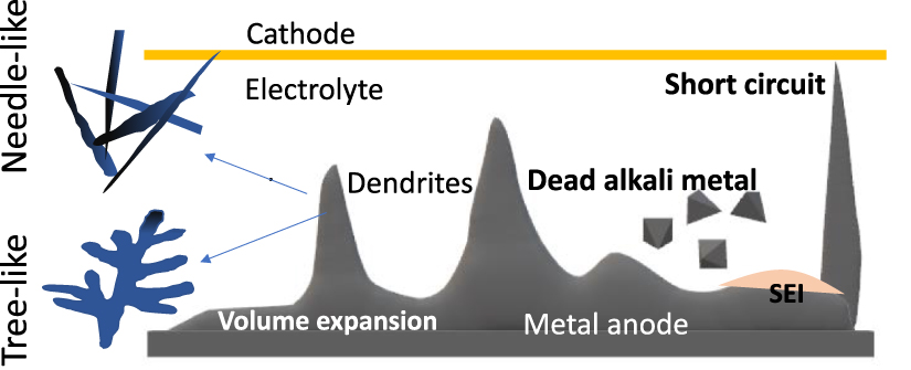
Dendrites can occur in different morphologies: needle-like, tree-like and moss-like morphologies. The needle-like dendrites are the main cause of the separator piercing as they are grown in length and diameter without any branches. In contrast, the tree-like morphologies are not common but have been modelled and studied. Both these morphologies are mainly observed during the initial cycles. Upon ageing, the moss-like morphologies are observed, which due to their high specific area and weak mechanical nature leads to the increased decomposition of electrolyte along with the formation of dead alkali metal. In most cases, the morphologies co-exist in a battery and transformation of morphologies also happens depending on the experimental conditions [23].
Different models have been proposed for forming the dendrites, and different in-situ imaging techniques have also been used to understand the process. Generally, a high local current density within the vicinity of high ionic concentration can lead to the formation of dendrites. When the concentration of the cations near the anode decays to zero, the surface inhomogeneities of the anode can lead to a variation in the local electric field, which might lead to dendritic formation. SEI, made of different components with diverse migration and surface formation energies, can form inhomogeneities at the surface, creating hotspots for dendritic formations. Different morphologies of the dendrites have been observed, among which the needle and whisker-shaped ones lead to the short circuit while the 3D moss-like structure leads to dead metals [23].
When it comes to the practical application of high areal capacity (>3 mAh cm−2) and high current density (>3 mA cm−2), a poor understanding of the dendrite formation can lead to poor cyclability [7]. High current density, high areal capacity and reduced pressure environment of the practical batteries can lead to the quick formation of dendrites. The low plasticity of the Li metal anode can in turn, produce microscopic defective sites on the surface that acts as seeds for the dendritic formations [16]. Short circuits created by the dendrites can easily happen at the high current densities, while the low current densities, due to the powdering of the Li, can lead to more formation of dead lithium [16]. The dead alkali metal formation also depends upon the dissolution of the dendrites in their corresponding electrolytes. Faster dissolution of the Na dendrites has been observed compared to the Li in LiPF6 and NaPF6-based solvents. The high chemical activity of the Na leads to an accelerated reaction with the trace amount of water within the solvents, leading to faster dissolution [67].
2.3. Dead metals
The major problem with Li metal anodes is the Coulombic efficiency rather than the dendrites [75–77]. The current advances in the high-concentration electrolytes have mitigated the failures like thermal runaways caused by the dendrites by aiding the formation of interwoven whisker-like structures which seldom pierce the separator before the failure caused by the CE. The main cause of the CE being less than 99% can be attributed to the inactive Li that can lost in the formation of continuous SEI formation or in the electrically insulating environment. Among them the electronically cut out Li has been identified as the main cause for the reduced CE which can be due to the whisker like structure of dendrites formed due to the tortuosity factor, lack of porosity and due to the heterogenous SEI [78].
Weak mechanical stability of the Na dendrites due to their larger ionic radius and reduced metallic bonding has been observed. The accelerated dissolution of the Na dendrites along with the weak mechanical stability leads to its breaking and formation of dead Na [67]. Among the alkali metals, K showcases the weakest mechanical feature with the highest reactivity [79].
2.4. Volume expansion
The lack of a host for the alkali ions, as in the case of graphite and silicon, leads to an infinite volume change and 100% depth of discharge for the alkali metals. Loss of active material through dissolution followed by the pulverisation, increase in the resistance due to the inhomogeneous porous deposition, cracking of the SEI and associated side reactions, and the overall capacity fade and loss of Coulombic efficiency are some serious problems associated with the volume expansion [23].
The alkali metal's packing density during the deposition depends on numerous factors like the morphology, cell configuration and anode structure. Theoretically, the volume change per mole of the Na and K are calculated to be twice and four times that of Li. Thus, the problems associated with the volume expansion will be elevated for Na and K compared to Li.
High-temperature Na–S batteries, zebra batteries and thin film Li batteries are some of the commercialized battery systems that employ alkali metal anodes. While the HT Na–S batteries have been utilized for grid storage, the lithium thin film batteries found its application in wearable electronics. With the success of the Li-ion batteries, Li metal anode is expected to be the earliest to commercialize.
Mechanical stress can also cause the formation of cracks in the lithium deposit, which can serve as nucleation sites for dendrite growth and increase the likelihood of short circuits. In addition, stress can cause the growth of dendrites to become more uneven and result in the formation of thicker and more irregular dendrites.
3. Factors influencing the nucleation and growth
Lithiophile theory: The crystal structure of metals is very closely related to the plating and stripping efficiency. The body-centred cubic packing of alkali metals is found to be more efficient due to the structure. Within the metals, the kinky surfaces have low thermodynamic overpotentials in comparison to the terrace surfaces [80]. Lithium has an atomic radius parameter of 76 pm and a lattice constant parameter of 0.35, which is a closer match to that of copper (face centred cubic) of 73 pm and 0.361, respectively. This similarity reduces the nucleation energy barrier during plating and stripping (gold and other expensive metals have lower energy barriers) [81].
Crystal plane orientation has a direct effect on the specific wettability of the interfaces. Cu (100) plane has been shown to exhibit better wettability for lithium, leading to a uniform nucleation and deposition in comparison to the Cu (110) and Cu (111) planes [82]. The binding energy of Cu (110) is also lower, leading to the easy and efficient deposition of lithium on the high surface energy interface.
Electronegativity, local dipole moment and the charge transfer at the conductive sites affects the nucleation of Li [83]. The electric field, Li concentration gradient and the electrostatic interaction between the ion and the electronegative site (dependent of the surface chemistry of the anode framework) drives the Li-ion to the lithiophilic site. Thermodynamically, Li nucleation leads to a decrease in free energy due to the phase transition (driving) and an increase in the surface energy due to the new interface creation (acts as a barrier). According to the classical heterogeneous nucleation theory, introducing the framework will not change the critical nucleation radius (r*), but can lower the nucleation barrier and reduce the nucleation volume needed to reach r*. Larger binding energy can render a lower Li nucleation barrier and, thus, a smaller nucleation overpotential. Binding energy is therefore proposed as a quantitative descriptor of the lipophilicity of anode framework.
3.1. Electronegativity
Acid-base theory in oxygen doping: aO-GNR (carboxylic group containing graphene nanoribbons) with an extra pair of electrons in the carboxylic functional group site is expected as an electron-rich donor that naturally acts as Lewis base sites to absorb Lewis acidic Li ions through acid-base interactions strongly. Most electronegative F doping is not good: F, O & N doping forms sigma-bonds with adjacent carbon and withdraws electrons through inductive effects. O and N atoms participate in the delocalized pi system of GNR that contributes to their negative charge states. In contrast, the filled p orbitals of the F atom form a p–pi conjugation with the carbon plane that feedbacks electrons from the F atom to carbon. As a result, the F atom is less electronegative than the N and O atoms. S, Cl, Br, due to their increased size, leads to weak interaction with Li [83].
On the other hand, in the case of boron doping, boron is electropositive, and the adjacent carbon atoms are electronegative due to the smaller electronegativity of the B atom (2.04) against the C atom (2.55).
3.2. Local dipole
Local geometrical and electronic structures of the dopant also play a vital role. Herein, the 'local dipole', is defined as the dipole formed by the doping atom and its adjacent carbon atom. A strong local dipole not only renders a strong ion-dipole force toward Li ions, but also delivers an induced dipole to the absorbed Li ions. Binding energy is found to be proportional to 'log (0.5 × electronegativity + local dipole)'. Co-doping of O and B increases the local dipole [83].
3.3. Charge transfer
Bader charge and charge density difference analyses. The correlation between binding energy and charge transfer is further probed. When charge transfer increases up to 0.9 e−, a surge of the binding energy is sparked. Therefore, a critical charge transfer around 0.9 e− is determined.
In general, the growth rate of dendrites can be reduced by decreasing the voltage applied to the battery, increasing the lithium-ion concentration in the electrolyte, or modifying the electrolyte. Ongoing research aims to understand the kinetics of lithium dendrite growth and develop strategies to control or prevent dendrite formation in lithium metal anodes. Stress is one of the factors that can affect the growth of lithium dendrites in lithium metal anodes. Dendrites are highly branched and brittle structures prone to breakage and cracking under mechanical stress. In addition, the growth of dendrites can be influenced by the formation of mechanical stress within the lithium deposit, which can result from the mismatch of thermal expansion coefficients between the lithium and the substrate.
4. Protection strategies for lithium
Numerous models, such as the space charge model, surface diffusion model, SEI-induced nucleating model and crystallography model, have been proposed for the nucleation and growth/platting of metal ions with the bulk [84–87]. The dendrite formation is mainly accounted for by the reaction of lithium metal with the organic electrolytes and the inhomogeneous SEI layer formation. Inhomogeneous SEI films cause non-uniform Li+ ion flux and uneven Li plating/stripping behaviours, resulting in Li dendrite growth. As shown in figure 2, protective coatings are one of the reliable techniques which can improve the Li-anode performance by curtailing the reactions happening at the interface and forming isolated Li that leads to poor Coulombic efficiency. The protective coatings enable uniform ion transport and, consequently, homogenous Li metal deposition, which can prevent Li dendrite formation [88]. These protective coatings can be considered artificial SEI layers, which minimize the side reaction between Li and the electrolyte [89]. Researchers have tried various inorganic ceramics, organic polymers and their hybrids as artificial SEI layers. The protective coatings must be ion-conducting so that Li ions can pass through it and allow it to deposit beneath the coating. A good coating should possess good mechanical strength and reduced side reaction. A shear modulus above 4.25 GPa indicates good mechanical strength [90].

Figure 2. (a) The continuous formation of inactive Li is the direct cause of low Coulombic efficiency (CE), safety hazards, and cell expansion in Li-metal batteries. Li whiskers with large tortuosity and heterogeneous solid electrolyte interphase (SEI) will facilitate the inactive Li formation and cause a series of problems. Conversely, if the deposited Li possesses a chunky morphology with minimal tortuosity and homogeneous SEI, inactive Li formation will be significantly reduced, resulting in high CE. Reprinted from [78], Copyright (2019), with permission from Elsevier. Role of (b) pressure and mechanical strength, and (c) selective permeation in lithium anode to improve the performance.
Download figure:
Standard image High-resolution imageThe side reaction at the Li metal electrolyte interface can be inhibited or controlled by selectively conducting Li-ions and not the solvent molecules anions through the artificial SEI (figure 2). Various techniques like direct coating (roll coating, doctor blade casting coating, spin coating, planetary milling technique, the dipping method), CVD, PVD, etc, have been explored for fabricating different types of SEI films [91].
4.1. Inorganic coatings
High shear modulus and ionic conductivity enable the inorganic coating to suppress dendrite growth and allow its electrochemical reactions at the electrodes to occur [89, 92].
- The fabrication methods of inorganic coating can readily achieve low thickness and high homogeneity to improve interfacial stability without severe damage to the electrode effectively.
- Inadequate thickness or compositional control of the coatings may lead to compromised SEI homogeneity. More importantly, given the limited Li-ion conductivity or poor flexibility of the coating materials, the cracking of the artificial SEI layers during cycling will induce even greater inhomogeneity on the Li metal surface, exacerbating dendrite growth and side reactions. Electrolyte degradation owing to the highly reactive Li metal has also been a serious concern [93–96].
Various coatings of alumina [97], fluorinated graphene [98–100], carbon [101–103], nanodiamonds [104], polyacetylene [105], tetraethoxysilane [106], lithium phosphorus oxynitride [107] have been reported as an effective anode interface layer. The thickness of amorphous carbon coating affects the electrochemical performances from two aspects; the thick coating can prevent the formation of dendritic lithium very efficiently but lead to a large resistance of Li transfer [108, 109]. Achieving good performance of Li/C electrodes needs a moderate thickness of a-C coating [110].
Belov et al [105] reported Cu3N-polymer composite coating, with Cu3N nanoparticles dispersed in tetrahydrofuran with styrene butadiene rubber (SBR). The protective film on the surface of the lithium anode was prepared by drop casting. Cu3N provided mechanical strength to suppress Li dendrite propagation while the SBR maintained the film's integrity without cracking during battery cycling. The film showed good mechanical strength and flexibility accounted for by the synergistic action of Cu3N and SBR.
Zheng et al reported a flexible, interconnected, hollow amorphous carbon nanosphere coating as an interfacial layer, which, due to its chemical stability when in contact with lithium, resulted in a Young's modulus of ∼200 GPa, and a minimal contribution to the impedance to charge transfer [111]. The hollow nanosphere layer was fabricated using a templated-assisted approach. Initially, polystyrene nanoparticles are deposited onto the Cu substrate followed by the deposition of amorphous carbon via flash-evaporation of carbon, and finally the polystyrene template by thermal decomposition. Coulombic efficiency of ∼99% was achieved for more than 150 cycles. Umeda et al demonstrated the formation of an electrochemically stable mesoporous SiO2 film over lithium electrodes by reacting with lithium, stabilizing the surface [106]. The electrode was prepared by dipping freshly polished lithium in tetraethoxysilane for 5 min, which was wiped and directly used in test cells. It was demonstrated that after some 100 cycles of lithium plating and stripping, the impedance of the surface remains constant. Liu et al [104] have developed a double-layer nanodiamond thin film interface by microwave-plasma chemical vapour deposition which exhibits excellent stability against lithium, high mechanical strength (Young's modulus over 200 GPa) and low electrical conductivity. A Coulombic efficiency of >99.4% at 1 mA cm−2 was achieved.
A spin-coated porous Al2O3 layer as a protective layer for a lithium–sulphur battery has been shown to improve the capacity retention of Li–S battery from 50% to 70% by spin coating slurry of Al2O3:PVDF (70:30) mixture over lithium metal anode. This technique is relatively simpler and cheaper [97]. Kozen et al reported atomic layer deposition (ALD) of Al2O3 with 14 nm thickness that shielded the Li surface from corrosion owing to exposure to environment, sulphur, and electrolyte. Using Li–S battery cells as a test system, thus modified anodes were shown to retain more capacity for up to 100 cycles compared to the cells assembled with bare Li metal anodes [112]. Li3PO4 is another material reported as an interphase layer for Li metal anode with excellent stability (0–4.7 V vs. Li/Li+) and low electrical conductivity (10−10 S cm−1). The amorphous coating generated by magnetic sputtering stabilizes the interface between the lithium metal and the electrolyte. In an alternate approach, polypyrrole was used as the coating material for the Li powder anode for lithium-sulphur batteries. This technique was user-friendly, had a high preparation efficiency, and prevented the chemical interaction between the lithium anode and the lithium polysulfide dissolved in the liquid electrolyte [113].
A biomimetic design of artificial SEI films for Li batteries with high energy density and capacity has been developed by Jiang et al It involves rationally integrating ClO4− decorated UiO-66 MOF and flexible lithiated Nafion binder (Li-Nafion) on the surface of Li metal anodes using the drop-casting method, as shown in figures 3(a) and (b). The film demonstrates excellent single-ion conductivity and remarkable mechanical strength [114].

Figure 3. A few examples of lithium metal modification approaches discussed in this review. (a), (b) Schematic illustrations for the bionic design and rational synthesis of UiO-66-ClO4 and the artificial UCLN film on the Li metal surface [114]. John Wiley & Sons. © 2020 Wiley-VCH GmbH. (c) Li plating behaviour in Li metal anodes protected by artificial SEI layers, including conventional organic–inorganic composite layers based on solid inorganic nanofillers, and (d) all-organic composite layers based on rigid and porous xPCMS-g-PEGMA nanofillers prepared by grafting flexible Li+ conductive PEGMA brushes from xPCMS nanospheres, followed by compositing with single-ion-conductive LN. Reproduced from [115], with permission from Springer Nature. (e) Schematic illustration of the mechanism of Li ions' intercalation into perovskite lattice, the formation of perovskite-alloy gradient Li ion conductor and the deposition process. (f) Hypothetical migration pathway of Li ion and corresponding potential energy surface highlighting the initial state, peak state and final state in a period. (g) Cyclic voltammetry comparison of the cells using MASnCl3-coated, MAPbCl3-coated or bare substrate as the working electrode, and the lithium as the counter and reference electrode with the sweep rate of 1 mV s−1. Reproduced from [116]. CC BY 4.0. Schematic illustration of the fabrication process for the [LiNBH]n layer and its effects toward stabilizing Li metal anodes. (h) The fabrication process for the [LiNBH]n layer on the surface of Li electrodes via an in-situ dehydrogenation-induced polymerisation reaction; (i) schematic illustration of the Li deposition on a Li metal anode under the protection of a [LiNBH]n layer, and (j) the Li deposition on a bare Li metal anode. Reproduced [117] John Wiley & Sons. © 2020 WILEY-VCH Verlag GmbH & Co. KGaA, Weinheim.
Download figure:
Standard image High-resolution imageLi et al developed a robust all-organic artificial interphase as seen in figures 3(c) and (d) by incorporating porous polymer-based molecular brushes poly(oligo(ethylene glycol) methyl ether methacrylate)-grafted, hyper crosslinked poly(4‐chloromethylstyrene) nanospheres into a lithiated Nafion polymer matrix, and were able to achieve stable cycling at a current density of 10 mA cm−2 for over 100 h [115].
In another work, a solid electrolyte interfacial layer is introduced as a gradient thin film consisting of perovskite framework on the top surface to isolate the liquid electrolyte and underneath Li–M alloy layer to induce the homogeneous deposition of Li metal (figures 3(e)–(g)). Based on the intrinsic feature of metal chloride perovskite, a fast Li ion transport gradient layer model was proposed to illustrate the shielding mechanism of perovskite thin film for the dense deposition of Li metal.
Wang et al [117] reported an artificial SEI layer formed of crosslinked and self-reinforced [LiNBH]n chains fabricated in situ on the surfaces of Li metal anodes by the self-polymerisation of lithium amido borane, which was synthesized in situ dehydrogenation reaction between Li metal and ammonia borane as shown in figures 3(h)–(j). With the [LiNBH]n layer, the Li metal anode exhibited stable cycling at a 3 mA cm−2 for more than 700 h. Another group describes a dendrite-free Li composite anode with little volume change made of mechanically rolled and folded lithiophilic MoN nanosheets and 3D interpenetrating Li nanosheets. The planar Li plating caused by the conductive 2D MoN nanosheets' tiny lattice misfit with Li and excellent lithiophilic affinity inhibits dendritic formation in the perpendicular direction. In order to reduce volume change during cycling, the MoN nanosheets interlaced framework provides an abundance of Li accommodation sites, while the horizontally plated Li fills the nanoscale gaps between the MoN nanosheets [118].
In addition to the classifications cited, we have many approaches that use additives like F, S and N-containing solvents in the electrolyte that can modify the SEI of the metal battery and promote the stability [119–125]. In an unconventional approach, very recently, a salt-philic, solvent-phobic polymer coating for Li metal electrodes was employed as a metal protection strategy [126]. The coating selectively transported the salt over solvent and thus promoted a salt-derived SEI formation thereby offering long-term cycling stability.
4.2. 3D framework
This section details the use of 3D frameworks or scaffolds to accommodate and distribute alkali metal ions uniformly in the empty volume of the porous framework in order to reduce the local current density and minimizes the formation of dendrite. It is well known that additives such as LiNO3, FEC etc, have been introduced as additives in LIB electrolytes to reduce the interface issues associated with lithium metal overlooking the issues associated with volume expansion.
Further, the continuous consumption of liquid electrolytes upon cycling hampers the use of additives as a sustainable solution for batteries that require long-term cycling. On the other hand, solid-state electrolyte is a possible solution, but the limited ionic conductivity together with issues such as large interfacial impedance impedes their practical use in batteries. A consolidated summary of different materials used as inorganic modifiers and their fabrication route is detailed in figure 4.

Figure 4. Summary of materials employed as inorganic coatings for current collector modification and their preparation procedure [47, 52, 61, 127–144].
Download figure:
Standard image High-resolution image4.3. Metallic current collectors
In order to ensure the efficient exchange of Li ions across the electrolyte and anode, the ion flux and the sluggish kinetics of the current collector surface play a crucial role. Current collector modification is, therefore, an area of interest for metal anode research to date [145–151]. A high crystalline mismatch between the metallic anode and the chosen 3D substrate leads to an increased overpotential.
In order to reduce the nucleation overpotential, the common practice is to opt for metallic substrates with BCC lattice structure similar to that of alkali metal anode. In the case of lithium metal batteries, interestingly, lithium also deposits on lithiophilic substrates, which tend to dissolve lithium partially or form an alloy with Li, like gold, even though they have an FCC lattice. Cu is among the least favourable substrates due to its reduced Li solubility and FCC structure [127, 138, 152]. Dealloying from Cu–Zn alloy has been reported using various metals, including chemical treatment [133], and vacuum distillation (due to the reduced vapour pressure of Zn) [132]. Chemical treatment of copper foil with ammonia converts them to hydroxide and is further reduced to bundles of copper fibres of submicron diameter roughly perpendicular to the foil [129]. The 3D Cu porous skeleton is obtained by electrodeposition with control over the surface pore size and thickness by tuning the solution conc, time, and surfactants added [138].
The pore size of the 3D current collector is another important point of consideration [129, 153].
When considering lithium as an example, the smaller pores cannot provide enough Li nucleation sites and fail in confining the lithium dendrite growth, subsequently leading to more deposition in the outer surface. On the other hand, very large pores, as in commercial copper foam, lead to poor electrical contact and insufficient support for the deposited lithium, leading to the increased formation of dead lithium [133]. Porous metal current collectors (figure 5) are still under consideration for large-scale applications [150]. In another work, 35 µm thick commercial copper foil is processed by a pulsed laser micro-processing system, leading to an in-situ decomposition of bulk copper into nanoparticles with a dense thin oxide coating which acts as lithiophilic nucleation sites. By precisely tuning the pore volume and depth by adjusting the laser parameters, the lithium volume expansion can be accommodated [137]. Atomic layer deposition is also a common surface modification strategy for the fabrication of 3D dendrite-ee metal anodes [154, 155]. These current collectors play a pivotal role in anode-less batteries as well.

Figure 5. (a) Design and (b) fabrication strategies of porous metal current collectors (PMCCs). (c) Summary of different top-down and bottom-up strategies for the fabrication of PMCCs. Reproduced from [150]. CC BY 4.0. © 2022 The Authors. Advanced Science published by Wiley-VCH GmbH.
Download figure:
Standard image High-resolution image4.4. Carbon and its composites as current collectors
When looking at the feasibility of carbon-based current collectors, materials such as carbon nanotubes (CNTs) and carbon felt and cloth are widely explored. One easy, scalable way to synthesize CNT over Ni foam is by exposing it to an alcohol lamp where the non-fully burned carbon species acts as the source and exposure to the air oxidizes the surface of freshly prepared CNT. The ketonic species in the CNT with lone pair act as electron rich donors with filled p-orbital acting as strong active sites for Li adsorption and act as current collectors [131].
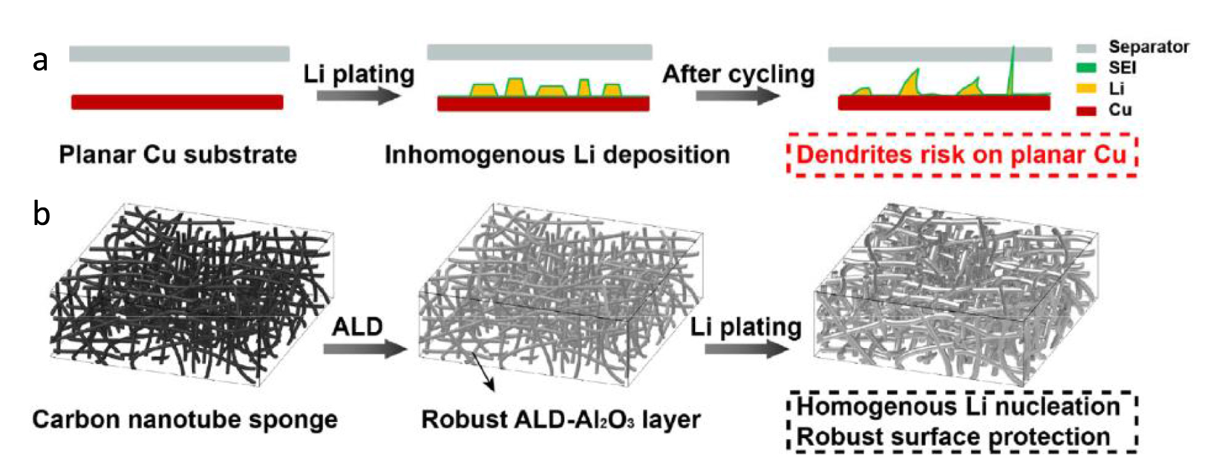
In an alternate approach, vertically aligned CNTs over graphene (GCNTs) anchored by PVDF was synthesized using the CVD technique. The low density of the GCNTs, aligned CNTs (non-tortuosity) and a uniform conductive skeleton (due to anchoring of graphene and CNTs) leads to Li host without conductive additive providing a 3351 mAh g−1 capacity with negligible contribution from the host. The high surface area leads to a reduced local current density which in turn leads to a low rate of Li-ion reduction to Li metal over GCNTs without exceeding the diffusion limit of Li-ion from the electrolyte into the pores [130]. In another work, CNTs were decorated with Al2O3 via ALD and employed as 3D current collector as shown in figure 6 [156]. The modified 3D electrode display a dendrite-free morphology and exhibited stable voltage profiles in an organic carbonate electrolyte, thus demonstrating electrochemical stability superior to that of planar copper current collectors.

Figure 6. Schematic illustration of the Li deposition process on planar Cu and 3D ALD-CNTS substrates. (a) Inhomogeneous Li deposition resulted in the formation of Li dendrites, which punctured the separator after repeated cycles. (b) A high-specific-surface-area CNTS network with a robust Al2O3 layer on the surface ensures homogenous Li nucleation during the Li plating process and forms a stable, dendrite-free Li metal anode. Reproduced from [156], with permission from Springer Nature.
Download figure:
Standard image High-resolution image5. Potassium anode protection strategies protection strategies for sodium
5.1. Inorganic coating for sodium metal anodes
Like lithium metal protection, inorganic coating is a viable option for preventing dendrites and increasing the cycle life of sodium metal anode. The low melting point and extra sensitivity of sodium metal make it difficult to form protective coatings on them. Even within these restrictions, different inorganic coatings on sodium have been reported with materials like Na3P, NaBr, NaI, NaF, etc. Sodium-based alloys come in handy with high ionic conductivity attributed to rich open ionic channels, ensuring a uniform deposition.
Additives like SbF3 in the electrolyte have been shown to form Na–Sb alloy through an in-situ reaction with the sodium metal. Fang et al studied the formation of an in-situ bilayer on the sodium metal, with adamant Na–Sb as the inner layer and a compact NaF-rich SEI on the outer layer. While the former reduced the diffusion barrier of sodium ions, maintaining a smooth surface, the latter enhanced the stability of the interface. The synergetic effect of the bilayer leads to enhanced cycling stability, superior rate capability and high-capacity retention [157].
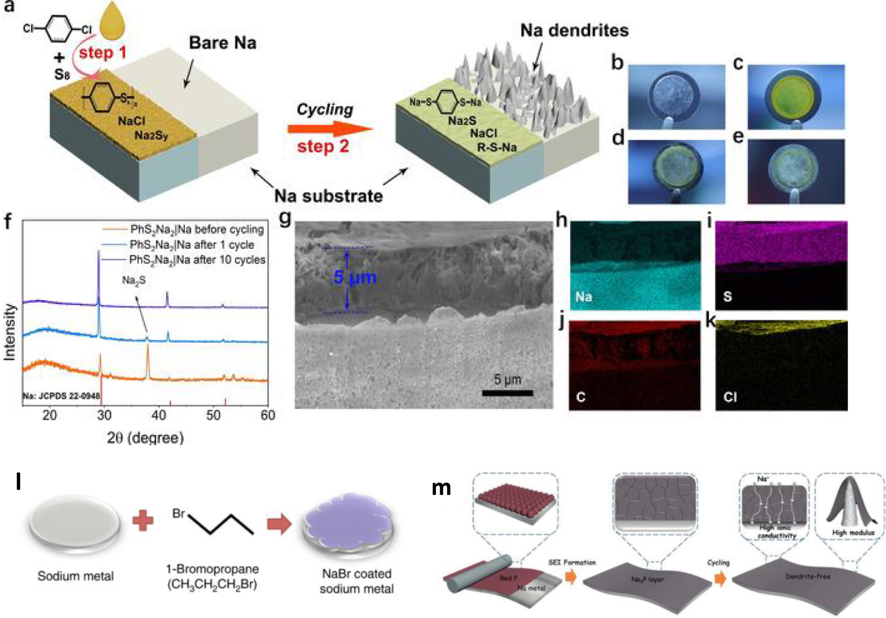
Functional groups within the protective layer can also be tuned to improve the anode performance. A sodium benzenedithiolate (PhS2Na2) rich protective layer on sodium metal, formed through a two-step process, (figure 7) was studied by Zhu et al [158]. The facile and scalable synthesis approach starts with a chemical reaction of S8 with para-dichlorobenzene and sodium as catalysts to form polyphenylene sulphides. The intermediate product converts to stable PhS2Na2 coating during the first few electrochemical cycles. The protective layer exhibits reduced interfacial transport resistance compared to pristine sodium and boosted Na+ kinetics attributed to the Ph–S–Na functional groups present in the layer. A stable cycling without dendrite formation and low overpotential were observed for symmetric and full cells with the coated sodium anode [158].

Figure 7. (a) Diagram for the fabrication of a sodium benzenedithiolate (PhS2Na2)-rich protection layer on sodium metal foil. (b)–(e) Optical photographs of (b) bare Na electrode, (c) PhS2Na2-protected Na electrode before cycling, after (d) 10 cycles, and (e) 80 cycles. (f) XRD patterns of sodium foils before, after 1 cycle, and after 10 cycles. (g) SEM image of the protected sodium foil and (h)–(k) corresponding mapping images [158]. John Wiley & Sons. © 2020 Wiley-VCH Verlag GmbH & Co. KGaA, Weinheim. (l) Schematic showing the procedure used to coat Na with NaBr. Reproduced from [159]. CC BY 4.0. (m) Schematic illustration of Na3P protecting layer on regulating Na+ plating/striping [160]. John Wiley & Sons. © 2020 Wiley-VCH GmbH.
Download figure:
Standard image High-resolution imageDue to the low surface diffusion barrier, large band gap and robust mechanical properties, NaBr has been explored as a protective coating for sodium metal [159]. The coating was shown to be effective in preventing dendrites and unwanted electrochemical reactions. While NaBr has a low surface diffusion barrier, it suffers from low diffusion kinetics due to the bulk diffusion barrier. Luo et al combined both properties through a hybrid artificial SEI composed of nano-crystalline NaBr and Na3P composites. The coating was formed through a spontaneous reaction of phosphorous tribromide with sodium metal, and subsequent sodium plating was observed to form a smooth columnar structure without dendrite formations. Enhanced cycling stability and capacity retention were observed for full and symmetric cell studies [161].
While in-situ formation might have a drawback of structural reconstruction, ex-situ-controlled formation of Na3P layer was explored by Shi et al on both sodium and Potassium metal anode. A simple rolling of ground red phosphorous on the metal leads to the formation of mechanically stable and ionically conducting coatings [160]. NaF offers a high Young's modulus (31.4 GPa), large surface energy and good electrochemical stability, making them a potential coating candidate for preventing dendrites in sodium metal anode. A heterogenous coating layer with NaF and cobalt nanoparticles was formed through a conversion reaction between sodium and CoF2. The embedded cobalt nanoparticles with defective carbon coating enhanced the sodiophilicity and improved the Na+ conductivity. Interestingly, the NaF provided three times higher Young's modulus (7.1 GPa) compared to the bare sodium metal preventing dendrites [162].
Al2O3 is also explored as an efficient protective coating to limit the dendrite formation in sodium, similar to lithium. A glovebox-integrated ALD technique and plasma-enhanced ALD by Luo et al for Al2O3 coatings [163]. Considering the low melting point of Na, the ALD technique has a low reaction temperature, and a high ionic conducting NaAlOx formation also occurs during the electrochemical cycling with the Al2O3 coating. The coated sodium exhibits a reduced lower initial overpotential, which remains stable during the cycling for symmetric cells. An optimized thickness of 25 cycles was studied to minimize moss-like dendrites and form smooth islands of sodium even during high current densities [164]. Molecular layer deposition has also been explored for the formation of inorganic-organic alucone protective layer [165]. Other coating techniques include the use of chemical vapour deposition for the formation of multilayer graphene and transferring over the sodium metal [166]. The cycling stability of sodium metal anode was shown to have greatly improved with an optimized graphene coating of 5 nm thickness.
Inorganic coatings are shown to be more efficient and better strategy compared to current collector modifications to achieve prolonged cycling life of sodium metal anodes. While most of the coatings are made through in-situ reactions, ex-situ formation of uniform coatings is still expensive and less explored. Incorporating mechanical stability and, at the same time, sodiophilic properties to the coating layers are the key to future stable metal anodes.
5.2. 3D host for sodium metal anode
The volume change of sodium during the deposition is twice that of lithium, and 3D host with a high surface area can be an effective method for longer cycling. The large surface area and uniform surface structures ensure an even electric field for better sodium metal anode depositions. The 3D metallic current collectors have been adopted for sodium, and as discussed in the previous section, copper has been chosen as a prospective material. One step dealloying of Cu–Zn alloy (Cu0.7Zn0.3) leads to forming a porous copper skeleton with high surface area, resulting in uniform deposition of sodium during plating [167]. Copper nanowire formation on 3D copper foam results in further increase in surface area and nucleation sites [168].
Unlike lithium, sodium does not react with aluminium, and the possibility of utilizing the latter as a lightweight and cheap alternative to copper current collectors has also been studied. The formation of 3D zinc nanofiber on an aluminium current collector through simple magnetron sputtering was studied. Low nucleation overpotential and small polarization voltage were achieved due to the high surface area with the in-situ formed sodiophilic NaZn13 [169].
The morphology of sodium metal deposition is strongly related to the initial nucleation and its uniformity. Sodiophilic metal inclusion in the 3D host has been explored as an advantageous technique for homogeneous nucleation, and thereby ensuring a high Coulombic efficiency. The 3D nanostructured porous carbon particle containing carbon-shell-coated Fe nanoparticles was formed though carbonization of colloidal block polymer solution. A 3D hierarchical structure with ordered open channels leads to a high CE of 99.6% at 10 mA cm−2 and 10 mAh cm−2 [170].
Carbonization of electrospun PMMA over antimony-containing carbon fibre has been performed by Li et al and studied as 3D host for sodium metal anode [171]. The PMMA generates lotus root-like channels within the structure enabling uniform deposition, and also induces N and O functional groups in the carbon structure. A horizontal growth of sodium was observed during deposition, which is attributed to the gradient sodiophilicty within the 3D framework.
The 3D printing technique has recently been explored to synthesize hosts with embedded sodiophilic metals. Wang et al produced 3D Au/rGO using 3D printing followed by freeze drying and subsequent annealing. The host showcased remarkable cycle life (1200 h at 5 mAh cm−2, 5 mA cm−2) at high current density and capacity. The technique is reported to have several advantages, such as being lightweight, the flexibility in tuning the thickness, periodicity in the microlattices [172].
Sophisticated top-down synthesis is required for the metal-embedded 3D sodium hosts, which acts as a barrier for large-scale production. Commercially viable materials have also been studied as candidates for sodium metal hosts. For instance, 3D carbon felt is used as a host where the sodium is inserted using a commercially scalable melt infusion strategy [143]. This flexibility of the felt makes it versatile, and can be used in different battery systems (cylindrical cells, pouch cells etc). Several factors including additional room to accommodate the sodium, a uniform Na+ flux, and associated lowered current density, lead to better performance in terms of high current density (5 mA cm−2) cycling. The low cost of the host further favours future commercialization. An alternate method through electrochemical plating inside carbon felt has also been explored [173].
While more materials are studied as potential hosts for sodium metal anode, the cost, availability and commercialization aspect should be considered. Incorporating sodiophilic metals in the 3D host is an interesting strategy, however, scalable methods with cheaper alternatives should be the priority for future research in this area.
6. Potassium anode protection strategies
Compared with lithium and sodium, the implication of potassium metal batteries is quite challenging due to the highly reactive nature of potassium metal and the fragile nature of SEI formed on potassium/electrolyte interface. The SEI is so much unstable that it could lead to uneven reflux of potassium ions and aggravate dendrite formation. The strategies employed to mitigate the aforementioned issues are very much in line with the other alkali metal counterparts. This includes 3D hosts as current collectors, inorganic protective coatings, carbon-based coating etc [174–176].
Though not much work on K anode is projected, materials such as oxides, carbon and emerging materials like Mxenes have been of interest as protective coatings (figure 8) [177–179]. Ding et al have reported a novel approach to protect metal anodes, particularly for potassium metal anodes. As shown in figures 8(a)–(e), they developed a metal electrode skin, which entails an artificial film made of fluorinated graphene oxide, which serves as the foremost barrier. At the molecular level, fluorine will be released and form an in-situ SEI, thereby manifesting a second protection 'skin' for the metal anode [180].

Figure 8. (a) The summarized capacity–voltage plots of different anode materials. (b) Schematic illustration of electrodeposition behaviours of K and K@MES. (c) Schematic diagram of human skin structure and surface. (d) Schematic diagram of MES structure and surface. (e) SEM images of K@MES and TEM images of enhanced SEI. Reproduced from [180]. CC BY 4.0. (f) Synthetic route of MSCNFs and the corresponding composite K anode. Reproduced from [181]. CC BY 4.0. Establishment of liquid–liquid anode–electrolyte interface. Photos of a liquid K–Na drop on (g) Celgard and (h) glass fibre membranes containing an organic liquid electrolyte at room temperature. Schematics of a cell with a liquid K–Na drop (i) not absorbed and (j) absorbed by a porous membrane. (k) Photos of liquid K–Na alloy being absorbed in a carbon paper strip at 420 °C after immersion of the end of the strip in the liquid alloy [182]. John Wiley & Sons. © 2016 WILEY-VCH Verlag GmbH & Co. KGaA, Weinheim.
Download figure:
Standard image High-resolution imageRecently, Goodenough's team proposed a K–Na alloy (KNA) anode that can remain liquid down to a low temperature of −12.6 °C, which showed a stable plating/stripping behaviour at a low current density of 0.4 mA cm–2 for 2800 h [182]. Later, a 'quasi-liquid' KNA anode formulation was obtained by introducing only 3.5 wt% of Na into K to reduce the fluidity without compromising performance [183].
7. Advanced characterisation techniques
Metal anode samples are highly reactive and air-sensitive, making reliable and reproducible characterization difficult and requiring special precautions. Most importantly, samples must be shielded from undefined changes caused by reaction with the gas phase during transport to the analysis chamber. As a result, the transfer of samples must be carried out without coming into contact with the surrounding air atmosphere. However, unwanted reactions are not restricted to just the transfer of samples and can also take place within the analysis instruments themselves.
With these challenges, battery researchers have been looking for new and improved characterisation techniques that could shed new light on the interphase phenomena. To evaluate and quantify the extent of the improvement in the anode properties and stabilisation, advanced characterisation techniques are required (figure 9). It is worth mentioning that there are numerous sophisticated imaging techniques that can monitor the evolution of the electrode interface [184–189]. However, such techniques are available in pockets and not accessible by all. The following section summarizes the main advanced characterisation techniques, that can be employed to study the electrode/electrolyte interface.

Figure 9. Schematic representations of the advances in operando techniques.
Download figure:
Standard image High-resolution image7.1. ToF-SIMS depth profiling
Although a routine XPS depth profiling could identify the constituent elements, and qualitative depth distribution of the passivation layer on the lithium samples, the lateral and depth resolutions of XPS analyses are rather low [190–192]. In addition, the sensitivity towards lithium is low and hydrogen cannot be detected at all. ToF-SIMS depth profiling can complement the XPS results with higher lateral resolution and quantitative depth information, even if ToF-SIMS results are not inherently compound-specific. Therefore, a group led by Henss applied ToF-SIMS to take advantage of its higher sensitivity, as well as of its superior lateral and depth resolution, to get more information about the three-dimensional distribution of the different compounds [193, 194]. Due to matrix effects, the ToF-SIMS results are only semiquantitative and not inherently compound-specific. Machine learning assisted logistic regression approaches are employed to ease the analyses process [195]. Through this approach, researchers were able to trace and identify different lithium compounds that are expected to appear on lithium metal anodes, namely, Li2CO3, Li2O, Li3N, LiH, and LiOH and qualitatively identify compounds on the lithium metal.
7.2. Operando microscopy
The evolution of electrode morphology is observed through operando high-resolution video capture and is directly correlated to the voltage traces. Further, in order to get an in-depth understanding of the electrochemical processes occurring on the electrode surfaces, to monitor the lithium platting and dissolution associated voltage polarization, a continuum-scale numerical model is developed. This technique is used to relate electrode morphology and compare electrochemical kinetics to the cell voltage [196]. When carrying out platting dissolution measurements and correlating the voltage profile shapes and EIS, there have been many instances wherein it is difficult to differentiate between soft shorts [197]. A clear picture of the electrode during cycling is evident from this operando video microscopy. This helps give insights on the dendrite evolution. Figures 10(a)–(e) shows a quartz cell design used for monitoring the dendrites [198]. The technique helps avoid the process of disassembling and drying, leading to significant changes in the surface morphology and damage to the anode.

Figure 10. (a) Schematic illustration of the quartz cell device with transparent windows and rectangle empty space inside as the cell housing, in which a sandwich structure of lithium metal, separator and stainless steel substrate was assembled. The fabricated cell was put on the stage of optical spectroscopy with transparent window facing to the lens for in-situ characterization. (b), (c) A series of dark-field optical microscope images of the cell's cross-section (b)–(c), optical images versus increasing lithium deposition time), revealing the growing process of lithium dendrites at 5 mA cm−2 on the stainless steel substrate using electrolyte with the addition of both Li2S8 and LiNO3. (d), (e) A series of dark-field optical microscope images of the cell's cross-section (d), (e), optical images versus increasing lithium deposition time), showing the growing process of lithium dendrites using electrolyte with the addition of only LiNO3 at the same current density as (b), (c). Scale bar, 100 μm. Reproduced from [198], with permission from Springer Nature. (f) The THz signal of the PET substrate, with and without the presence of the silicon electrode (THz beam reflections depicted in blue and orange respectively). The THz transients are separated by 12 ps. The π-phase reversal is attributed to reflection from high to low refractive index, as predicted by the Fresnel equations. Note that only the signal reflected from the electrode (back surface reflection) changes with cycling conditions and holds the SEI information. (g) The THz signal (blue dots with a trendline in light blue) in the time domain measured over a single cycle; a discharge stage (1–17 h) followed by a charge stage (18–26 h). The cell voltage is shown in orange and the current in magenta [199]. John Wiley & Sons. © 2021 Wiley-VCH GmbH.
Download figure:
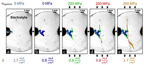
Standard image High-resolution imageIn an unconventional approach, researchers from MIT propose a method to quantify the impact of stack pressure and in-plane stresses on dendrite trajectory using fracture mechanics and also propose design approaches to achieve such stress [200]. The researchers found that the dendrite propagation direction could be deflected with applied stress in the direction perpendicular to the ion transport direction. Operando optical measurements were recorded (figure 11) to capture the propagation visually.
Figure 11. Metal dendrites initiated at 1.7 mA cm−2 galvanostatic current density using the cell geometry demonstrate the progressive growth, deflection, and arrest of dendrites as the load and current density across the cell are varied. Growth segments from each subfigure are highlighted in a separate colour. All images were recorded using strong backlighting (i.e. light positioned below the transparent cantilever). Reprinted from [200], Copyright (2022), with permission from Elsevier.
Download figure:
Standard image High-resolution image
7.3. Terahertz spectroscopy
Terahertz time-domain spectroscopy has been used in many research arenas [201–204]. It was used for the first time to understand the state of SEI in a battery electrode while cycling the cell. The group monitored the cell's impedance at different cycling states to verify that the THz transients are due to the SEI formation (figures 10(g) and (h)). The presented technique shows that terahertz spectroscopy can be a promising tool for operando electrochemical characterisation [199]. THz-TDS can detect alterations of the elusive SEI layer under cycling conditions, and more importantly, during rest periods. Through this study, it is possible to identify the SEI formation on the surface of the Si electrode during the lithiation process, and its partial dissolution during prolonged delithiation.
7.4. Operando x-ray studies
Operando x-ray studies of anodes are a powerful tool for investigating the electrochemical behaviour of anodes during battery operation [205]. These studies use x-ray techniques, such as x-ray absorption spectroscopy or x-ray diffraction (XRD), to probe the chemical and structural changes in the anode material in real-time during battery operation. Operando x-ray studies have provided valuable insights into the behaviour of metal anodes, including lithium metal, sodium, and potassium, in batteries and have helped to improve our understanding of the electrochemical behaviour of these materials. These studies have the potential to aid in the development of safer and more stable metal anode batteries for various applications, including electric vehicles and energy storage systems.
The benefits of operando x-ray studies of anodes include the ability to:
- (1)Observe the evolution of the electrode structure and chemical composition during battery cycling.
- (2)Study the distribution and kinetics of lithium or other metal ions within the anode during battery operation.
- (3)Investigate the reaction mechanisms and kinetics of the electrode/electrolyte interface.
It is difficult to monitor the formation and growth of dendrites and other structures of sodium in real time due to their reactivity and gas evolution.
7.5. TEM studies
Techniques such as TEM cannot be used because the electron beam can possibly damage the material under observation. Even a small exposure time of one second may damage the lithium dendrite [206]. With the micro-electromechanical systems technology in in-situ liquid cell TEM, it has become feasible to observe the deposition and dissolution of dendrites in the charge-discharge cycles. There are a few successful cases of observing metallic dendrites in in situ electrochemical liquid cell experiments, such as lithium dendrite and silver dendrite [207].
By virtue of numerical modelling (e.g. finite element analysis, Monte Carlo calculation, nonlinear phase-field model, data-driven model, and molecular dynamics simulation), great research progress has been made in understanding protective SEI films [208–212]. These computational studies have played a pivotal role in understanding electrochemical battery kinetics owing to the complexity of obtaining real-time interfacial visualisation and quantitative characterisation through experiments. A very strong understanding of dendrite growth is emerged in recent times [213–219] and is beyond the scope of this review.
8. Conclusion and perspectives
The future of lithium metal anodes is promising due to their high theoretical capacity and low electronic conductivity, which offers a potential for higher energy density in batteries. However, there are still some challenges to overcome, such as dendrite growth and instability, which limit their practical application in batteries. Research is ongoing to improve the safety and stability of lithium metal anodes, and if successful, they could play a significant role in the development of high-performance batteries for various applications, including electric vehicles and large-scale energy storage systems. Dendrites are tree-like structures that can form on the surface of lithium metal anodes during repeated charging and discharging cycles. The main drawback of dendrites is that they can penetrate the separator and cause short circuits in the battery, leading to safety issues such as thermal runaway, fire, and explosion. Dendrites can also decrease the overall performance and reliability of the battery by reducing the effective surface area for lithium plating and stripping, and increasing the resistance of the metal anode. Therefore, controlling dendrite growth and improving the stability of lithium metal anodes is critical for the commercialisation of high-performance batteries.
The several approaches being pursued to overcome the problem of dendrite formation in metal anodes as discussed in this article are summarized below.
- (1)Modifying the electrolyte: One approach is to modify the electrolyte to reduce dendrite growth. This can be achieved by adding additives or changing the composition of the electrolyte to suppress dendrite formation.
- (2)Surface modification: Another approach is to modify the surface of the lithium metal anode to reduce dendrite formation. This can be done by coating the surface with a protective layer or by using nanostructured materials.
- (3)Dynamic lithium deposition: Another approach is to use dynamic lithium deposition techniques, such as pulse plating or oscillatory electrolysis, which can prevent dendrite formation by controlling the growth of lithium depositions. There is also a surge in finding alternative methods to produce lithium films to fabricate lithium metal anodes such as vapour, liquid, and electrodeposition techniques.
- (4)Composite anodes: Another approach is to use composite anodes, which consist of a mixture of lithium metal and other materials, such as silicon or graphene, to reduce dendrite formation and improve the stability of the anode.
- (5)Alkali metal alloys: Another approach is to use lithium alloys, such as lithium–aluminium or lithium–copper, instead of pure lithium metal as the anode material. These alloys have been shown to have improved stability and reduced dendrite formation compared to pure lithium.
Strategies to overcome dendrite formation in sodium and potassium batteries are similar to those pursued in lithium metal anodes. Research is ongoing to develop safe and stable sodium and potassium batteries, and the understanding of dendrite formation in these systems is still in its early stages. However, sodium and potassium are abundant and low-cost elements, which make them attractive alternatives to lithium for large-scale energy storage and vehicular applications. There is huge scope for a stable alkali metal anode configuration for all-solid-state batteries and there is also scope for using them as limited metal batteries particularly for solid-state configuration. In order to employ high-capacity cathodes in metal–air and metal sulphur systems, stabilizing metal anodes is the need of the hour. Also, as discussed in the review, including the micro-and/or nano-structuring of alkali metals, introduction of stable hosts, structural modification of current collectors, construction of artificial anode–electrolyte interfaces will lead to the development of microbatteries with higher footprint capacities. Successfully replacing lithium and implementing sodium or potassium metal anodes that can withstand appreciable current density and safety will be the next big leap in battery research.
Acknowledgments
The authors acknowledge IISER Thiruvananthapuram for the financial and infrastructural support. MMS greatly acknowledges the financial support from Department of Science & Technology, Govt. of India (DST/TMD/IC-MAP/2K20/01).
Data availability statement
No new data were created or analysed in this study.
Conflict of interest
There are no conflicts to declare.