

Abstract
We report on the design and characterization of a demonstrator device for miniature-scale elastocaloric (eC) cooling using a series of natural rubber (NR) foil specimens of 9 × 26.5 mm2 lateral size and thicknesses in the range of 290–900 μm. NR has the potential to meet the various challenges associated with eC cooling, as it exhibits a large adiabatic temperature change in the order of 20 K and high fatigue resistance under dynamic load, while loading forces are low. Owing to the large surface-to-volume ratio of rubber-based foils, heat transfer to heat sink and source elements is accomplished by mechanical contact enabling compact designs. Two actuators are implemented to control the performance in loading direction independent from the performance of mechanical contacting. The study of operation parameters is complemented by lumped-element modeling to understand the cycle frequency-dependent dynamics of heat transfer and resulting cooling capacity. The single-stage device operates in the strain range of 300%–700% and exhibits a temperature span up to 4.1 K, while the specific cooling power reaches 1.1 Wg−1 and the absolute cooling power 123 mW. The performance metrics show a pronounced dependence on foil thickness and heat transfer coefficient indicating a path toward future device optimization.
Export citation and abstract BibTeX RIS

Original content from this work may be used under the terms of the Creative Commons Attribution 4.0 license. Any further distribution of this work must maintain attribution to the author(s) and the title of the work, journal citation and DOI.
1. Introduction
Today, a total number of roughly 3 billion devices associated with cooling applications are in use, which accounts for 17% of the total global electricity consumption [1]. Vapor-compression cooling dominates the market, but this conventional technology uses volatile gaseous refrigerants with a high global warming potential (GWP). The climate objective of reducing the overall greenhouse gas emissions by more than 95% until 2050 compared to 1990 levels will require a complete transformation of cooling technology [2]. A promising alternative is elastocaloric (eC) cooling based on mechanical loading-induced temperature changes, which exhibits no environmental impact associated with leakage of the refrigerant, i.e. zero GWP. Depending on the caloric material, intrinsic temperature changes can well exceed 20 K, while the material's efficiency can be close to the thermodynamic limit [3, 4]. Compared to other solid-state cooling technologies large external mechanical stress, electrical or magnetic fields are avoided. eC is therefore one of the most promising non-vapor-compression technologies for future cooling [5].
In recent years, the key properties required for eC cooling have been addressed including the search for material candidates that exhibit (i) a large adiabatic temperature change ΔT, (ii) minimum fatigue, (iii) high materials efficiency and (iv) high thermal conductivity for efficient heat transfer. Currently, the main focus in the quest for a sustainable and viable eC technology is on superelastic shape memory alloys (SMAs), in particular NiTi-based alloys, which exhibit an extraordinary eC effect due to a first order phase transformation [6–8]. TiNiCu-based films, for instance, exhibit an adiabatic temperature change ΔT of 21 K, enable a high material's coefficient of performance (COP) close to the Carnot limit and, most importantly, meet compatibility criteria of martensitic transformation resulting in ultra-low fatigue performance [9–11]. eC cooling devices may be classified into four main categories, namely the type of used eC material, the loading mechanism, the method of heat transfer and the concept of thermodynamic cycling and caloric amplification [12]. Several eC demonstrators have been reported that make use, e.g. of tensile loading of Ti–Ni wires [13, 14] and TiNi-based films [15–17] or compression of NiTi tubes [18–21], which is a promising route to achieve high cyclic stability. A major challenge of using SMA refrigerants, however, is the large stress in the range of 600–800 MPa required for superelastic cycling. Recent work on multicaloric materials demonstrated that the required stress field could be lowered by applying a combination of stress and magnetic fields [22, 23].
For miniature-scale applications, refrigerants of films and foils are of special interest. A specific advantage of these materials is their large surface-to-volume ratio allowing for rapid heat transfer upon mechanical contact without heat transfer fluid. Thus, the design of cooling devices with compact dimensions becomes accessible, which enables addressing the increasing demands, for instance, on local cooling of electronic devices or temperature control of lab-on-chip systems [24–26]. Based on Ti–Ni–Cu films, single-stage eC devices with temperature span of 14 K and specific cooling power of 19 Wg−1 have been developed [16]. The device temperature span has been further increased up to 27.3 K in a cascaded eC system [12]. The increase of overall cooling power has been addressed by parallel operation of SMA films [27]. Yet, material availability and costs are an important issue in this case.
A promising alternative are elastomer materials. Natural rubber (NR) can exhibit distinct temperature changes upon mechanical load cycling [28–31], which is very attractive for eC cooling. Compared to superelastic SMAs, NR materials are much softer and, thus, require much less force for load cycling. NR is environmentally friendly and inexpensive [30], which may facilitate commercialization and may also relax the requirement of long lifetime, as the refrigerant could be exchanged more frequently. The temperature change is caused mainly by two effects, a conformational entropy change due to the alignment of molecular chains and strain-induced crystallization (SIC) [32, 33]. Upon strong stretching, the polymer subchains of the network become ordered during the deformation and SIC of the rubber occurs. Upon strain release, the crystals melt again. Quite high strains of several 100% are needed to yield a strong enough temperature effect [34, 35]. Recently, physics-based models describe crystal formation and melting in stretched NR in dependence of temperature and cross-link density [36, 37]. Many studies on SIC are available and are summarized also in fairly recent reviews [38–40]. A comprehensive review on fatigue in rubber materials was published in [41]. The important parameters for cycling loads are minimum and maximum load and load/unload speeds as well as possible rest periods. The determining internal parameter is SIC [42, 43]. Crystals can stop crack growth and improve stability. In such cases, fatigue is minimized with increasing minimum load, as full melting is avoided in the relaxed state and the remaining crystals hinder crack growth well enough.
However, the implementation of NR materials in an eC cooling device is challenging due to the large strain of up to 700% required for loading and the large strain rate needed to reach adiabatic conditions. Furthermore, NR has a much lower thermal conductivity in the order of 0.15 W m−1 K−1. So far, only a few studies on the development of rubber-based eC cooling devices have been reported [44–46]. A first eC cooling device based on NR tubes has been presented in [44] using water for heat transfer. However, only a temperature span of 1.2 K was achieved at a frequency of 0.3 Hz. In a subsequent work, authors reported a maximum temperature change of 9 K using the concept of regeneration. The cooling power was 1.5 W corresponding to a specific cooling power of 0.14 Wg−1 [46]. An eC device based on an NR membrane was presented in [45], which consisted of a single-stage architecture with pressure supply to inflate an NR membrane using a snap-through instability for rapid expansion and contraction. Heat transfer was realized by mechanical contact between the membrane and spherically shaped high and low temperature reservoirs. A maximum temperature change of 7.9 K was obtained for an NR membrane of 140 μm thickness at an operation frequency of 1.1 Hz. The cooling power and maximum specific cooling power were 0.87 W and 20.9 Wg−1, which was achieved at the expense of low efficiency (COP ∼ 1). The reported low number of operation cycles in the order 103 was ascribed to operation partly in the amorphous regime.
Here, we present a different device concept targeting at miniature-scale eC cooling based on NR foil refrigerants. Heat transfer is accomplished by mechanical contact between the NR foils and planar heat sink/source elements. The device consists of a single-stage architecture comprising two actuators to independently control the parameters of load cycling and mechanical contacting. We investigate the effects of NR foil thickness and various operation parameters on the performance metrics of temperature span, COP and cooling capacity. The experimental investigation is complemented by lumped-element modeling (LEM) simulations on the dynamics of heat transfer to elucidate the optimal operation conditions for eC cooling.
2. Material properties
Two different kinds of NR foils are utilized as the eC refrigerants. NR foils of thicknesses 900 and 650 μm were obtained from a commercial supplier (IHSD-Klarmann), while thin foils of 290 μm have been manufactured in-house by a casting process. The compounds and procedure are described in table T1 of the supplementary information. A series of test specimens was fabricated by laser cutting to investigate the eC material properties under uniaxial tensile loading conditions. Temperature changes were determined as a function of maximum strain, pre-strain and strain rate by infrared thermography. The temperature measurements were made in strained und undeformed state at a constant holding time. All tests were performed after stabilization within the first ten cycles due to the Mullins effect [47].
The eC effect is demonstrated in figure 1 for an NR foil of 650 μm thickness. By rapidly stretching the foil until a maximum strain of 700%, latent heat is released causing a temperature increase by 8.7 K of the NR specimen. After sufficient waiting time to allow for equilibration of temperatures between the NR foil temperature and the environment, rapid unloading causes a temperature decrease well below the environmental temperature by −10.3 K. The difference of temperature changes upon loading and unloading is attributed to the different kinetics of crystallization [48, 49]. The characterization of temperature changes as a function of maximum engineering strain is depicted in figure 2(a) for an NR film of 650 μm thickness. In the strain range up to about 300%, only minor temperature changes occur, which are almost linear reflecting the entropic elasticity due to alignment of molecular chains [33]. At larger strain levels, temperatures exhibit a large nonlinear change due to SIC and eventually saturate above 700%. The overall temperature span of the material ΔTmat given by the difference of maximum hot and minimum cold temperature (ΔTh − ΔTc) reaches more than 20 K at 800%. From this measurement, we can infer that the interesting strain regime for eC cooling, where most of the temperature change occurs, is between about 300% and 700%. Therefore, the design of the eC cooling devices presented in section 3 is tailored for a pre-strain of 300%, while the upper strain limit is chosen to be 700%. This restriction to the SIC regime is beneficial for the cyclic lifetime of the material [30] and, furthermore, it relaxes the requirements on actuation stroke.

Figure 1. (a) Surface temperature of an NR foil of 650 μm thickness after rapid stretching by 700% at a strain rate of 4.7 s−1 (1), after thermal equilibration in stretched state and subsequent rapid unloading at a strain rate of 4.7 s−1 (2); (b) corresponding time-resolved evolution of temperature change ΔT.
Download figure:
Standard image High-resolution image
Figure 2. (a) Maximum hot and minimum cold temperature ΔTh and ΔTc as a function of maximum engineering strain for an NR film of 650 μm thickness at a strain rate of 4.7 s−1; (b) corresponding stress–strain characteristics under uniaxial loading for different maximum strain as indicated.
Download figure:
Standard image High-resolution imageFigure 2(b) shows the corresponding stress–strain curves. At low strain below 100%, the NR foil exhibits almost elastic behavior. At higher strain levels above 200%, a plateau-like increase of stress occurs reflecting the course of SIC. The maximum stress is in the order of few MPa. Unloading occurs at significantly lower stress levels as SIC causes stress relaxation [29]. Thus, in all cases, a hysteresis is observed, which increases with increasing maximum strain. The area enclosed by the hysteresis indicates the work input ΔW needed for eC cycling assuming work recovery upon unloading. With increasing strain, the maximum engineering stress increases as well as the stress relaxation upon loading. The strain rate dependence of the stress–strain characteristics is represented in figure S2 in the supplementary information. While the maximum engineering stress and stress relaxation increase for increasing strain rate, almost no strain-rate dependence is observed during unloading. As a net-effect, the increase of strain and strain rate cause an increase of work input.
Loading and unloading needs to be fast enough to minimize unwanted parasitic heat flows and to record the temperature change of the NR foils. The strain rate-dependence of the observed temperature changes is shown in figure 3(a) for an NR foil of 650 μm thickness and a fixed maximum strain of 700%. Quasi-adiabatic conditions for unloading are reached at a strain rate above about 4.7  , at which the deviation of the minimum temperature
  with respect to the value at maximum strain rate of 14
  is below 5%. As the melting process of crystallites starts at a lower strain compared to the crystallization process, a higher strain rate is needed to reach adiabatic conditions upon loading. The strain rate required for quasi-adiabatic conditions for unloading depends on the film thickness. While a strain rate of 0.7
  is sufficient for 900 μm thick specimens, the minimum strain rate increases to 9.3
  for NR foils of 290 μm thickness. Thereby, the hysteresis of the stress–strain curves needs to be taken into account, as it is increasing for increasing strain rate and thus causes an increase of the required work input ΔW. Therefore, a compromise has to be found in terms of achieving a large enough temperature change during unloading ΔTC and a low enough work input ΔW.

Figure 3. (a) Maximum hot and minimum cold temperature ΔTh and ΔTc as a function of strain rate for an NR film of 650 μm thickness at a maximum strain of 700%; (b) absorbed latent heat Qab, work input ΔW and coefficient of performance of the material  versus engineering strain.
Download figure:
Standard image High-resolution image
Based on the results on ΔTC and ΔW, the performance metrics of the NR foils are evaluated for comparison of eC material properties. Figure 3(b) summarizes the major results on the pre-strain dependence of absorbed latent heat Qab, the work input ΔW and the COP of the material  , which is determined by the ratio of Qab and ΔW for one load cycle:

whereby  denotes the absorbed latent heat and m is the mass of the refrigerant. The definition of COPmat should relate to a thermodynamic process cycle, however, the given definition in (1) is not always used in this way. Therefore, it was suggested to refer to it as 'materials efficiency' rather than COPmat [50] or to define the COP based on a reverse Sterling or Brayton cycle [3, 51]. Although the definition in (1) is under debate, it is still widely used in the field of eC cooling. Nevertheless, a direct comparison of different COPmat values from literature is only recommended for similar experimental conditions. Both, the absorbed latent heat and the required work input ΔW decrease for increasing pre-strain. However, since ΔW decreases faster, the
  shows a maximum of about 6 at the pre-strain of 300%. In this case, the temperature change during unloading ΔTC reduces to about −7.8 K.
The main results on the eC properties of the investigated NR foils are summarized in table 1. The strain rate required to reach quasi-adiabatic conditions strongly depends on the NR foil thickness. The minimal strain rate increases from 0.7 s−1 at 900 μm foil thickness d to 9.3 s−1 for d = 290 μm. A pre-strain of about 300% is useful to make use solely of the SIC effect, which is beneficial in terms of cyclic lifetime and reduced actuation stroke. The 290 μm thick foils show lower values of temperature change and COP compared to 650 and 900 μm thick NR foils, which reflects the variation in eC properties depending on material fabrication.
Table 1. Summary of elastocaloric material properties of the investigated NR foils having different thicknesses d. Legend:  —pre-strain,
  —maximum strain,
  —strain rate, Δw—specific work input, ΔTc—minimum cold temperature, ΔTmat—temperature span of the material, Qab—absorbed latent heat,
  —coefficient of performance of the material.

![$\left[ {\mu {\text{m}}} \right]$](https://content.cld.iop.org/journals/2515-7655/6/1/015009/revision2/jpenergyad0cffieqn15.gif)
|
![${\varepsilon _{{\text{pre}}}}{\text{ }}\left[ \% \right]$](https://content.cld.iop.org/journals/2515-7655/6/1/015009/revision2/jpenergyad0cffieqn16.gif)
|

![$\left[ {{\% }} \right]$](https://content.cld.iop.org/journals/2515-7655/6/1/015009/revision2/jpenergyad0cffieqn18.gif)
|

![$\left[ {{{\text{s}}^{ - 1}}} \right]$](https://content.cld.iop.org/journals/2515-7655/6/1/015009/revision2/jpenergyad0cffieqn20.gif)
| ΔW
![$\left[ {{\text{J}}{{\text{g}}^{ - 1}}} \right]$](https://content.cld.iop.org/journals/2515-7655/6/1/015009/revision2/jpenergyad0cffieqn21.gif)
|

![$\left[ {\text{K}} \right]$](https://content.cld.iop.org/journals/2515-7655/6/1/015009/revision2/jpenergyad0cffieqn23.gif)
|

![$\left[ {\text{K}} \right]$](https://content.cld.iop.org/journals/2515-7655/6/1/015009/revision2/jpenergyad0cffieqn25.gif)
|

![$\left[ {{{\text{Jg}}^{ - 1}}} \right]$](https://content.cld.iop.org/journals/2515-7655/6/1/015009/revision2/jpenergyad0cffieqn27.gif)
|

|
|---|---|---|---|---|---|---|---|---|
| 900 | 0 | 700 | 0.7 | 5.2 | −10.0 | 17.4 | 18.8 | 3.6 |
| 900 | 300 | 700 | 0.7 | 1.7 | −6.4 | 12.3 | 12.0 | 6.9 |
| 650 | 0 | 700 | 4.7 | 7.1 | −10.3 | 19.0 | 19.5 | 2.7 |
| 650 | 300 | 700 | 4.7 | 2.4 | −7.8 | 12.4 | 14.6 | 6.0 |
| 650 | 300 | 700 | 9.3 | 3.6 | −7.9 | 13.1 | 14.9 | 4.1 |
| 290 | 0 | 700 | 4.7 | 6.5 | −8.4 | 13.1 | 15.7 | 2.4 |
| 290 | 300 | 700 | 4.7 | 3.0 | −5.5 | 8.0 | 10.3 | 3.4 |
| 290 | 300 | 700 | 9.3 | 2.9 | −6.4 | 10.6 | 12.0 | 4.1 |
3. Cooling concept and device layout
Figure 4 illustrates the operation principle of the eC device, which corresponds to an inverse Brayton cycle. In initial state, the NR foil is at room temperature. By applying a tensile load in x-direction, the NR foil is stretched under quasi-adiabatic conditions causing the release of latent heat due to entropy elasticity and SIC, which leads to a temperature increase of the refrigerant (I). The heat is rejected to the heat sink by actuation in y-direction to enable solid–solid mechanical contact, whereby the temperature of the heat sink increases and the refrigerant temperature decreases again to room temperature (II). Rapid unloading results in a reverse transformation and adiabatic cooling of the refrigerant (III). While in mechanical contact to the heat source, latent heat is absorbed causing a temperature decrease of the heat source and a temperature increase of the refrigerant back to room temperature.

Figure 4. Schematic of the eC cooling cycle. The cooling cycle can be divided into four steps: mechanical loading and heating (I), heat rejection to a heat sink (II), unloading and cooling (III) and heat absorption from a heat source (IV). The forces for tensile un/loading and for providing mechanical contact to the sink/source are denoted by Fx and Fy , respectively.
Download figure:
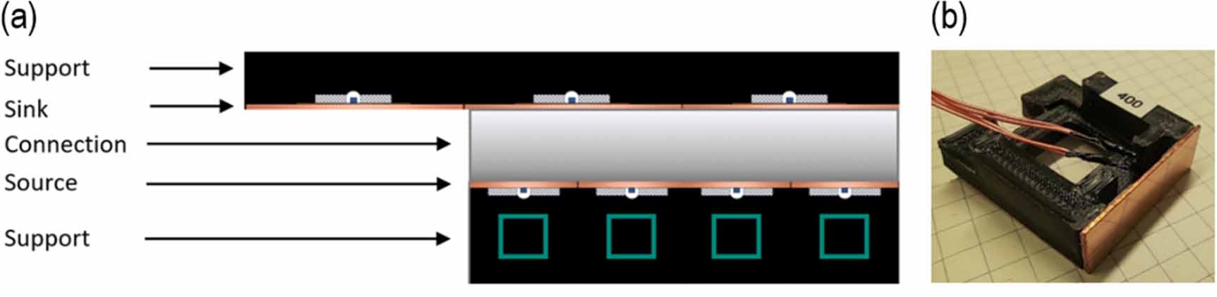
Standard image High-resolution imageThe NR foil refrigerants are implemented in a device for miniature-scale eC cooling. In the following, a single-stage architecture is presented to investigate the various operation parameters. An actuation mechanism is developed to meet the intended strain levels of up to 700% and strain rates up to 9.7 s−1. As the stress level is in the order of a few MPa, this performance can be achieved by tensile loading using a conventional electromotor. Furthermore, in the present investigation, directional heat transfer is accomplished by alternating mechanical contact of the foil refrigerant and planar heat sink and source elements. For this purpose, an additional actuator with small actuation stroke is used, which can be adjusted independently of tensile loading to optimize contact force and contact time. Figure 5(a) shows a schematic of the demonstrator device. Sink and source elements consist of non-conducting support structures of a polymer fabricated by 3D printing and copper plates of 1 mm thickness forming the sink and source elements. A serial arrangement of several sink and source elements above and below the foil refrigerant is designed in a modular way to implement discrete strain levels in steps of 100% by adding or removing modules. A single module is shown in figure 5(b). PT100 temperature sensors are incorporated at the backside of the copper plates in each module to monitor the evolution of temperature.

Figure 5. (a) Schematic of the miniature-scale eC device; variable pre-strains are realized by modular source elements; (b) photo of a modular source element.
Download figure:
Standard image High-resolution image4. LEM simulation of eC cooling performance
Heat flows at the different thermal interfaces are simulated using Matlab Simscape. A schematic of the LEM is shown in figure 6. Major components of the eC device are the NR foil, copper sink and source elements and supporting polymer structures. The eC effect in the NR foil is modeled by a heat pulse that takes place at the end of the loading and unloading process with alternating sign. The resulting temperature change is assumed to be evenly distributed within the NR foil according to the measured values presented in section 2. The eC device is discretized in elements, which are chosen to be thermally thin having a single uniform temperature. The elements are coupled to each other via heat resistances R = h−1A−1
, whereby h denotes the heat transfer coefficients and A is the contact area. Different heat resistances are considered reflecting the heat transfer by heat convection to the surrounding air and heat conduction in between the NR elements. In particular, the convective heat transfer at the free surfaces of the NR foil is described by a heat transfer coefficient  = 25 W m−2 K−1. Of special interest is the heat transfer coefficient
  at mechanical contact between the NR foil and the sink/source elements, which is modeled by event triggered switches. By comparing the simulated and experimental temperature changes, we determined
  to be about 120 and 80 W m−2 K−1 for an NR foil thickness of 650 and 290, respectively. The model considers the strain-dependent changes of thickness and width of the NR foil to accurately describe the resulting changes of contact area and heat transfer time. Based on the resulting time-dependent temperature changes in the sink and source elements, the cooling power and COP are determined as a function of operation frequency and NR foil thickness. The material parameters used for LEM simulations are summarized in tables T2 and T3 in the supplementary information.

Figure 6. Schematic of the lumped element model (LEM). The eC device is discretized in elements (thermal capacitors) that are coupled to each other via heat resistances describing the heat transfer by heat convection to the surrounding air  and heat conduction
  . The heat transfer between the NR foil and sink/source is described by
  . Lines connecting each thermal resistance and thermal capacitance represent bidirectional heat flow paths. Legend: PLA—polylactide , eC—elastocaloric.
Download figure:
Standard image High-resolution image5. Device characterization
Figure 7(a) shows the temperature changes of heat sink and source versus time for a demonstrator device with an NR foil of 650 μm thickness. Loading and unloading is performed in the strain range between 300% and 700% at a strain rate of 9.3 s−1. Initially, each load cycle leads to an overall increase of the temperature difference between sink and source of the device ΔTdevice. ΔTdevice increases during the time periods of heat transfer to the sink in step II and to the source in step IV (figure 4). During the other time periods, ΔTdevice decreases slightly due to parasitic heat flow. After the initial temperature change, saturation occurs after about 50 s at the hot side and about 100 s at the cold side. The temperature difference reaches a maximum of about 4.1 K. The operation frequency is 136 mHz, which corresponds to the optimal frequency in this case as shown in figure 7(b). The inset of figure 7(b) illustrates that the frequency is given by the loading and unloading times and the holding time of 3 s. Throughout the holding time, the NR foil stays in its deformed state either at 300% or 700% and exchanges heat with the sink or source, respectively. At the strain rate of 9.3 s−1, the loading and unloading times are both 430 ms. Due to experimental reasons, an additional tolerance of 250 ms has been considered. At the optimal frequency, ΔTdevice reaches its maximum indicating an optimal balance between heat transfer and heat losses. At lower frequencies, losses become more dominant and the temperature change decreases. At higher frequencies, the holding time becomes too short to enable sufficient heat transfer.

Figure 7. (a) Temperature evolution of heat sink (red) and source (blue) with respect to room temperature at a frequency of 136 mHz for a demonstrator device with an NR foil of 650 μm thickness. At the strain rate of 9.3 s−1, the loading and unloading times are 430 ms. (b) Maximum temperature span of the device ΔTdevice versus frequency. The error bars are determined by the measurement accuracy of the temperature sensors. Inset: the frequency is given by the time durations of loading and unloading  , and the holding times
  to enable heat transfer to sink and source. Legend:
  —pre-strain,
  —maximum strain.
Download figure:
Standard image High-resolution imageHowever, this performance depends on the film thickness. For the demonstrator device based on an NR foil of 290 μm thickness, we find an optimal frequency of about 230 mHz. In this case, the optimal holding time reduces to 1.5 s. In addition, ΔTdevice is smaller indicating that less heat is absorbed and generated at the given strain rate due to the lower mass of the refrigerant. The use of NR foils of 900 μm thickness leads to poor demonstrator performance. Due to the low thermal conductivity of the refrigerant, heat transfer is too slow in this case and a large fraction of heat remains in the NR foil without reaching the sink and source. Thereby, cycling times become too long and parasitic heat flow dominates the performance. This indicates that the NR foil thickness imposes a clear limitation to miniature-scale eC cooling when using the concept of heat transfer by direct mechanical contact. In the following, we therefore restrict our detailed investigation on demonstrator devices with NR foils of 650 and 290 μm thickness.
Figure 8(a) shows corresponding simulated and experimental results on the cooling power versus frequency. The cooling power shows a pronounced maximum at an optimal frequency, which shifts to higher frequencies for decreasing NR foil thickness. This performance correlates with the frequency-dependent change of ΔTdevice shown in figure 7(b). For the NR foil of 650 μm thickness, the maximum cooling power determined from the experimental data is 123 mW at 136 mHz, which corresponds to a specific cooling power of 954 mWg−1. The corresponding LEM simulation of the cooling power reproduces the frequency-dependent maximum. However, it shows a more gradual decrease at higher frequencies, which is attributed to assuming a frequency-independent convective heat transfer to the environment in the LEM simulations. For the NR foil of 290 μm thickness, the maximum cooling power reaches about 78 mW at 230 mHz. The corresponding absolute cooling power is 1082 mWg−1 reflecting the smaller mass of the refrigerant. The higher optimal frequency indicates that heat transfer occurs more rapidly allowing for more cooling cycles in a given time period.

Figure 8. (a) Cooling power versus frequency determined by LEM simulations and experiments on demonstrator devices with NR foil thicknesses of 650 and 290 μm. The error bars are determined by the average of a measured series; (b) corresponding device COP versus frequency.
Download figure:
Standard image High-resolution imageThe efficiency of the eC demonstrator devices COPdevice is determined by the ratio of cooling capacity at zero thermal load and the input power needed for operation:

whereby f is the frequency of operation. The mechanical work input per cycle of operation ΔWdevice is calculated by integrating the applied force

Thereby, we assume work recovery, i.e. we consider the hysteresis work during loading and unloading, while the actuator efficiency is not taken into account. The frequency dependence of experimental and simulated COP values of the devices is depicted in figure 8(b). Similarly, a maximum COP is found at an optimal frequency, which shifts to higher frequencies for decreasing NR foil thickness. At too low frequency, the efficiency decreases as not enough heat/cold is generated. Once the frequency increases beyond its maximum value, the contact time for heat transfer becomes too short, while the input work further increases. The maximum COP is about 4.7 at 136 mHz for the NR foil of 650 μm thickness and about 4.0 at 230 mHz for the 290 μm thick NR foil. A summary of experimental results on the eC demonstrator device is provided in table T4 in the supplementary information.
6. Discussion
We present an investigation of the eC cooling properties of miniature-scale eC cooling devices based on a single-stage architecture using NR foil refrigerants of different thicknesses ranging from 900 μm to 290 μm in undeformed state. It is important to note that the NR foil thickness reduces considerably upon loading due to the large strain during device operation. For instance, the 290 μm thick foil decreases down to a thickness of about 80 μm at 700%. This strain-dependent change of refrigerant dimensions needs to be taken into account in the device design and optimization of heat transfer. Tables T2 and T3 in the supplemental information give an overview on the change of refrigerant dimensions as a function of strain.
The interesting strain regime for eC cooling is between about 300% and 700%, where most of the temperature change occurs due to SIC. The overall temperature change of the NR foils ΔTmat reaches almost 20 K at 700%. Another important property of NR-based eC devices is the required low work input ΔW in the range of a few MPa, which is given by the hysteresis of the stress–strain characteristics of the NR refrigerants. A large strain rate is beneficial for high ΔTmat. However, the work input ΔW is increasing for increasing strain rate and, therefore, a compromise has to be found regarding a sufficiently high ΔTmat and a low enough ΔW. The  shows a maximum of about 6 at the pre-strain of 300%, as the work input ΔW at low pre-strain decreases more strongly compared to the absorption of latent heat for increasing pre-strain. The favorable properties of ΔTmat, ΔW and
  as well as the low material costs are a major motivation to investigate and exploit the use of NR foils for eC cooling.
The key concept for heat transfer in the eC device relies on mechanical contact between the foil refrigerant and heat sink/source elements. Therefore, a second actuator is used to control contact forces and holding times for maintaining the required solid–solid mechanical contact. The mechanical contact has to be optimized for each NR foil thickness to achieve a large maximum ΔTdevice and maximal cooling power. If the holding time is too short, heat transfer remains insufficient. At too long holding times, parasitic heat flows become increasingly dominant and ΔTdevice decreases. Indeed, parasitic heat flows at the sink during the loading times and the holding time at the source and vice versa lead to small oscillations of sink and source temperatures during eC cycling. These oscillations are minimized by keeping the holding times short enough and the loading/unloading rates sufficiently fast. For device operation, we use a loading/unloading rate of 9.3 s−1, at which the foil refrigerants approach their maximum ΔTdevice values. Larger loading/unloading rates are avoided as they pose high demands on actuation performance and cause an unwanted increase of work input per cycle.
The investigated single-stage eC devices reveal maximum ΔTdevice values up to 4.1 K and a COPdevice of 4.7, which are significantly lower compared to the corresponding eC properties of the NR foil materials. Maximum values of specific cooling power increase for decreasing thickness of the foil refrigerant and reach about 1.1 Wg−1 for the lowest thickness. A pronounced dependency of the performance metrics on the eC cycling frequency is observed. These results indicate the importance of heat transfer and that control of heat transfer dynamics plays a key role in further optimization of eC.
High reversibility is an important requirement to enable operation at sufficiently long lifetime. We performed a preliminary study on the cyclic performance up to 104 cycles that revealed no temperature change within the experimental error, see figure S6 in the supplementary information. This result is in line with reported fatigue measurements on NR specimens under the condition of SIC forming a crystallization network, which can effectively prevent crack formation and growth [42, 43]. Previous high-cycle tests up to 1.7 × 10⁵ in [52] and 107 in [53] confirm this performance.
The thickness-dependent dynamics of heat transfer has been further investigated by LEM simulations. Figure 9(a) shows the simulated thickness-dependence of optimum frequency to reach maximum cooling power during eC cycling assuming thickness-independent heat transfer coefficients h. A considerable increase of optimum frequency is obtained for decreasing NR foil thickness and for increasing heat transfer coefficient. The thickness dependence of optimum frequency is due to the large strain-dependent decrease of foil thicknesses and contact areas. In particular, heat transfer at mechanical contact between NR foil and source occurs at the pre-strain of 300%, at which the foil thicknesses reduce from 650 to 270 μm and from 290 to 150 μm. The corresponding times to transfer 70% of heat at mechanical contact are about 3.0 and 1.5 s, respectively, which is in line with the experimentally found thickness-dependent optimum holding times  and optimum cycling frequencies.

Figure 9. (a) LEM simulations of optimum frequency to reach maximum cooling power during eC cycling versus NR foil thickness for different heat transfer coefficients h as indicated; (b) corresponding simulations of specific cooling power.
Download figure:
Standard image High-resolution image
The corresponding simulated thickness-dependence of specific cooling power is shown in figure 9(b). The specific cooling power strongly increases for decreasing foil thickness. In particular, by reducing the foil thickness from 290 to 100 μm, we expect an increase of specific cooling up to about 3.8 Wg−1 assuming a constant heat transfer coefficient h of 120 Wm−2 K−1. In addition, the eC cooling performance strongly benefits from increasing the heat transfer coefficient h. For the eC device with a foil thickness of 290 μm, a moderate increase of h from 120 to 240 Wm−2 K−1 already leads to a specific cooling power of about 3 Wg−1. Thus, both thickness reduction and increase of heat transfer are effective means to enhance eC performance. The simulation trends indicate that there is a large potential for performance improvements, both in terms of eC material properties and device design. Dedicated eC elastomers need to be developed specifically for eC applications with tailored properties like enhanced eC effect, increased thermal conductivity as well as optimal foil thickness and smooth surface finish. Heat transfer could be further optimized, e.g. by increasing heat conductivity and introducing additional surface layers. Additional measures for thermal insulation of sink and source would further minimize parasitic heat flows.
7. Conclusions
We present a novel miniature-scale lightweight eC cooling device based on NR foil refrigerants, which relies on heat transfer via mechanical contact between foil refrigerant and heat sink/source elements. Heat-transfer fluid-free operation eliminates the risk of leakage and allows for an environmentally friendly solution. This work is motivated by the large eC temperature changes of NR foil refrigerants upon loading/unloading reaching +8.7/−10.3 K at 700% strain, while the material's COP can exceed 6. The presented eC device consist of a single-stage architecture comprising two actuators to independently control the parameters of load cycling and mechanical contacting. We investigate the effects of NR foil thickness and various operation parameters on the performance metrics of temperature span, device COP and cooling capacity. The eC devices reveal maximum ΔTdevice values up to 4.1 K and a COPdevice of 4.7. The specific cooling power increases for decreasing thickness of the foil refrigerant and reaches about 1.1 Wg−1 at 290 μm foil thickness. LEM simulations on the dynamics of heat transfer reveal optimum eC cycling frequencies to reach a maximum cooling power of 136 and 230 mHz for NR foil thicknesses of 650 and 290 μm, respectively, which confirm our experimental results. In addition, the LEM simulations indicate that the eC cooling performance can be improved significantly by the development of dedicated eC elastomers with tailored thickness below 290 μm and enhanced heat transfer properties. Further reduction of NR foil thickness leads to a decrease of absolute cooling power, which could be compensated by developing parallel eC architectures consisting of NR foil arrays. Next generation devices may also consider cascaded eC architectures to increase the overall temperature span.
Acknowledgments
This work was funded by the German Science Foundation (DFG) through the Projects KO2953/16-1 and RU 489/39-1.
Data availability statement
The data cannot be made publicly available upon publication because they are not available in a format that is sufficiently accessible or reusable by other researchers. The data that support the findings of this study are available upon reasonable request from the authors.
Supplementary data (0.6 MB PDF)