

Abstract
The 15 short chapters that form this 2023 ammonia-for-energy roadmap provide a comprehensive assessment of the current worldwide ammonia landscape and the future opportunities and associated challenges facing the use of ammonia, not only in the part that it can play in terms of the future displacement of fossil-fuel reserves towards massive, long-term, carbon-free energy storage and heat and power provision, but also in its broader holistic impacts that touch all three components of the future global food-water-energy nexus.
Export citation and abstract BibTeX RIS

Original content from this work may be used under the terms of the Creative Commons Attribution 4.0 license. Any further distribution of this work must maintain attribution to the author(s) and the title of the work, journal citation and DOI.
1. The ammonia energy roadmap: renewable chemically energised water for a clean-air, fossil-free future
William I F David1,2
1ISIS Neutron and Muon Source, STFC Rutherford Appleton Laboratory, Harwell Science and Innovation Campus, Didcot OX11 0QX, United Kingdom
2Inorganic Chemistry Laboratory, University of Oxford, South Parks Road, Oxford OX1 3QR, United Kingdom
Email: bill.david@stfc.ac.uk
Overview
The 15 short sections that form this 2023 ammonia-for-energy roadmap provide a comprehensive assessment of the current worldwide ammonia energy landscape and the opportunities and associated challenges facing the use of ammonia, not only in the part that it can play in terms of the future displacement of fossil-fuel reserves towards massive, long-term, carbon-free energy storage and heat and power provision, but also in its broader holistic impacts that touch all three components of the future global food-water-energy nexus.
An energy roadmap that focusses on ammonia as chemically energised water produced from renewable sources represents a future direction that is distinctive in emphasis from both the all-electric scenario of batteries and the promise of a future hydrogen energy economy powered by hydrogen fuel cells.
For the past one hundred years, ammonia has been used as the principal feedstock for inorganic fertilisers and has been of fundamental importance in providing sufficient food to feed our planet [1, 2]. As the 21st century progresses, net-zero ammonia has the additional potential to make an equivalently significant impact through enabling the transition away from our global dependence on fossil fuels and contributing, in substantial part, to the reduction of greenhouse gas emissions. As an overlooked advantage that parallels the emergence of battery electric cars (BEVs) as zero-emission vehicles, today's ammonia is already in a positon to help eliminate harmful emissions and address health issues associated with poor air quality (see section 2).
It is important in outlining this future ammonia energy roadmap to recognise its role not only in the distributed delivery of fossil-free power but also in the worldwide provision of carbon-free energy reserves. With our awareness of the impact of CO2 emissions on global warming, what often comes first to mind are fuels such as petrol and diesel that power internal combustion engines (ICEs) and produce emissions. These fuels must be abandoned. Unfortunately, though it should not be so, the demise of the ICE is often conflated with this move away from fossil fuels. Noting that there are around two-billion ICEs on the planet (1.4-billion of which power light vehicles [3]), it would be imprudent to ignore this technology as we head for net-zero in 2050 and the opportunities it may bring for a just transition. Future low emissions for ICEs are discussed extensively in this article (sections 11–13).
The demise of the ICE is, however, the anticipated future paradigm, particularly in Europe [4]. Battery electric vehicles (BEVs) are seen to be the way forward for passenger cars but with only 26 million BEVs on the road today across the world and a potential 100 million by 2030, replacing 1.4 billion ICEs is well out of reach. Moreover, despite a decade of BEVs, no significant market penetration has been achieved into other ICE markets such as trucks, trains and ships [5].
The only other motive power technology under consideration at present is hydrogen fuel-cell transportation. This, however, is a technology, despite over a decade of development, which does not have a global impact; there are currently only ∼800 operating hydrogen refuelling stations worldwide [6] and the global number of hydrogen fuel-cell vehicles at the end of 2022 was ∼72 000 [7].
Despite, the long history of ammonia-fuelled ICEs [8], it is only recently that the notion of retrofitting internal combustion engines based around ammonia has begun to gain traction. 2020 global ammonia production was 182.6 Mt with the capacity to reach 224.6 Mt [9]. The 42 Mt spare capacity could power ∼35 million cars which is similar in magnitude to BEVs and 500× higher than hydrogen fuel-cell vehicles. The smart money should be on future battery-ammonia hybrids. Based upon the global ammonia infrastructure, direct-ammonia solid-oxide fuel cells offer an attractive alternative (see section 9).
ICEs are criticised because of their emissions. With ammonia combustion, there are zero CO2 emissions and no carbonaceous particulates. NOx emissions and ammonia slippage are seen as the Achilles heel of ammonia-fueled ICEs. Recent research (see section 10), however, has shown that a ∼70:30 blend of ammonia and cracked-ammonia performs with ppm levels of NOx emissions on a par with petrol and diesel engines. The technical challenge is to reduce these emissions to safe environmental ∼ppb levels; the technologies exist to achieve this level of excellent and safe air quality.
Figure 1 illustrates the striking difference between the distribution of fuel types for primary energy consumption and primary energy storage. While coal, oil and gas account for 82% of primary energy provision [10], the no-carbon energy options together amount to a significant 18% fraction which is set to grow substantially, particularly in the areas of wind and solar. This is not the case for primary energy storage and distribution which is currently dominated, at 97%, by fossil fuels. The remaining 3% (∼4.3 × 10³ TWh yr−1) is currently provided by pumped hydroelectric energy storage (PHES) [11] which, with a timescale of hours and days, does not address longer term, interseasonal energy storage. Two other potential storage technologies, Li-ion batteries and ammonia, which both have existing infrastructures are included in figure 1. With year-on-year cumulative global Li-ion battery capacity of ∼1.5 TWh at the end of 2022 [12], a 24 h charge-discharge regime corresponds to ∼0.5 PWh year−1. This 2022 capacity is set to increase by an order of magnitude by 2030 when it will be equivalent in size to global PHES storage capacity. Notably, however, both PHES and battery energy storage are short-term, essentially intra-day solutions.

Figure 1. (left) The 2022 distribution of global primary energy consumption obtained from the 2023 Statistical Review [10]; (right) The 2022 distribution of primary energy storage: coal, oil and gas are energy storage technologies prior to their consumption. PHES is the only fossil-free technology that is currently operational. The battery and ammonia-based storage values were calculated based on the scale of the existing battery and ammonia infrastrucures and represent their respective potential global storage opportunities. The energy numbers in the pie charts are in units of PWh (1PWh = 103 TWh).
Download figure:
Standard image High-resolution imagePHES and battery intra-day energy storage solutions make a crucial but only partial contribution to a future energy infrastructure. The scale and function of a 2050 global carbon-free energy infrastructure must be commensurate and align with the principal aspects of existing fossil-fuel energy storage. This is particularly important in terms of fuel transportation and the provision of long-term storage that ranges from days and weeks up to interseasonal and multi-year durations.
While there are substantial challenges in the transportation of hydrogen as a fuel, it is considered to be a potential candidate for long-term renewable energy storage for electricity provision, using salt mines where available as an option [13]. The challenge, however, is that although the 2022 annual global production of hydrogen is ∼80 Mt, almost all the hydrogen is immediately used onsite for the refining of oil or the production of ammonia and methanol. The 2022 global hydrogen storage infrastructure is not commensurate with its ∼80 Mt production, consisting of (i) ∼800 hydrogen refuelling stations worldwide [6] (which equates to 12 000 tonnes H2 year−1), and (ii) liquid hydrogen production and storage of ∼127 000 tonnes year−1 [14]. Together, this equates to a 2022 global specifically hydrogen storage infrastructure corresponds to ∼0.005 PWh year−1. This is in strong contrast to the current ammonia infrastructure which has an equivalent energy storage of ∼1.2 PWh year−1.
The 2022 ammonia infrastructure is almost entirely based on natural gas. In 2019, global ammonia production resulted in ∼500 Mt yr−1 CO2 emissions, equivalent to ∼1.5% of global CO2 emissions [8]. As a comparative sense of scale, the UK and Germany respectively emit ∼340 Mt yr−1 and ∼630 Mt yr−1 of CO2. Decarbonisation of ammonia production is one of the major industry transitions that must be achieved in tackling global warming as we head for a carbon-free energy future.
From an infrastructure perspective, ammonia is the most realistic future carbon-free replacement for fossil fuels. However, the scale-up required over the next quarter century is particularly challenging in principal part because of the need to move to carbon-free ammonia production. The development of TW-scale electrolyser global capacity (section 4) represents the main challenge. The redefining of the Haber-Bosch process powered by intermittent renewable energy (section 5) must also be addressed. Electrochemical and photochemical ammonia production are currently distant opportunities to explore (section 6) and the opportunities offered by nuclear energy should be investigated.
Roadmap summary
- The roadmap begins with a description of the current status of the global ammonia infrastructure and the opportunity to address immediately the challenges of air quality and zero-emissions zones prior to tackling full-scale decarbonisation (section 2).
- Sections 3 and 4 discuss immediate future opportunities
- Existing ammonia production must move away from the two-stage route of steam reformation of methane (SMR) followed by the traditional Haber-Bosch process. Water electrolysis supplants SMR. Scale-up is a major challenge and all electrolysis options must be explored with due consideration of the supply of critical materials and recyclability (section 5).
- Future electrochemical and photochemical methods of ammonia synthesis are long-term research projects that have the potential to be transformative if scale-up can be achieved (section 6).
- Options are presented for modification of the Haber-Bosch process, which will only operate efficiently in the future if the issues associated with the intermittency and irregularity of renewable energy production are addressed (section 7).
- Ammonia storage, transportation and delivery are all well-established features of the existing global infrastructure; section 8 discusses an integrated global perspective.
- Ammonia and hydrogen are both carbon-free fuels for heat and power provision. However, recent research has shown that ammonia-hydrogen blends offer improved performance. Section 9 discusses the catalyst challenges of transforming ammonia to ammonia-hydrogen (and nitrogen) blends.
- Fuel cell emissions are benign for both ammonia and hydrogen fuels and make fuel cells an attractive technology for the provision of clean power at high efficiency. Section 10 discusses the different fuel cell options for ammonia and ammonia-hydrogen blended fuels. One intriguing options is the use of direct ammonia solid-oxide fuel cells (SOFCs). With efficiencies already above 65%, they offer economy of performance. Importantly, SOFCs can be run in reverse as solid-oxide electrolysers (SOECs) which means that they can be used as the chemical equivalent of the electrochemical charging and discharging of batteries.
- Chapter 11 discusses the retrofitting of existing internal combustion engines, boilers, furnaces and turbines to operate with optimal ammonia-hydrogen blends. While the use of fossil fuels in these technologies will be phased out in many countries in the mid-2030s, green ammonia-hydrogen blends provide the opportunity that the only emissions will be water and nitrogen.
- Sections 12 and 13 exemplify the use of existing engine technologies for maritime and aviation sectors. The maritime industry is familiar with the international transportation of ammonia and plan to have ships in the water by 2024/5. There is also significant interest in the aviation industry but it is unlikely to be an early adopter with first demonstrations anticipated ca. 2030.
- One of the most challenging hurdles to overcome is the public perception of ammonia energy technologies. Chapter 14 presents the issues that must be addressed.
- The final section looks at longer term opportunities and challenges on the journey to zero-emissions, both zero-carbon (CO2) and zero-nitrogen (NOx), that together address the twin issues of climate change and clean air.
Concluding remarks
The ammonia roadmap presented in the various contributions in this paper not only offers a different emphasis but, importantly, can also build upon two existing global-scale industries, the ammonia-for-fertiliser industry and the internal combustion engine (ICE). While fuel cells offer strong future opportunities, the retrofitting of ICEs to run on ammonia-hydrogen blends reuses existing engines, offers low-cost, low carbon footprint options, and enables the possibility of realising a just transition particularly for low-income countries. It is also worthy of note that carbon-free ammonia and PHES are respectively chemically and gravitationally energised water and bring strong renewable and sustainability credentials to a future green energy infrastructure.
This roadmap emphasises the importance of both zero-carbon and zero-nitrogen emissions targets that together address climate change and air quality. Adopting this holistic approach not only moves us away from fossil fuels but could also trigger research, development and the achievement of reducing NOx emissions from transportation and power provision to natural ppb levels.
Carbon-free ammonia, as well as being a renewable fuel, will also be the future feedstock for fossil-free synthetic fertilisers that will continue to improve crop yields which help feed a clean-air world. With an appropriate over-production of potable water, ammonia and water will the two key molecules at the centre of the future food-water-energy nexus.
Acknowledgments
In preparing this roadmap, I acknowledge all the authors for their specialist contributions which together articulate the challenges, opportunities and optimism for a future net-zero energy infrastructure where ammonia plays a central role. I would like to thank Trevor Brown, the Executive Director of the Ammonia Energy Association, for his encyclopaedic understanding of all things ammonia and his preparedness to share that knowledge. Closer to home, I would also like to thank all the members, past and present, of my Oxford/STFC research group, particularly Tom Wood and Josh Makepeace. Finally, I wish to acknowledge my colleagues in Sunborne Systems, particularly James Barth, Tom Wood and Mark Picciani for the journey that we have begun and the optimism that we retain for the role of ammonia in a future carbon-free energy infrastructure.
2. The 2023 global ammonia infrastructure
William I F David1,2
1ISIS Neutron and Muon Source, STFC Rutherford Appleton Laboratory, Harwell Science and Innovation Campus, Didcot OX11 0QX, United Kingdom
2Inorganic Chemistry Laboratory, University of Oxford, South Parks Road, Oxford OX1 3QR, United Kingdom
Email: bill.david@stfc.ac.uk
Status
Ammonia has a decades-long, globally established infrastructure of manufacture, transportation, bunkering, storage and utilization (figure 2(a)). The vast size and global reach of this infrastructure is commensurate with the fundamental importance of synthetic anhydrous ammonia for global food production. The 2020 global gross tonnage for the production of ammonia was 182.6 Mt yr−1 while the total production capacity was 224.6 Mt yr−1 [5] which leaves a potential 42.0 MT yr−1 excess for the development of an ammonia-based energy infrastructure. The 2020 ammonia production figures (in Mt) are listed, by region, in table 1.

Figure 2. (left) The international shipping routes for ammonia (2020) [6]; (right) ammonia storage facilities in Los Angeles (2012) the areas of the circles are proportional to the tonnage of the ammonia storage facilities.
Download figure:
Standard image High-resolution imageTable 1. 2020 gross capacity, actual production and excess capacity of production (Mt) of ammonia by global region [5].
| Region | Africa | Oceania | C&E Europe | C & S America | Middle East | North America | NE Asia | Russia C Asia | S Asia | SE Asia | W Europe | World |
|---|---|---|---|---|---|---|---|---|---|---|---|---|
| Capacity | 10.2 | 2.3 | 15.2 | 9.8 | 20.5 | 24.4 | 76.1 | 23.4 | 19.3 | 12.5 | 11.3 | 224.6 |
| Production | 9.7 | 1.9 | 8.9 | 6.7 | 16.8 | 22.2 | 55.1 | 22.9 | 18.7 | 10.5 | 8,5 | 182.6 |
| Excess | 0.5 | 0.4 | 6.3 | 3.1 | 3.7 | 2.2 | 21.0 | 0.5 | 0.6 | 2.0 | 2.8 | 42.0 |
Ammonia synthesis, after cement and steel production, is the third most CO2-intensive global manufacturing industry. In line with its importance for the provision of food, its production is worldwide with the majority of ammonia being utilized within its country of production.
Consistent with its mature infrastructure, there are, today, significant anhydrous ammonia storage capabilities at the beginning and end of each trading route. For example, the map of Los Angeles (figure 2(b)) shows the ammonia storage facilities (cyan circles) in the city. These data date back to 2012 and were obtained from the US Environmental Protection Agency. While the majority of the facilities store less than 100 t NH3, principally for cold-storage facilities and ice rinks, the largest circle corresponds to ∼47 000 t storage capacity; the cumulative capacity in the hinterland of the Port of Los Angeles amounts to ∼120 000 t, corresponding to an lower heating value (LHV) energy equivalence of ∼630 GWh. The highlighted Chevron El Segundo Refinery with ∼30 000 t storage capacity is worthy of note as it is situated less than a kilometer from the runways at Los Angeles International Airport; its unrecognized presence is an indicator of the long-term safety record of these facilities in terms of storage and transportation.
The global maritime sector, with its long-term familiarity with ammonia, is the first industry sector to recognize and begin to address the utilization, safety and regulatory aspects of ammonia as a future substitute for fossil fuels (see section 11). The farming sector in the US Mid-West is already well-versed in the handling and utilization of ammonia and is likely to be another early adopter of the use of ammonia as a fuel as well as a fertilizer.
The highest density of ammonia storage facilities in the USA, and indeed globally, is in America's Heartland, the Mid-West of the United States where anhydrous ammonia is used almost entirely for direct injection as a fertilizer into the soil. Figure 3(a) shows the 2012 distribution of the 1095 anhydrous ammonia storage facilities in Iowa. The combined capacity of these facilities is 822 000 t.

Figure 3. (a) 2012 distribution of the 1095 ammonia storage facilities in Iowa (b) 2020 distribution of the 2205 gasoline stations in Iowa. (c) The log–log graph showing the size distribution of ammonia storage facilities in Iowa ranging from 100 000–3.4 tonnes. From left to right: 10 000–100 000 t (red) 12 facilities; 1000–10 000 t (yellow) 9 facilities; 100–1000 t (green) 668 facilities; 10–100 t (blue) 366 facilities; 3.4–10 t (purple) 40 facilities.
Download figure:
Standard image High-resolution imageEach of the 1095 Iowan ammonia storage facilities have their own stories [15]. Together, they represent the reality of the massive presence of ammonia in the American Mid-West and are, in the lives of Iowans, as equally established as their 2205 gasoline stations. The lack of awareness outside the American Heartlands of the everyday use of ammonia within these US States is testimony to the actuality of the long-term safe handling and use of ammonia.
Although regulations in the American Mid-West are in place for the transportation and storage of ammonia and its use as a fertilizer, issues of regulation and public perception of ammonia as an energy vector, power source and emissions-free fuel must be fully addressed over the upcoming years before ammonia can impact transportation in the US Mid-West (see section 14).
The physical properties of ammonia, in particular boiling point and room-temperature vapor pressure, are similar to liquid petroleum gas (LPG). LPG, often referred to as Autogas, is principally a combination of propane (C3H8) and butane (C4H10) with boiling points of −45 °C and −0 °C respectively at atmospheric pressure; ammonia boils at −33.3 °C. At 25 °C, the vapor pressure at the gas-liquid equilibrium of propane, butane and ammonia are approximately 9 bar, 4 bar and 10 bar respectively. Much of the infrastructure of current LPG forecourts can, in principle, be reused but it will take significant time to demonstrate, review and approve the regulatory and safety aspects associated with fuel dispensing and on-vehicle storage and use.
Status: the current role of hydrogen in the global ammonia infrastructure
For the past decades, the substantial majority of ammonia production has been based upon three collocated processes. The sequential chemical reactions, along with their individual durations, are:


The flow diagram detailing these three processes are explained and physically located in the annotated aerial view of the CF Fertilizer Ammonia Manufacturing Facility at Ince in NW England (figure 4). The raw materials in the production of ammonia are methane, water and air. Hydrogen is only briefly present, beginning its journey, for ∼15 s, in the SMR process (1 and 2 in figure 4) and then synthesized in the water-gas shift reaction (3 and 4) taking a further ∼3 min. Transferring the hydrogen ∼300 m to the ammonia synthesis reactor (9) takes ∼3 min after which it is reacted with nitrogen to form ammonia. The full synthesis loop takes of order 16 min after which the ammonia is refrigerated, (10), and finally stored (11), prior to transportation or fertilizer production. Hydrogen's journey from its production to the production of ammonia takes less than 30 min and travels ∼300 m. The raw materials for the production of ammonia are methane, water and air; hydrogen and nitrogen are brief transients.
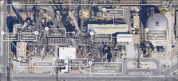
Figure 4. Aerial view of the CF Fertilizer Ammonia Manufacturing Facility at Ince next to the River Mersey in the UK. The area of the ammonia production component at Ince is around 2.5 hectares. The numbers indicate the various stages in the synthesis of ammonia. The ammonia storage tank has a capacity of 10 000 t (which has an LHV energy equivalent to of 50 GWh).
Download figure:
Standard image High-resolution imageThe CO2 that is produced in the water-gas shift reaction is removed (5) prior to the Haber–Bosch process (9). In most existing ammonia production facilities, CO2 is either vented or used to produce urea. Given the massive global scale of ammonia production and the point source nature of its CO2 emissions, carbon capture is an important opportunity that is relatively straightforward to achieve and would result in a 500 Mt reduction (∼1.2% global) in CO2 emissions. This blue ammonia transition is important for existing ammonia plants. Future plants, however, should be carbon-free with only air and water used as the raw materials. This is discussed further in section 15.
Concluding remarks
In ammonia production, which is the principal industry in today's fossil-fuel based hydrogen economy, it is a paradox that hydrogen itself is only fleetingly present. It is incongruous that, while 182 Mt of ammonia are manufactured annually and ∼20 Mt yr−1 are transported across the oceans, hydrogen, in its eponymous economy, journeys a few hundred meters for less than half an hour. The durations and distances are similar in the refining of oil which together with ammonia accounts for ∼90% of the current usage of hydrogen. Although the 2023 annual production of hydrogen headlines at ∼80 Mt, the cumulative global yearly usage of hydrogen amounts to 134 000 t which represents only 0.17% of global hydrogen production. Hydrogen is widely promoted to be the green fuel of the future and is the eponym for the future green chemical revolution. However, the molecule with its own existing global infrastructure that has the most favorable credentials to eventually displace fossil fuels, for both storage, transportation and utilization, is ammonia.
Acknowledgments
The author wishes to thank Trevor Brown, Executive Director of the Ammonia Energy Association, for mining the databases of the US Environmental Protection Agency to retrieve information about the tonnage and very precise locations of anhydrous ammonia facilities across the United States. I also want to thank my daughter, Anna Di-Lieto, for producing the many extremely informative maps that articulate and reveal the magnitude of the prevalence of ammonia facilities across the United States. I also wish to thank Paul Sharp and Nicolas Cook, from CF Fertilisers UK, for explaining in detail the processes involved in the production of ammonia from natural gas, water and nitrogen and, in particular, to chart out the short lifetime and distance of travel of hydrogen before ammonia is stored, transported and used for fertilizer production.
3. Overview of current and future opportunities for low-carbon ammonia
Kevin H R Rouwenhorst1,2 and Rolf S Postma3
1Ammonia Energy Association, 77 Sands Street, 6th Floor, Brooklyn, NY 11201, United States of America
2Proton Ventures, Karel Doormanweg 5, 3115 JD Schiedam, The Netherlands
3Stamicarbon B.V., 6135 KW Sittard, The Netherlands
Email: krouwenhorst@ammoniaenergy.org and rolf.postma@stamicarbon.com
Status
Ammonia is currently almost exclusively produced from natural gas (72%) and coal (22%), following the Haber Bosch process, with heavy fuel oil and naphtha accounting for the remainder [16] This fossil-based ammonia is generally termed grey ammonia. Hydrogen production typically consumes around 95% of the total energy required for ammonia production [16]. The decarbonization of ammonia production is dominantly focused on decarbonizing hydrogen production.
Decarbonization can be achieved (1) through carbon capture of emissions from fossil-based hydrogen production, or (2) through and net zero-carbon hydrogen production methods [17]. An overview of ammonia production pathways is shown in figure 5. The preferred method for decarbonization depends on local resources and incentives as well as the envisioned production capacity [18].
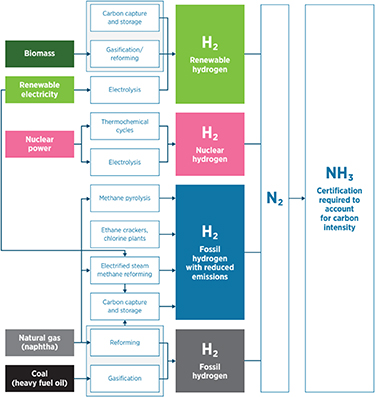
Figure 5. Production pathways of ammonia from various feedstocks. Reproduced with permission from [17]. © IRENA 2022.
Download figure:
Standard image High-resolution imageBlue ammonia is a term frequently used for ammonia produced from fossil fuels, where a significant part of the CO2 emissions are mitigated. It should be noted that the net CO2 emissions can vary depending on the carbon-capture rate in the process, e.g. capturing just the concentrated CO2 from the hydrogen production for the ammonia loop, or also the more dilute CO2 flue gas. Furthermore, the carbon intensity of the fossil feedstock prior to the ammonia synthesis plant should be considered, for example scope 2 and scope 3 emissions from natural gas extraction and transport.
Thus, the carbon intensity of the produced 'blue' ammonia can vary strongly. Therefore, color coding should not be taken as the sole indicator, but rather the carbon intensity and other sustainability indicators. Therefore, transparent frameworks for Life Cycle Assessment are required to certify the carbon intensity of the produced ammonia [17].
Green ammonia is the term used for ammonia that is produced from renewable energy sources, i.e. renewable ammonia, such as solar PV, wind or hydropower coupled with water electrolysis for renewable hydrogen production. Upon combining renewable hydrogen with atmospheric nitrogen and compressing the mixture to 100–450 bar, ammonia can be synthesized via the Haber–Bosch process. An alternative for zero-carbon electricity (and heat) is nuclear power, which is generally termed pink ammonia.
Another pathway for producing renewable ammonia is from circular biomass, biogas, and solid waste. As biomass contains carbon, it can be utilized to produce hydrogen together with CO and CO2 in a process analogues to fossil fuel-based route. This can be beneficial for renewable urea production, which requires carbon oxide as reactant. Biogas can be blended with natural gas in steam methane reformers (SMRs) and autothermal reformers (ATRs) in existing natural gas-based ammonia plants. Similarly, biomass and solid waste can be blended with coal in gasifiers in existing coal-based ammonia plants.
Current and future challenges
About two thirds of CO2 is typically captured in existing natural gas-based NH3 plants with SMRs. However, the remaining one third is in the flue gas at low concentrations and thus at high carbon capture cost. It should be noted that captured CO2 from NH3 plants is currently mainly used for producing urea (CO(NH2)2), which accounts for 55% of current NH3 usage [19]. This CO2 from urea is short cyclical and eventually emitted into the atmosphere upon urea usage, and does not result in a net CO2 emission reduction. For this, permanent CO2 sequestration via carbon capture and storage (CCS) is required. Furthermore, sector coupling with for instance steel production can allow for decreasing the net carbon footprint of the CO2 emitted during urea utilization. However, this raises the question how the CO2 emissions should be calculated and allocated.
Fossil feedstock for ammonia synthesis also has emissions upstream of the ammonia production plant, such as methane leakage during natural gas extraction. This means the supply chain to the ammonia plant must be decarbonized with best practice technologies and procedures.
Renewable ammonia plants are announced at locations with the best renewable resources. However, renewables such as solar and wind are fluctuating electricity sources, implying the ammonia plant must be oversized to meet the required production capacity and be able to operate highly flexibly. In general, electrolysis-based ammonia plants have a higher upfront cost than fossil-based ammonia plants. This is due to the electricity generation that needs to be built together with the ammonia plant, typically accounting for over half the investment required [17]. Alternatively, a power or hydrogen purchase agreement can be closed with a renewables developer which provides electricity for the ammonia plant. This shifts the electricity cost from a capital expenditure (CAPEX) to an operational expenditure for the ammonia plant operator.
The ideal locations for renewable ammonia plants must be identified, not only based on the optimal renewable electricity profile for the ammonia plant, but also on societal acceptance and favorable legislation. The availability of water is another issue that must be taken into account. Consequently, most renewable ammonia projects that have been announced ae located near the sea or a freshwater source.
Electrolysis-based ammonia plants will see a shift in production location from the traditionally fossil feedstock rich locations to more disperse renewables-optimal sites, which will allow certain regions to become self-sufficient in fertilizer production. The absence of carbon in the ammonia synthesis will require a shift from urea as most common fertilizer, or an available circular carbon source for urea.
Nuclear power (and heat) has its specific sets of challenges. Firstly, the electricity cost of existing nuclear power is typically too high to be utilized for electrolysis [20]. Furthermore, the perceived risk of nuclear power generation and nuclear waste production imply its introduction is not accepted in all locations. Lastly, current nuclear power plants typically have a capacity around 1 GW, while electrolysis capacity is typically orders of magnitude smaller, implying a size mismatch.
It is likely that trade of low carbon ammonia will initially be point-to-point, while a more global market will be established at a later stage. It remains uncertain whether a cost premium will be acceptable for low carbon ammonia and if so, how the premium will need to be determined.
Advances in science and technology to meet challenges
Fossil-based ammonia production, and specifically the hydrogen production, can be decarbonized along various pathways. Existing SMRs can recycle part of the hydrogen product to the burners, thereby decreasing the amount of CO2 produced in the flue gas. Alternatively, ATR can be utilized as a substitute for SMR, especially in large-scale plants [18]. ATR combines hydrogen production and natural gas combustion inside the reactor, implying all CO2 will be concentrated and can be easily removed. Novel technologies for natural gas processing include electrified steam methane reforming [19], e.g. the gas-fired heating is replaced by electric heating, and methane pyrolysis, where methane is split into hydrogen and solid carbon [20].
Fluctuations in renewable energy profiles can be accounted for with (1) energy storage buffers and/or ammonia or hydrogen storage, (2) firming with a stable electricity, and (3) more flexible ammonia synthesis loops [17], as shown in figure 6. The most economic design is often a compromise between these three strategies. Energy storage buffers include e.g. (flow) batteries to smoothen solar and wind peaks, ammonia storage tanks or hydrogen storage in high pressure vessels or salt caverns. Hydrogen storage can be combined with a hydrogen fuel cell for electricity generation [21] and stable electricity sources used for firming include the grid, nuclear, geothermal or hydropower. The latter was the electricity source used in the past for renewable ammonia production [22]. High temperature nuclear reactors offer a further option as heat may be utilized for steam electrolyzers, decreasing the electricity demand for hydrogen production. Flexible ammonia synthesis loops designed for renewable feedstock can operate down to 10%–30% ammonia outlet capacity [23, 24]. It should be noted, however, that a reduction in load factor of the ammonia synthesis loop results in a higher relative energy cost.
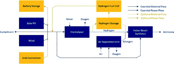
Figure 6. Conceptual diagram of renewable ammonia production including storage buffers. Reproduced from [21]. CC BY 3.0.
Download figure:
Standard image High-resolution imageHydrogen certification schemes are currently set up, based on established LifeCycle Assessment methodologies to estimate carbon intensity, as well as the Sustainable Development Goals. These schemes allow for harmonized trade between jurisdictions. Similar schemes are being developed for certifying ammonia, although these are not yet ready or widely accepted at the moment.
Concluding remarks
Decarbonization of ammonia production is possible with commercially available and proven technologies, such as CCS from hydrogen production, low carbon electricity coupled with water electrolysis, and biomass or waste gasification. Existing low carbon technologies should be implemented today where feasible. Innovative technologies can be implemented at a later stage.
Existing plants may require a combination of low carbon technologies to decarbonize. For example, an SMR-based plant can be decarbonized by replacing part of the natural gas feedstock with biogas, by capturing and storing the CO2 produced, and by replacing part of the hydrogen production with electrolysis. New-build plants can be designed for flexible load operation, to address the issue of fluctuating solar and wind resources, while storage buffers may still be required.
As ammonia takes off as a zero-carbon energy vector, renewable ammonia production in locations with the best solar and wind resources may scale-up to renewable energy hubs with tens of GW upstream solar and wind capacity. This is an order of magnitude bigger than the largest fossil-based ammonia production sites.
Acknowledgments
The authors acknowledge discussions with colleagues at the Ammonia Energy Association, Proton Ventures, and Stamicarbon B.V.
4. Green technologies: low temperature electrolysis (alkaline, PEM), high temperature electrolysis (SOEC), integrated H2, N2 production
John Bøgild Hansen
Topsoe, Haldor Topsøe Alle 1, 2800 Kgs. Lyngby, Denmark
Email: jbhenator@gmail.com
Status
Ammonia is carbon free and can be produced from air, water and renewable electricity by electrolysis. It is easily liquefied and its relatively high energy density of 3.53 MWh m−3 makes it an attractive energy vector for sustainable energy scenarios compared to the use of hydrogen.
Ammonia production via low temperature electrolysis for hydrogen manufacturing and cryogenic air separation for nitrogen supply was practiced worldwide before the advent of modern, natural gas based plants using steam reforming for ammonia synthesis gas production. Operating experience from such a plant based on alkaline electrolysis using hydropower is described in reference [25].
Norsk Hydro operated two plants at 160/165 MW capacity based on their own alkaline electrolyzer design. The Faradaic efficiency is given as 98% at start, degrading by 1% absolute every 4 years. Cell voltage also increased from 1.67 V/cell at the start to 1.8 V after 4 years. Overall energy consumption is stated to be 10 MWh Mt−1 ammonia, including power for air separation (1%) and Haber–Bosch synthesis (7.5%). The power required for the electrolyzer unit was 4.4 kWh Nm−3 H2 as DC power, e.g. ignoring transformer losses. In figure 7 are shown the mass and energy flows for an alkaline 1000 ton per day plant [26].

Figure 7. Overview of low temperature electrolysis based ammonia production. Reprinted from [26], with the permission of AIP Publishing.
Download figure:
Standard image High-resolution imageLow temperature PEM based electrolysis is an established technology that can also be used and is better suited for intermittent and low-load operation as will be required for direct coupling with wind or solar renewable power. PEM electrolyzers are also operating at higher current densities than alkaline so the footprint will be reduced [27, 28].
SOEC operates at 700 °C–850 °C and offers much better energy efficiency at 7.7–7.9 MWh ton−1 ammonia due to favorable thermodynamics and the fact that they use steam instead of liquid water. Part of the steam can be provided by utilization of the ammonia synthesis reaction heat [29, 30].
The nitrogen required for ammonia synthesis is manufactured by air separation. Cryogenic separation is the preferred choice for large capacities as they are energy efficient albeit very expensive. The nitrogen required for 1 ton of ammonia requires an energy input around 200 kWh [31]. Cryogenic plants do, however, not scale well at smaller capacities (scaling exponent close to 0.5). For smaller scale, decentralized plants pressure swing adsorption or membranes will be preferred but they are less energy efficient requiring 300–400 kWh per ton of ammonia for the nitrogen production [31].
Current and future challenges
Electrolysis for green ammonia production will, in the majority of cases, entail coupling to intermittent renewable power sources. This in turn puts an additional emphasis on bringing down the CAPEX. This can be accomplished by increasing the current density (A cm−2) provided that lifetime is not unduly compromised. Long lifetimes of many years have been demonstrated for classical alkaline electrolysis. The prospects for PEM-based systems looks encouraging. Degradation rates for SOECs have improved dramatically lately but challenges with, for instance, agglomeration of nickel in the fuel electrode remains. SOECs have, however, a wide temperature operation window, which can be used to counteract ageing [32, 33].
Robustness is as equally important as durability. This means resilience with respect to operational upsets resulting in off-design conditions with respect to electrical, temperature and/or mechanical stresses. Other aspects include resistance or mitigation of poisons in the feedstocks.
Minimizing cross-over of reactants, which represent a loss of Faradaic efficiency and limit the minimum operation point because explosion limits can be exceeded, is major challenge for alkaline electrolyzers and to some extent for PEM especially at higher pressures.
Mechanical compression of hydrogen is less efficient than electrochemical within the electrolyzers. As ammonia synthesis is operating at pressures preferably above 100 bar, it is beneficial to operate the electrolyzers at elevated pressure. Alkaline electrolysis has successfully been achieved at 30 bar g and PEM electrolysis at much higher pressure. Pressurized operation of SOEC is under development. For all three technologies elevated pressures means increased demands on durability.
From above discussion, it is evident that more than 90% of the energy input for an electrolysis-based ammonia plant is used for the production of hydrogen. Improvement in the Haber–Bosch synthesis would thus only have a minor impact, but for alkaline as well as PEM electrolysis there is room for improvement of efficiency by lowering the different internal resistance. However, for both technologies the possible improvements are limited by the fact that water in liquid form is used. Accordingly the heat of evaporation has to be supplied in the form of electricity to the stacks (approximately 0.5 kWh per Nm3 of hydrogen or 1/6 of the LHV). SOEC electrolyzers use steam, which can in part be provided by use of the reaction heat from the ammonia synthesis plant so that >99% efficiency (LHV basis) can be achieved and has been demonstrated in practice.
With respect to PEM electrolysis the most important challenge is to find and acceptable substitute for iridium as an active oxygen electrode.
Advances in science and technology to meet challenges
The challenges for all electrolyzer technologies are related to the trade-offs realized when trying to simultaneously optimize CAPEX, efficiency and durability.
For alkaline electrolyzers, the search for improved nickel electrode catalyst have intensified in order to increase surface area and activity so that both efficiency and current density can be improved.
For PEM electrolyzers, the most important problem to solve is to optimize the oxygen electrode, where only iridium, at present, can be used. Iridium is a very scarce noble metal with a yearly production of only around 10 metric tonnes per year [34, 35].
For SOECs, improved electrodes could be used to lower the operating temperatures further and also improve lifetime. Better morphology and new materials for both cathode and anode are relevant challenges.
The diaphragm is an important focus point for alkaline technology. Reduced thickness would improve efficiency. Another challenge would be to improve the PTl (porous transport layer) by, for instance, zero gap electrodes in order to improve mass transfer.
PEM electrolyzers use very expensive PTLs with platinum coated titanium. There is limited scope in reducing membrane thickness which are probably close to the optimum.
A better understanding of the mechanism(s) behind nickel agglomeration degrading SOEC performance would facilitate the search for solutions.
All electrolyzer technologies are sensitive to minute amounts of poisons or contaminants from the feedstock or construction materials including the raw materials for the stack. Efficient clean up materials will increase durability considerably and/or reduce balance of plant (BOP) costs.
Another common theme will be to increase cell and stack sizes leading to economy of scale savings in the BOP.
There are also room for improvements in manufacturing the stacks by automation and streamlining supply chains. Power supply units are expensive and incur efficiency losses.
Finally research into optimized and safe operating procedures is especially relevant given that intermittent operation and integration with downstream ammonia production will become of paramount importance.
Concluding remarks
Ammonia has emerged as an interesting energy vector in the transition to a sustainable carbon-free energy. IEA foresee in their net-zero carbon scenario for 2050 that 74 Mtonnes ammonia is used for electricity production and 250 Mtonnes for transport. IEA concludes that electrolysis becomes competitive with natural gas based production with CCUS at electricity prices in the range of USD 15–50 MWh−1 for ammonia, on the assumption of gas prices of USD 3–10 GJ−1 provided electrolysis CAPEX decrease by 50% and efficiency increases by 15%.
The targets are within reach to address the challenges discussed above. The scale and speed required for the deployment of electrolysis based green ammonia technology to take place is daunting and will require massive scientific, technological and financial innovations. An exemplar is the use of ammonia for shipping has attracted significant interest. If 30% of the forecasted demand for shipping fuels in 2050 was to be met by ammonia, an extra production capacity of 150 million tons per year would have to be installed. Approximately 400 GW of renewable power would be required to sustain this production if based on alkaline electrolysis with an energy consumption of 10 MWh MT−1 ammonia [36].
5. Redefining the Haber–Bosch process for green ammonia production
Laura Torrente-Murciano and Collin Smith
Department of Chemical Engineering and Biotechnology, University of Cambridge, Philippa Fawcett Drive, CB3 0AS Cambridge, United Kingdom
Status
The global ammonia production in 2022 is ∼180 million tons per year and is used primarily for fertilizer purposes, which, in turn, is reckoned to provide food for over 50% of the world's population. Currently, ammonia is produced through the Haber–Bosch process using fossil fuels as feedstock and energy source (mainly natural gas, but also coal and oil). This over-100-year-old technology, has been highly optimized and integrated, and is close to reaching its thermodynamic efficiency [37]. It is designed to operate continuously 24/7 and benefits from economy of scale with typical ammonia plants producing ∼2000–4000 tonnes of ammonia per day. However, it is only an optimization for extracting hydrogen and energy from fossil fuels. Industrial ammonia production today consumes ∼2% of the global energy demand and is responsible of ∼1.5%–2.0% of the overall CO2 emissions.
Currently, the thermo-chemical production of ammonia is the only feasible route for industrial ammonia production due to the high reaction rates and hydrogen utilization in comparison to electrochemical or plasma routes [38, 39]. However, its future relies on electrification, where the process will be exclusively powered by renewable energy using air and water as feedstocks. In the conventional Haber–Bosch process, hydrogen and heat are produced by steam-reforming of fossil fuels, followed by their use in the ammonia synthesis step (Haber–Bosch loop) (figure 8(A)). Electrification requires the decoupling of these two steps, with hydrogen being produced by the electrolysis of water using renewable energy (or alternative sustainable sources such as reforming of biogas) (figure 8(B)). This transformation opens up opportunities for the design of new processes, the re-development of the Haber–Bosch loop and the need for new optimization and integration strategies.
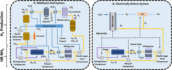
Figure 8. Schematic diagram of (A). A typical conventional methane-fed Haber Bosch process and (B). An electrically powered alternative. Hydrogen and ammonia production stages are separated for illustration purposes to identify similitudes and differences between both technologies. Yellow lines are process gas, dark blue lines are water/steam, light blue lines are air, purple lines are ammonia, and dashed lines are electricity. Reproduced from [37]. CC BY 3.0.
Download figure:
Standard image High-resolution imageThe successful development of green ammonia synthesis processes will deliver, in the short term, green fertilizers to provide food security in a sustainable manner. Equally important and with a potential higher impact, it will deliver a unique solution for the chemical long-term storage of renewable energy, mimicking the way that fossil fuels store energy but in a carbon-free molecule [40]. The high energy density of ammonia at mild conditions will trigger an international trading of renewable energy. It will also witness a multitude of uses of ammonia as a direct fuel to meet our transport and heating demands [41], and via its decomposition, as a source of ammonia-hydrogen fuel blends and pure hydrogen itself.
Current and future challenges
The production of green ammonia has been demonstrated at an industrial scale for more than a century. Indeed, the first industrial production of green ammonia was developed in Italy in 1921. Other green ammonia plants followed around Europe (e.g. Spain, France, Norway, Sweden) and around the World (e.g. Japan, Canada and USA) representing approx. 25% of the global ammonia production in 1930 (∼0.5 m tnNH3 out of the total annual global production of approx. 2 m tnNH3) [42]. In all the cases, hydrogen was produced by water splitting using alkaline electrolyzers powered by hydropower in relatively small units (∼300 tnNH3 per day). The onset of cheap and abundant natural gas, the technological development of hydrogen extraction from fossil fuels and the difficulties regarding scaling-up electrolyzers led to their closure by mid 1960 s, based on economic terms.
Current environmental pressures, the desire for energy independency as well as improvements in electrolyzer efficiency and cost reduction has re-initiated the interest in green ammonia production. However, the increase in ammonia demand creates a need to tap on renewable energy sources beyond hydropower. This is further exacerbated if green ammonia is to play a role as carbon-free energy vector in the future energy transitions where its production scale is expected to increase 5–10 times. Although hydropower still represents the largest proportion of renewable energy, we are currently witnessing fast developments in solar and wind sources due to their reduced cost, lower environmental impact and the larger array of suitable locations [22]. However, solar and energy power capacities are intermittent, strongly dependent to the location and distributed.
The production of 1000 tn d−1 of green ammonia requires 176.5 tn d−1 of green hydrogen. Assuming the bulk figures of the need of ∼60 MWh/tnH2 (using a typical commercial alkaline electrolyzer) and the land requirements of 0.50 MW/hectare when using solar energy and 0.06 MW/hectare when using wind energy and a typical capacity of 20% and 40% for solar and wind energy respectively [43], one can estimate the bulk land requirements for future green ammonia production. Thus, a green ammonia plant with a production capacity of 1000 tnNH3 d−1 will require a land extension in the order of at least 4400–18 400 hectares, equivalent to 4%–17% of the area of London or ∼6000–26 000 football pitches, when using solar and wind power respectively. It is important to note that this production capacity is less than half the average production capacity of a conventional ammonia plant.
Advances in science and technology to meet challenges
This analysis leads to three options:
- i.decentralized electricity production with transmission to centralized plants,
- ii.decentralized hydrogen production where a number of renewable energy installations produce hydrogen locally, transported (e.g. by pipelines) to a centralized ammonia production plant and
- iii.decentralized small-scale ammonia production with plants with small capacities.
The first option might consider electrified ammonia plants connected to the grid, assuming that the grid is sufficiently decarbonized. It requires large investments in grid infrastructure as well as ensuring that remote renewable energy installations have connection to the grid. An alternative is the use of private connections. The second option of decentralized hydrogen production will facilitate the deployment of green ammonia plants with large capacities (i.e. similar to the current ones) while the third option opens a wide range of opportunities for localized green ammonia production, eliminating the potentially elevated cost of transport for both, hydrogen and ammonia.
In all three cases, the economics are skewed by the current cost of renewable energy and electrolyzers [44]. Technological breakthroughs are urgently needed for more efficient hydrogen production with electrolyzers able to use low purity water (e.g. desalinated water) to avoid pressures on water accessibility [45]. In addition, decoupling the hydrogen and ammonia production steps requires new process integration strategies. Heat integration between different process steps are particularly relevant to maximize the overall energy efficiency. It is important to note that conventional heat integration approaches might fail in these enterprises as some of the process steps may not be co-located in space and/or time, as discussed above.
The lack of a continuous energy supply from renewables, in contrast to fossil-fuel based energy supply today, presents a number of challenges. For electrified ammonia plants connected to the grid (option i.), it will be translated in weather-dependent short-term variations of the electricity price. For decentralized hydrogen or ammonia production options (ii. and iii. above), it will rely on the use of energy buffers such as batteries and/or hydrogen storage to cope with short-term energy supply variations. The dependency on hydrogen buffers is further exacerbated by the challenges of coping with the seasonal variations of renewable energy which can account to >20% of the levelized ammonia cost [44].
A highly attractive alternative to the options discussed above is the development of flexible ammonia synthesis technologies with ramping capabilities able to respond and align as much as possible to the renewable energy production profiles. The development of low temperature, non-noble metal based catalysts will certainly contribute towards this endeavor. However, greater impacts can be achieved when considering a holistic process development [46]. For example, replacing ammonia separation using condensation by absorption in the synthesis loop removes the need for high pressures (∼150 bar) of the current process, opening the door to mild pressure operation (∼20–30 bar) [47], directly enhancing its flexibility to ramp capacity (figure 9(b)). A more innovative approach is the integration of the ammonia synthesis and separation steps into a single-vessel recycle-less process [48, 49] (figure 9(c)). This inherently safe process is able to perfectly mimic the hydrogen production profile with no possibilities of leading to run-away reactions. This approach however, will lead to a low capital utilization.
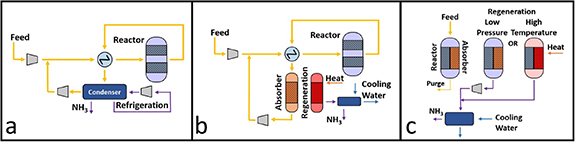
Figure 9. (a) Conventional Haber–Bosch ammonia synthesis loop, (b) replacement of ammonia via condensation by absorption opening the door to mild pressure operation and (c) single-vessel recycles process where the synthesis and separation steps are integrated. Reproduced from [37]. CC BY 3.0.
Download figure:
Standard image High-resolution imageConcluding remarks
The synthesis of green ammonia exclusively powered by renewable energy and using air and water as feedstock has been technologically feasible since the onset of this industrial process. However, its economic feasibility away from subsidies and carbon credits relies on technological innovations able to minimize the detrimental effects of the intermittent nature of renewable energy. Amongst them, the development of nimble processes able to operate away from steady-state following the energy supply profile will be a paradigm shift in the chemical industry. Similarly, distributed small-scale modular ammonia production systems will transform the well-established economy-of-scale while avoiding the need of transport and providing cost control over market fluctuations. In all cases, novel optimization tools, safety and integration strategies are required to tailor the design and operation to location and needs. As a result, the successful development of green ammonia processes will not only lead the way for the electrification of the chemical industry on what is called Power-to-X but most importantly will enable the long-term storage and trading of renewable energy to open the door to a new green energy landscape.
Acknowledgments
The authors would like to thank the UK Engineering and Physical Science Research Council (EPSRC—Grant Number EP/X016757/1) and Breakthrough Energy for the Explorer grant Ammpot for funding.
6. Electrochemical & photochemical ammonia synthesis/electrochemical nitrate reduction
Douglas R MacFarlane1, Alexandr N Simonov1, Andrew Medford2, Marta Hatzell2
1School of Chemistry, Monash University, Clayton, Victoria 3800, Australia
2School of Chemical & Biomolecular Engineering, Georgia Institute of Technology, Atlanta, GA 30310, United States of America
Email: Douglas.macfarlane@monash.edu, alexandr.simonov@monash.edu, ajm@gatech.edu and marta.hatzell@me.gatech.edu
Status
Electrochemical reduction of N2 to ammonia is an attractive process that would ideally consume only N2, protons from the electrolyte and electrons at the cathode, while at the same time carrying out water oxidation at the anode. Thermodynamically, the N2 + 6H+ +6e−
 2NH3 process occurs at a more positive potential than proton reduction (2H+ + 2e−
 H2), such that it should be possible without interference from hydrogen evolution. Hundreds of research reports have been devoted to this nitrogen reduction reaction (NRR), exploring a wide variety of electrocatalysts [50]. However, the overpotentials required are invariably sufficient that H2 production does occur. The Faradaic Efficiency (FE = the fraction of charge applied that results in ammonia) then becomes an important metric of the effectiveness of the electrocatalyst. Unfortunately, there are very few reports of FEs >50% and most are <20%. Even more challenging, the rates of the reaction per unit area, measured in mol(NH3) s−1 cm−2, are typically very small; so small that interference from other reducible N-compounds, including nitrates and NOx
gases, becomes a concern. In recent years the field has recognized the need to include quantitative 15N2 reduction experiments to verify the source of the nitrogen [51]. Tests with a small, fixed volume of nitrogen is another approach to prove the genuine nature of the NRR. The net result is that a number of the more substantial claims of success with aqueous NRR are being refuted [52] and the vast bulk of the reports are considered to be too low in yield rate to be practical [50], even if it can be shown that they do represent genuine NRR.
H2), such that it should be possible without interference from hydrogen evolution. Hundreds of research reports have been devoted to this nitrogen reduction reaction (NRR), exploring a wide variety of electrocatalysts [50]. However, the overpotentials required are invariably sufficient that H2 production does occur. The Faradaic Efficiency (FE = the fraction of charge applied that results in ammonia) then becomes an important metric of the effectiveness of the electrocatalyst. Unfortunately, there are very few reports of FEs >50% and most are <20%. Even more challenging, the rates of the reaction per unit area, measured in mol(NH3) s−1 cm−2, are typically very small; so small that interference from other reducible N-compounds, including nitrates and NOx
gases, becomes a concern. In recent years the field has recognized the need to include quantitative 15N2 reduction experiments to verify the source of the nitrogen [51]. Tests with a small, fixed volume of nitrogen is another approach to prove the genuine nature of the NRR. The net result is that a number of the more substantial claims of success with aqueous NRR are being refuted [52] and the vast bulk of the reports are considered to be too low in yield rate to be practical [50], even if it can be shown that they do represent genuine NRR.
Electrochemical N2 reduction is not limited to aqueous media. A number of groups have investigated a lithium-mediated reaction (figure 10) that offers potential for a high-rate process [53–56]. The lithium cation acts effectively as a redox-catalyst in this process, being regenerated in each cycle.
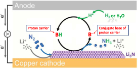
Figure 10. Schematic of the Li-mediated nitrogen reduction process. From [55]. Reprinted with permission from AAAS.
Download figure:
Standard image High-resolution imageRecent advances [55, 57] have brought the FE of this approach to nearly 100% and rates to values (ca 0.5 μmol s−1 cm−2) close to the U.S. Department of Energy targets for NRR (90% FE and ca 1 μmol s−1 cm−2). Another important feature demonstrated in these recent reports is the ability of the process to cycle on and off as required. The downside of this approach is the overall energy efficiency, which is limited to around 25% by the lithium mediator. Improvements will no doubt emerge from investigations of alternate mediators.
High temperature electrochemical cells are also under development for ammonia production, based on hydrogen oxidation as the anode process. A range of reports have presented solid oxide electrolyte cells for ammonia electrosynthesis under such conditions [58]. Once again, the yield rates reported are low to the extent that the genuine nature of the process remains questionable.
An alternative possible approach is direct photocatalytic ammonia synthesis from N2 and H2O, but the ammonia yields demonstrated are significantly below electrochemical NRR. Nevertheless, research on photocatalytic ammonia synthesis is rapidly growing and it is critical for this field also to adopt rigorous protocols to eliminate false positives.
Finally, an indirect pathway to ammonia has been suggested that involves plasma-assisted N2 oxidation to oxidized forms of nitrogen (NOx ), followed by the selective electroreduction of the latter to NH3 [59]. While the second electrochemical step of this approach is clearly feasible and is well established [60, 61], energy-efficient N2 to NOx conversion is yet to be achieved.
Current and future challenges
Although non-aqueous solvents are capable of dissolving much higher amounts of N2 than water, the achievable concentrations are still challengingly low. To overcome this, recent reports have moved to moderately elevated N2 pressures around 15 bar. Notably, such pressures are required to liquify ammonia at ambient conditions and can be expected to be present in other parts of the system. Nonetheless, there remains an important to goal to reduce the operating pressure to ambient, in order to simply the technology of these cells.
The electrochemical reduction of oxidized forms of nitrogen (NOx RR) [62–64], mentioned above, derived from plasma-assisted N2 oxidation [59] holds promise. Moreover, nitrate and NOx gases are common pollutants in groundwater and the atmosphere, and electrochemical NOx reduction has been studied to treat waste streams for more than half of a century [60, 61]. Nonetheless, challenges remain if the resulting ammonia is to be used as an energy carrier. First, since the nitrate is present in an aqueous setting, hydrogen evolution is a competing reaction, and its suppression is largely accomplished through tuning the pH to alkaline conditions. However, design of catalyst and microenvironments to suppress hydrogen production is desirable, potentially through electrolyte engineering [65]. Even more promising is design of effective NOx RR catalysts that enable the process at potentials where H2 evolution is not possible [64]. Another challenge is that nitrate found in waste streams is often accompanied by contaminants, which can poison the catalyst; pretreatment processes will be required. Design of durable and stable catalysts is thus an important direction in the field of NOx RR [66], focusing on low-cost materials, as well as low catalyst loadings [67]. On the systems level, since nitrate is present at dilute concentrations both in nature and in the plasma N2 oxidation process, identifying the minimum concentration necessary for efficient reduction remains a critical discussion.
An alternative involves direct photocatalysis of the NRR or NOx RR; this could allow direct harnessing of solar resources that are plentiful in areas where ammonia is currently scarce (figure 11) [68, 69]. The challenge here is that both upstream and downstream separations are likely required to deliver concentrated ammonia from a low-yield process, potentially negating the low-cost advantages of photocatalysis over electrocatalysis. This scale-up challenge is particularly pertinent if ammonia is to be used as an energy carrier, since large volumes and high purity will be required. However, for agricultural applications solar-to-ammonia efficiencies below 1% may be practical if low-concentration ammonia can be directly utilized [69].

Figure 11. Comparison of global distribution of solar energy, farmlands, and Haber–Bosch plants. The average daily solar flux (top) compared to the location of Haber–Bosch plants (black dots) and distribution of farmland (bottom). Reprinted from [69], Copyright 2019, with permission from Elsevier.
Download figure:
Standard image High-resolution imageAdvances in science and technology to meet challenges
Requiring substantially higher energy inputs than the Green H2 + HB route, the major remaining issue in the alternative routes to ammonia, either through electrochemical N2 reduction or N2 oxidation + NOx electro/photoreduction, is energy efficiency; this is especially true of the latter. However, the rapidly falling price of renewable electricity, especially in dedicated installations, will have an impact on the significance of this energy input-cost. Technoeconomic analyses are being carried out by a number of groups to understand the energy versus capital cost factors in both cases. It is likely that the outcome in terms of overall cost competitiveness versus traditional ammonia production will express a strong regional component, reflecting the balance of renewables available and the relative value of the ammonia or fertilizers produced.
Establishing molecular-scale insights into the active sites and reaction mechanisms are instrumental to the discovery of practical processes for ammonia synthesis. Towards this end, the use of advanced in situ and operando spectroscopies along with predictive theoretical models can provide valuable insights. Similarly, advanced quantum mechanical modelling and molecular dynamics simulations enable a deeper understanding of molecular-level events. In other words, funding bodies must not underestimate the significance of pure fundamental research, which is the only pathway to innovation and new technologies that will support energy futures. Translation of fundamental concepts to the practical domain will require closer integration between process, reactor, and catalyst design, supported by detailed technoeconomic studies that can help identify quantitative performance targets and operational conditions under different use cases and economic scenarios. The resulting practical insights will help guide the development of testing conditions and performance metrics for process evaluation and can help move renewable ammonia synthesis out of the lab and into the field.
Concluding remarks
Sustainable N2 activation processes based on either electrochemical or photochemical energy input clearly hold the promise of producing ammonia and fertilizers at a distributed scale, finding application in the first instance in the agricultural sector. Efforts to commercialize these technologies are underway in a number of start-up companies [70]. Economies of scale and further significant developments in energy cost in the future will ultimately determine the conditions under which these technologies become attractive versus a Green H2 + Haber Bosch process. Direct cost comparisons are likely to only represent part of this calculus since security of supply has also become a major factor in many regions. Ultimately, we expect that a variety of (photo)electrochemical and other processes for electrifying ammonia synthesis will play a role, with the viability of various options being determined by the wide geographical variations in energy cost, feedstock supply, and ammonia demand. Nevertheless, future development and implementation of these new technologies and any planned mitigation steps must be supported by rigorous assessment of their potential to impact the, already significantly affected, natural N-cycle in the global eco-system [71].
Acknowledgments
The material based upon work by A J M was supported by the National Science Foundation under Grant No. 1943707. D R M and A N S acknowledge the financial support from ARC (FT200100317; DP200101878).
7. Ammonia storage, transportation and delivery: an integrated global perspective
René Bañares-Alcántara and Nicholas Salmon
Department of Engineering Science, Oxford University, Oxford OX1 3PJ, United Kingdom
Email: rene.banares@eng.ox.ac.uk and nicholas.salmon@worc.ox.ac.uk
Introduction
The promise of ammonia as an energy source primarily originates from the ease with which it can be stored and transported compared to hydrogen. The two most important physical properties which enable this behavior are its density (in the liquid state, it holds around 120 kg m−3 of hydrogen, whereas liquid hydrogen holds only 71 kg m−3)—and its boiling point (−33 °C at atmospheric pressure, as opposed to −252 °C for hydrogen) [72]. Therefore, compared to hydrogen, it is much easier to get ammonia into the liquid state, to hold it in the liquid state, and to transport it in that state.
Despite these favorable properties, the transport costs of ammonia exceed those of conventional fossil fuels—on an energy density basis, it holds only 3.5 kWh l−1, which does not compare favorably to crude oil or its derivatives (between 9 and 11 kWh l−1) or even liquid natural gas (6.5 kWh l−1) [72]. Therefore, while ammonia may in many cases be preferable compared to hydrogen as a vector for renewable energy, the problem of ammonia supply chains is a significantly more expensive one than that encountered using conventional fuels only. Even though production costs tend to dominate in comparison to transport costs, the supply chain is still deterministic of the best ammonia production site to fulfil a certain demand, because over medium distances (∼5000 km), the transport cost may exceed the difference in production costs between two prospective supply locations (see figure 12).

Figure 12. Examples of production and transport costs from potential major suppliers to Hamburg (shown with a red cross), estimated using cost projections for 2030. Blue lines represent marine transport; green corresponds to pipelines. Transport is shown on great circle lines for clarity, but true marine distances are used in shipping cost estimates. Production costs are sourced from [73], with the method updated to use 2030 costs. Transport costs are estimated using the method from [74].
Download figure:
Standard image High-resolution imageFigure 12 demonstrates this principle, comparing five production sites and the associated cost of transport to Germany. Local production is not affordable, with costs even higher than when ammonia is imported a very large distance from Australia. However, it is equally inappropriate to simply select the cheapest production site in Chile, because the transport costs are excessive. Regional production in either Norway or Morocco with short distance transport has a total cost that is around 10% cheaper than imports from Chile.
For that reason, selection of the cheapest transport and storage properties in isolation is to oversimplify a complex problem. Determining the optimal solution for the location of ammonia production facilities, or the design of energy systems more broadly, must factor both local production costs as well as supply chain costs. This will change the nature of global energy trade. Historically, the abundance of fossil-based energy dense fuels created economic incentives for large scale production in low-cost hubs (e.g. the Middle East and the US Gulf Coast), since even very long-range transport of these fuels did not translate into high costs. Moving into the future, transport of chemical fuels will remain a critical requirement for energy system stability, and ammonia will be able to plug some of the gaps left by fossil fuels [75]; however, production will be more distributed, and transport will be more regional, rather than intercontinental, to avoid the very high transport costs which would otherwise accrue in hub-based production [74, 76].
This section has two purposes: firstly, to describe the engineering considerations required for ammonia transport, and secondly to discuss how these and other factors impact the economic case for ammonia export, as opposed to alternative forms of energy storage or production.
Engineering considerations for ammonia transport and storage
Ammonia storage will typically be required at three points in the supply chain: at the production site, at a transit port, and at the usage site. In general, this can be achieved in tanks similar to those widely deployed in the chemicals and energy sectors. A refrigeration unit should be included in order to prevent boil-off that will otherwise occur due to ambient heat transfer. This simple tank design is in stark contrast to the storage of liquid hydrogen, which has historically used gas spheres, which must be very well-insulated to prevent excessive boil-off. Due to the technical challenges of constructing these spheres, they are fairly small in volume; the largest liquid hydrogen sphere in the world holds less than 4% of the hydrogen that can be contained in a large ammonia tank [77, 78]. Ammonia tanks are already used at large scale in the fertilizer industry, and technological development is not required to facilitate the use of these tanks for energy storage.
The role of these tanks in the supply chain varies according to the end-use application of ammonia, and the means of transport under consideration. However, in general, the tank/s at the supply site should be used as buffer(s) to smooth out the variable operation of the green ammonia production facility, which will typically ramp down during periods of low renewable energy production, particularly if the local resource is highly seasonal. Because ammonia storage is reasonably cheap, it will generally be more economical to significantly oversize the tank at the supply site and absorb all variations in the operation of the comparatively expensive ammonia synthesis unit (rather than modulating down otherwise affordable production in periods when the tank is full). Downstream tanks at ports are then required to enable ships to be fully loaded and unloaded at the supply and demand ports respectively.
The only economic mechanism for large scale ammonia transport over land is by pipeline; while road and rail transport are both technically possible, their labor intensity results in very high costs. By contrast, ammonia can be transported in low-cost carbon steel pipelines because it is non-corrosive. These pipelines are already in wide use, particularly in the USA, where over 4500 km have been installed [79]. Having been delivered to ports, ammonia will then be transported via gas carrier; these carriers are already in wide use today, and many more existing ships can be converted to ammonia transport because it has a similar density and boiling point to LPG. Again, this compares favorably to shipping liquid hydrogen, for which commercial scale shipping does not exist. There is a wide range in ammonia ship sizes available, up to a maximum transport capacity of around 80 000 t of ammonia per ship. Very small-scale ships may use a semi-pressurized, semi-refrigerated vessel to keep ammonia in the liquid state, but in general fully refrigerated tanks at atmospheric pressure will be more affordable at export scale. In order for the delivered ammonia to be carbon neutral, the gas carrier itself will need to use some of the ammonia onboard as a fuel; this would cannibalize about 1% of the fuel onboard for a 10 000 km journey, which is roughly the distance from Shanghai to LA [74].
Although pipeline transport is cheap, ammonia shipping has the lowest cost per ton-kilometer for ammonia, averaging around 0.5 USD/t/100 km (including fuel costs for 2022), compared to around 2 USD/t/100 km for pipelines. For an inland journey of 1000 km followed by a maritime journey of 5000 km, this translates into around 25 USD/t [74]. Maritime costs will fall more rapidly than pipeline costs as the fuel cost itself falls. For reference, production forecasts predict that by 2030, production of green ammonia will be achievable for less than 400 USD/t, which will fall to around 250 USD/t by 2050. The fall in transport costs will not be as significant, meaning the fraction of cost associated with ammonia transport will increase as time progresses [28, 76]. The estimates provided here have a high uncertainty: pipeline construction cost will vary significantly in different jurisdictions depending on costs of labor and land, as well as environmental regulations; shipping costs are highly volatile and tend to vary in 3 or 4 year cycles [80].
Economic drivers for transport
Simplistically stated, the economic driver for energy transport using ammonia is a differential in production cost between supply and demand sites which is greater than the cost of ammonia transport. However, the accurate estimate of these costs is complicated by several factors.
Firstly, although the application of ammonia as a dispatchable energy source will sometimes lend itself to supplying a constant demand—exports to Japan and Korea, for instance, which are likely to import energy year round [81, 82]—it will also lend itself to trade on the spot market, in which case much longer distance transport may occur if justified by price spikes. This spot market trading may be used when ammonia is required to correct seasonal renewable energy imbalances [83] or as a source of energy during extended, abnormal periods of low renewable energy generation such as Dunkelflaute (renewable energy droughts), which are forecast to become more common as global warming increases [84].
Secondly, where neither long-distance (> ∼500 km) transport nor long-term (> ∼1 week) storage are required, direct hydrogen consumption will be the preferred end-use application as it avoids the energy inefficiencies of ammonia generation. This will likely lead to the co-production of both hydrogen and ammonia by energy exporters, with cross-subsidization of both chemicals periodically occurring under different market conditions. This may cause transport of ammonia over unexpectedly large distances; although this will not be profitable in all market conditions, producers can insulate themselves against those conditions by switching production to focus on domestic hydrogen rather than the export market. However, it may also change the nature of global trade, reducing the incentive for energy transport. This represents a source of opportunity for least developed countries with high renewable energy potential to house industries that depend on other local resources (where those resources may previously have been sent offshore), e.g. steel and aluminum production.
Thirdly, the main driver of cost differentials in ammonia price between locations is the quality of the renewable resource, but this differential will change as the price of renewable energy falls. In the short term, ammonia produced from predominantly wind is expected to outperform that produced by solar, but the rapidly falling price of solar panels will shift this balance. Falling electrolyzer costs will also benefit solar-driven plants—although the electricity produced from solar PV is usually cheaper than that sourced from even good wind locations, its capacity factor—and therefore the capacity of equipment that depends upon it—is usually lower, meaning the utilization of the electrolyzer is lower at solar sites; this will cease to have a major impact on costs as the electrolyzer itself becomes cheaper.
Assessing the best site will be further complicated as the highest quality renewable resources are consumed, forcing up land prices as different energy sources compete for sites with the best solar irradiation and wind profiles [73]. Over the lifetime of ammonia plants, therefore, two locations between which a significant cost differential exists may find a narrowing or even an inversion of that cost differential which prevents or changes the nature of ammonia trade.
Overall, although the technical challenge of transporting and storing ammonia is a relatively simple one, the economics are highly complex. Making transport and storage decisions requires a specific understanding of the intended end-use, and a sophisticated understanding of the integrated system of ammonia production and transport, which will dictate the economic conditions that determine whether the use of chemical energy vectors is justified.
8. Ammonia to ammonia-hydrogen blends: catalysts, reactors and purity
Joshua W Makepeace
School of Chemistry, University of Birmingham, Edgbaston B15 2TT, United Kingdom
Email: j.w.makepeace@bham.ac.uk
Status
While ammonia synthesis catalysts have been the subject of intensive and broad scientific investigation for decades, the reverse process, the conversion or cracking of ammonia into hydrogen and nitrogen, has received only limited attention. Indeed, many of the historic investigations of the ammonia cracking reaction were with the explicit aim of gaining further insight into the ammonia synthesis process, taking advantage of the milder conditions required to achieve a wide range of ammonia partial pressures [85]. Interestingly, despite this limited research activity, commercial ammonia cracking units have been available for purchase for many years. These units are typically small, producing between several kilograms and over one tonne of hydrogen per day, and are generally designed to generate a reducing atmosphere for metallurgical treatments. A small number of industrial-scale ammonia cracking plants processing between several hundred and over one thousand tonnes of ammonia per day have been operated as part of heavy water production processes [86].
With the advent of heightened interest in the use of green ammonia as a zero-carbon fuel and energy store, ammonia cracking technology takes on new importance. The decomposition of ammonia to release some or all of its stored hydrogen facilitates a variety of energy-based end uses, highlighted in table 2. Complete ammonia cracking enables its utilization in hydrogen fuel cells or the addition of hydrogen to local and national gas grids. Partial decomposition enables more effective combustion of hydrogen-ammonia blends compared with ammonia, which suffers from low flame speeds and a narrow flammability range [40]. Thus, the development of efficient ammonia decomposition technology is a key plank in the effort to realize ammonia's potential tole as a renewable energy trading commodity.
Table 2. Summary of key uses of partially or fully cracked ammonia.
| Power generation technology | NH3 cracked (%) | Key usage | Notes |
|---|---|---|---|
| Polymer electrolyte membrane fuel cell | ∼100 | Hydrogen fuel cell vehicles | Extremely high purity hydrogen required. |
| Hydrogen boiler/appliances | ∼100 | Heating | High purity hydrogen required for gas grid application. |
| Alkaline fuel cell | >90 | Industrial, off-grid, backup power generation | |
| Combustion engine | 0–100 | Marine or other heavy transport | Ammonia-hydrogen blends for improved flame properties, NH3 and NOx emission reduction key issues |
| Gas turbine | 0–100 | Power generation, aviation |
Current and future challenges
Commercial ammonia cracking units, not having being designed with energy uses in mind, are some way from representing an 'off-the-shelf' solution to ammonia decomposition in these extended contexts. Most commercial systems operate at very high temperatures (800 °C–1100 °C) and are not optimized for energy efficiency. There are three key challenges to the optimized implementation of ammonia cracking in the use of ammonia for energy: the development of new active catalyst formulations, the design of reactors for efficient integration with power generation and effective heat transfer, and the implementation of appropriate purification regimes to meet environmental and technical benchmarks.
As mentioned above, commercial ammonia cracking systems often operate at very high temperatures to achieve sufficient ammonia conversion, in part due to the use of nickel-based steam methane reforming catalysts which are not optimized for ammonia cracking. However, ammonia decomposition is thermodynamically favorable above 190 °C (at 1 bar), and lower temperatures of operation will bring advantages relating to improved reactor durability, greater efficiency and an easier integration with waste heat sources such as those provided by combustion exhaust streams. Given the relative paucity of research into ammonia cracking catalysts compared with those for ammonia synthesis, there is significant scope for the development of more active catalyst formulations. While ruthenium and ruthenium-based bimetallic catalysts dominate high activity formulations at low temperature (figure 13), the high cost and environmental impact of this rare metal may limit its broader application [87, 88].
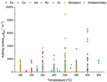
Figure 13. A summary of hydrogen production rates by mass reported for various ammonia decomposition catalysts. Data generated from WHSV and conversion data reported in [88] and associated references.
Download figure:
Standard image High-resolution imageIn designing an ammonia cracking reactor, a key consideration is that the reaction is endothermic (45 kJ mol−1 NH3). This means that energy, equivalent to roughly 12% of the stored energy, must be supplied if ammonia is to be completely decomposed into nitrogen and hydrogen, though this value will of course be lower for reduced cracking levels. This presents a challenge to the design of reactors which can efficiently supply heat to the catalyst bed in order to effectively maintain the reaction temperature, leading to long and thin tubular reaction designs [89, 90]. Many energy systems would favor integrated ammonia cracking and power generation (e.g. in gas turbines), which needs to be factored into future reactor designs.
Finally, control of the purity of the cracked ammonia is critical for applications where trace ammonia could have significant technological (e.g. PEM fuel cells) or safety (gas grid) implications. These circumstances require control of residual ammonia levels down to sub-ppm levels. Furthermore, exhaust emissions of ammonia and nitrogen oxides must be controlled in order to ensure deleterious environmental effects of the use of ammonia are minimized. While there are many well-established approaches to separation of hydrogen from other gases, the need to do so to very stringent requirements in a cost-effective and space-efficient manner remains difficult.
Advances in science and technology to meet challenges
New families of ammonia decomposition catalysts based on metal amides and imides, have been reported in recent years, either as individual catalysts [91–93] or in composites with transition metals [94–96], and are notable for their high activity at modest temperatures without the need for ruthenium. The flexible composition of these materials under active conditions [97, 98], and the presence of key defect sites [94] appears to be key to their activity. The development of catalysts based on iron, molybdenum and cobalt also show exciting promise as alternatives to ruthenium. Further research on the use of advanced catalyst formulations which follow recent progress in ammonia synthesis catalyst development such as bimetallic or two-site catalysts and active catalyst support architectures may prove productive in further enhancing the low-temperature ammonia cracking activity.
The use of simple sorbent-based approaches for removing small residual quantities of ammonia from cracked gas streams have been shown to be effective in meeting the purity benchmark required for ammonia content in hydrogen for PEM fuel cells [99, 100], while metal membranes are favored for simultaneous nitrogen and hydrogen removal at smaller scales where larger pressure-swing adsorption units used in industrial gas separations are not practical. While palladium-based membranes have been used for the production of pure hydrogen for some time, recent development of palladium-coated vanadium membranes has offered a lower-cost approach which has already been applied to ammonia cracking for hydrogen vehicle refueling purposes [101]. Key advances in reactor design combine consideration of ammonia cracking and hydrogen purification, with the development of catalytic membrane reactors which purify the hydrogen stream within the reactor hot zone, which also improves the hydrogen production rate [89, 102]. Other reactor developments are focused on the utilization of printed monolith catalyst support structures which can achieve high catalyst dispersion and/or preserve heat conduction pathways [103, 104].
Concluding remarks
Ammonia cracking offers a clear pathway to the flexible use of ammonia across a swathe of energy applications. While technically feasible using existing technology, there is clear headroom for improving the efficiency and integration of ammonia cracking units through advances in catalysts, reactor designs and purification approaches. These advances will occur both through fundamental research and development programmes along with pilot scale demonstration projects which can illustrate the added value of integrated systems and build confidence in the purity and cost of hydrogen which can be supplied from cracked ammonia.
Acknowledgments
J W M would like to acknowledge the financial support of a UKRI Future Leaders Fellowship (MR/S03403X/1).
9. Fuel cells: PEM, alkaline fuel cells (cracked and direct ammonia fuel cells), direct ammonia SOFCs
Duncan A Nowicki and Gerry D Agnew
School of Chemistry, University of St Andrews, North Haugh, St Andrews KY16 9ST, United Kingdom
Email: dan1@st-andrews.ac.uk and ga58@st-andrews.ac.uk
Status
Fuel cells will likely play an invaluable role in the transition to net-zero. Whilst high-purity hydrogen is generally considered the optimal carbon-free fuel, ammonia is an attractive alternative due to its high hydrogen content and the fact that it is considerably easier to transport and store than H2 [105]. Several types of direct ammonia fuel cells (DAFCs) have been reported in the open literature to date including: alkaline fuel cells (AFCs); alkaline anion exchange membrane fuel cells (AEMFCs); and solid oxide fuel cells utilizing either an oxide ion-conducting (SOFC-O) or proton-conducting (SOFC-H) electrolyte. Whereas AFCs and AEMFCs operate at lower temperatures, the electrolyte materials used in SOFCs require significantly higher operational temperatures. Conspicuous by their absence from this list are proton-exchange membrane fuel cells (PEMFCs). It is well established that ammonia is not a suitable fuel for PEMFCs as it will degrade the acidic membranes used as the electrolyte [106]. Indeed the presence of just a few ppm of NH3 in either the oxidant or fuel streams can cause a considerable loss in performance after only a short exposure time [107–113]. NH3 could be used indirectly in PEMFCs but additional technologies would be required to produce H2 of a suitably very high purity [99].
The use of ammonia as a fuel for fuel cells dates back to the 1960s, when Simons et al [114] operated an AFC at 120 °C using an aqueous potassium hydroxide solution as the electrolyte and achieved power density of 50 mW cm−2. More recently, AFCs using molten alkaline hydroxide electrolytes have been reported; these operated between 200 °C–450 °C and reached power densities of 11–40 mW cm−2 [115, 116]. For some time AEMFCs were capable only of similarly low power densities [117–119], primarily due to the sluggish kinetics associated with the ammonia oxidation reaction (AOR) that takes place at the anode. However, understanding of these DAFCs has improved significantly over the last several years, so much so that Gottesfeld [120] recently reported an AEMFC with a power density of 420 mW cm−2 at 100 °C. Unlike the low-temperature DAFCs (where NH3 is oxidized directly) the high operational temperatures associated with SOFCs cause the ammonia fuel to first be decomposed to its constituent parts, after which the resultant hydrogen is oxidized to produce steam. The greatest DAFC power densities to date have been realized using SOFC-Os, with numerous experimental studies of high-performance units in the open literature [121–125]. In 2007, Meng et al [123] reported a direct-ammonia SOFC-O with a power density of 1190 mW cm−2 when operated at 650 °C. Whilst this was a promising result, it was lower than expected and considered to be a result of incomplete decomposition of NH3 in the anode chamber. This power density ceiling was raised to 1893 mW cm−2 by Xu et al [124], who operated a single-cell SOFC-O at 800 °C using pure ammonia as fuel. The reported power densities of SOFC-Hs have not matched those of SOFC-Os, ranging from 15–580 mW cm−2 at 450 °C–750 °C [126–131]. However, SOFC-Hs have the ability to operate at lower temperatures relative to SOFC-Os as the proton-conducting electrolytes can maintain good ionic conductivity. Additionally, the fact that steam is produced at the cathode rather than the anode eliminates the possibility for the emission of damaging NOx to the atmosphere [132]. A summary of DAFC performance is given in table 3 and also figure 14.
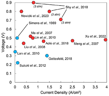
Figure 14. The performance of several DAFCs. Low-temperature DAFCs are denoted by blue markers whereas the red markers represent DAFCs that operated at high temperature.
Download figure:
Standard image High-resolution imageCurrent and future challenges
Despite the encouraging results reported thus far, several scientific and technological barriers distinct to DAFCs remain that must be addressed.
Low temperature DAFCs (AFCs and AEMFCs)
The kinetics of the AOR are notoriously sluggish [133], requiring the use of highly active electrocatalysts to overcome this hurdle. Platinum is generally considered as an excellent candidate due to its strong nitrogen adsorption strength accommodating the dehydrogenation of NH3; indeed each of the best performing AEMFCs reported in the literature have used such materials. However, this also means that these materials can be easily poisoned by strongly adsorbed reaction intermediates blocking the active sites of the catalyst. Whilst the rate of the AOR could be increased simply by operating the cell at a higher temperature, this will present durability issues for the electrolyte membrane and so there is a fundamental need to develop electrocatalysts with both high performance and improved durability. Fuel crossover is also a factor to be considered as it can lead to a large fall in cell performance. In one of their experiments, Suzuki et al [118] observed significant ammonia oxidation at the cathode which contributed to a drop in cell open-circuit voltage from about 1 V to 0.54 V.
Ammonia-Fueled solid oxide fuel cells
As they exhibit good activity for both the ammonia decomposition and H2 electro-oxidation reactions, Ni-based cermets have been used extensively as DA-SOFC anodes. Even so, the durability of such materials remain a concern. Yang et al [134] performed a stability study of a Ni/Yttria-stabilized zirconia cermet anode in a SOFC fueled by ammonia and whilst they did not observe a marked performance loss over 24 h at 600 °C or 700 °C under the open-circuit state, they did observe a considerable roughening of the anode surface due to the partial nitriding of nickel. With the deleterious effects observed to be larger at 600 °C, there is a need to develop anode materials with high catalytic activity towards the ammonia decomposition reaction at lower temperatures.
Advances in science and technology to meet challenges
Low-temperature DAFCs- development of improved electrocatalysts for the AOR
Several strategies have been investigated in an effort to improve the catalytic activity and durability of platinum-based catalysts for the AOR. Alloying Pt with other metals such as Ir, Ru, Pd, Zn and Ni to create binary and ternary catalysts has shown promising improvements in catalytic activity and/or durability depending on the alloyed metals [135–139]. Tailoring the chosen synthesis route to control nanoparticle surface area and morphology is also an important consideration. For example, cubic Pt nanoparticles have exhibited greater activity than spherical particles for the AOR due to an increased number of exposed (100) facets [140, 141].
The development of cheaper Pt-free materials is also a key area of catalyst design [142–145]. Xu et al [146] synthesized a NiCu bimetal catalyst via the electrochemical co-deposition of Ni and Cu onto carbon paper. Although it was not as electrocatalytically active as a Pt/C anode, it was not poisoned by ammonia which was a very significant result.
SOFCs
Again, alloying of the nickel-based anode with species such as SrO, Mo and Cr [123, 147, 148] has proved an effective strategy to improve the activity of the anode with respect to the ammonia decomposition reaction. Wang et al prepared a Ba-modified Ni/YSZ anode using a one-pot solid-liquid method and reported that this material allowed for complete ammonia decomposition to be realized at only 600 °C. Coating of the Ni-YSZ anode with cerium oxide nanoparticles has proved to be another effective strategy [124].
Concluding remarks
DAFCs offer a route for efficient energy conversion with a fuel considerably easier to transport and store than hydrogen. A range of DAFCs have been demonstrated to have impressive performance, sometimes comparable to that achieved using hydrogen as fuel, which could allow for these devices to find utility in a swath of applications. However, further development of DAFC is required. With regards to low-temperature DAFCs such as AFCs or AEMFCs, focus should be on the development of highly active anode electrocatalysts for the AOR. Direct ammonia SOFCs require stable anode materials that can catalyze the ammonia decomposition reaction at lower temperatures; this will help to mitigate the degradation of common anodes such as Ni/YSZ.
Acknowledgments
The authors gratefully acknowledge financial support from the University of St Andrews.
10. ICEs, boilers, furnaces, turbines
Christine Mounaïm-Rousselle1, Pierre Bréquigny1, Fabian Mauss2, Epaminondas Mastorakos3, Mara di Joannon4, Pino Sabia4, Agustin Valera-Medina5 and William I F David6,7
1Laboratoire PRISME, University of Orléans, Orléans, France
2Institute of Power Engineering, Brandenburg University of Technology, Cottbus, Germany
3University of Cambridge, Cambridge, United Kingdom
4STEMS-CNR, Naples, Italy
5Cardiff University, Cardiff, United Kingdom
6ISIS Neutron and Muon Source, STFC Rutherford Appleton Laboratory, Harwell Science and Innovation Campus, Didcot OX11 0QX, United Kingdom
7Inorganic Chemistry Laboratory, University of Oxford, South Parks Road, Oxford OX1 3QR, United Kingdom
Email: christine.rousselle@univ-orleans.fr, pierre.brequigny@univ-orleans.fr, fmauss@b-tu.de, em257@cam.ac.uk, mara.dejoannon@stems.cnr.it, pino.sabia@stems.cnr.it, ValeraMedinaA1@cardiff.ac.uk and bill.david@stfc.ac.uk
Status
To reach the 2050 European Commission carbon neutrality target, the share of carbon-free electricity for energy, transport and heating/cooling systems must increase significantly. Storing renewable electricity to secure electricity supply in high energy-density chemical vectors, is attractive for sectors that are difficult to electrify such as electricity production, process industries and transport that spans from passenger cars, buses and trucks through to maritime shipping and aviation.
Advocates of the hydrogen economy consider hydrogen as the solution to the challenge of large-scale high energy-density chemical energy storage. Ammonia has received significantly less attention apart from being considered as a 'mere' hydrogen carrier for the delivery of the hydrogen economy despite having many practical advantages over hydrogen. These include lower cost per unit of stored energy, higher volumetric energy density, easier and more widespread production, handling and distribution capacity and better commercial viability. Essentially ammonia outperforms hydrogen in almost every aspect of a future carbon-free energy economy and infrastructure. Additionally, of crucial importance both technically and financially, ammonia offers the reuse of many components of the existing fossil-fuel infrastructure including pipelines, distributed storage, LNG terminals, LPG forecourts, ICEs.
As a carbon-free chemical with an existing massive international infrastructure, ammonia can supplant the importance of hydrogen in decarbonizing power, transportation and heavy industrial processes. An ammonia-centered future energy economy does have its challenges and significant investments need to be redirected to addresses these issues. A viable retrofitted energy system and infrastructure based on green ammonia production, transportation, storage and combustion with zero carbon foot-print faces several scientific and technological challenges [42, 149].
Ammonia is by its nature carbon-free and its oxidation offers the possibility of zero-CO2 emissions. However, it has a low energy density (around 40%) compared to fossil fuels, a very low flame propagation velocity and high auto-ignition temperature. Up to date, the application of ammonia as the main fuel in any energy systems, such as ICEs, gas turbines (GTs) and industrial burners (IBs) is still in its infancy despite of numerous announcements, especially from Marine Engine Manufacturers, in the roadmap announced by the International Maritime Office [150]. The principal issue is the stability of ammonia combustion, a problem made more complex with the emission of highly polluting chemical such as nitrogen oxides (NOx and N2O) emissions and the slippage of unburned NH3. Recently, a number of pilot-scale studies have involved ammonia and an additional fuel such as NH3 addition in diesel and gasoline cars [151, 152], and NH3 co-firing in coal furnaces and methane/ammonia GTs [42].
Ammonia can only be considered to be a real carbon-free fuel if its combustion is based on pure ammonia or ammonia-hydrogen blends, the latter being produced by introducing a local ammonia cracking system. The usage of ammonia and ammonia-hydrogen blends for MILD (Moderate or intense Low Oxygen Dilution) combustion burners [153] is showing promise [154] (see table 4).
Table 4. Main technical and R&D challenges to develop ammonia combustion technology.
| Technology | Challenges | R&D focus |
|---|---|---|
| Internal combustion engine |
|
|
| Gas turbine |
|
|
| Burner and boilers |
|
|
Current and future challenges
Despite the GTs are one of main sources to generate large power outputs employing a very small footprint per unit of power generated, they remain very complex technologies. Unfortunately, the use of ammonia in these systems leads to high contents of NOx emissions and other pollutants. Further, the impact of ammonia (and hydrogen traces) obtained during the various combustion stages is still unknown, requiring further research that currently denotes embrittlement/nitration impacts on high temperature performing materials. These challenges have led various groups around the globe to develop new systems to achieve low polluting profiles whilst ensuring high efficiency and low maintenance.
Different practical methods for improving engine performance while burning ammonia (i.e. increase spark energy, increase compression ratio, engine supercharging, hydrogen or gasoline blends, etc) have been used from the 60s and are still being tested. The latest studies confirmed that a stable combustion in spark ignition engine requires a minimum value of hydrogen (no more than 2%–5%), produced on board by ammonia cracking, to reach energy output levels comparable to conventional gasoline without knock occurrence. Improvements to the injection/ignition systems (liquid/gaseous ammonia, spark plug or diesel or pilot spray ignition) are still needed to resolve the cold start and low load issues. After that, the main challenges will remain to avoid exhaust pollutant emissions. Even if the best trade-off has to be defined, efficient post-treatment systems have to be defined, studied and developed.
In the case of burners: high swirl or multiple swirl burners, staged or multi fuel combustion are explored which at the same time allow the reduction of NOx emission and a wider range of stability. A different approach to break the mold is to consider processes that go beyond the stabilization mechanisms of standard combustion, thus avoiding the main issues related to ammonia combustion and look at advanced technologies. MILD combustion, based on local dilution and pre-heating by internal gas exhaust recirculation, has been already validated to be very effective for pure NH3 oxidation both in term of stability and very low NOx emissions at stoichiometric conditions. Indeed, due to its peculiar condition at microscale, it allows to overtake issues related to low flame speed, relying on autoignition and not on flame stabilization. In addition, due to dilution, its typical low operative temperatures fall in the range where De-NOx chemistry is active, resulting in a stable and low emission process.
Advances in science and technology to meet challenges
Knowledge of the fundamentals of all aspects of ammonia combustion, from kinetics to turbulent flame propagation, is mandatory for process optimization and solution design. Over the past five years, the scientific combustion community has successfully focused on improving the performance and efficiency of ammonia-fueled combustion systems and the fundamental understanding of ammonia oxidation.
Current engineering practice in the energy and propulsion sector increasingly uses computational tools for the design of innovative systems due to the cost associated with extensive physical testing and the speed with which innovations are required to decarbonize these sectors. Hence, when a reciprocating engine, GT or furnace has to operate with a new fuel, computational fluid dynamics codes are run in order to provide information on the flame shape, location, stability, heat transfer, wall temperature and emissions such as NOx [155]. However, when a new fuel is introduced, the turbulent combustion modelling approaches as developed over decades of work require re-validation. Further theoretical developments are required to capture the combustion specifics of neat ammonia and ammonia blended with H2 and the resultant relatively weak NH3 flames that prone to extinction due to strain. Such developments are imperative if the application designers are to have reliable tools to simulate NH3 devices.
The main challenge, in both standard and MILD combustion systems that work at atmospheric pressure, is to find the most useful fluid-dynamic configuration to scale up devices for widening the operative range while minimizing emissions. The availability of reliable tools to design and optimize practical devices is essential. On this basis, the development of kinetic models, effective for both low to high temperature and pressure, is crucial. Moreover, the validation of combustion processes based on gas recirculation at higher pressure would be very relevant for extending their application also in power sector, with particular regard to micro-turbines.
As ammonia burns at low flame speeds, as highlighted in figure 15, with low extinction strain rates, all combustion technologies have a common prerequisite that reaction kinetics at limiting conditions are activated [156]. It was recently observed that under these conditions the reaction kinetics switches from N1 to N2 chemistry [157]. With increasing pressure this trend becomes stronger. N2 kinetics is found to be chain propagating which allows improved stability of combustion, while N1 chemistry is chain breaking and is quenched at already less stressed conditions. From a scientific point of view, N2 kinetics are not yet well understood and more research is required in this field. In addition, it has also been shown that NH3 has a significant role as strong collider in three-body reactions due to its molecular characteristics [158, 159]. This affects the NH3 kinetics at low-to-intermediate temperature ranges and at high pressure and unaccountably is generally disregarded in current kinetic models. Further steps are required to systematically quantify the efficiency of NH3 as a third body component in combustion reactions.
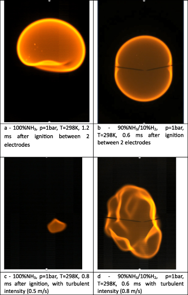
Figure 15. This figure illustrates the specificity of ammonia/air flames. Direct visualization reveals a specific orange color due to the chemiluminescence of NH2 radical. Ammonia/air flames, even at stoichiometry, is so slow than it cannot be centrally maintained by the effect of buoyancy (a). The addition of hydrogen enhances flame propagation speed and stability (b) and the interaction with turbulent vortices (c), (d). Courtesy of PRISME- Université ORLEANS -Ignition engine.
Download figure:
Standard image High-resolution imageConcluding remarks
Ammonia, as an established future fuel option, can mitigate carbon emissions entirely. The emissions challenges, however, are not fully removed as unwanted NOx and N2O can, under suboptimal conditions, be produced. These chemical not only have a significantly larger global warming potential than CO2 but are substantial contributors to poor air quality and resultant respiratory diseases.
The use of different novel combustion concepts based on (a) ammonia pre-cracking; (b) stratified injection; (c) exhaust gas recirculation; and (d) optimized power cycles and/or combustion modes can all enable efficiency improvement and low NOx combustion from Ammonia GTs, ICEs and burners.
A rapid scaling up of the systems that have already proven their effectiveness at bench scale is essential for speeding up the deployment of ammonia. Research into kinetics mechanisms and turbulent combustion modelling focused on NH3 premixed and non-premixed flames are requires as all current models used in practice and in engineering tools must be revisited and revalidated with focused experiments on NH3 flames and direct numerical simulations to extract the right turbulent-chemistry interaction trends. It is also important to evaluate the use of advanced technologies that are proven to be effective in burning NH3, in as-yet untested applications. Beyond the engine itself, research into after-treatment requires collaboration with chemical process industries to transfer existing knowledge to optimize the system of power generation and exhaust cleaning.
Acknowledgments
This work has been supported by LE STUDIUM Loire Valley Institute for Advances Studies through its LE STUDIUM Research Consortium Programme.
11. Ammonia to power applications: maritime
Sofia Fürstenberg Stott and Conor Fürstenberg Stott
Fürstenberg Maritime Advisory, Pyntvägen 3, 295 38 Bromölla, Sweden
Email: sofia@furstenbergmaritime.com and conor@furstenbergmaritime.com
Status
Development of Ammonia as a maritime fuel, though in its infancy, has recently seen remarkable acceleration. Underlying this development is the global commitment by the International Maritime Organization (IMO) in 2018 [160], to reduce absolute carbon emissions from international shipping by 50% from 2008 levels by 2050. This has driven strategic and regulatory development. Subsequently, industry has elevated those IMO ambitions through coalition initiatives such as the Call to Action for Shipping Decarbonization [161]. For most of the sea-borne transport, electrification is impossible due to battery energy density constraints which would necessitate an unfeasible network of recharging stations upon the oceans. Suitable, low-carbon chemical fuels must therefore be found.
Carbon emissions per tonne/mile carried at sea are lower than all other forms of transport. Nevertheless, as over 80% of goods movement performed by the global economy occurs at sea, shipping still represents 3% of GHG emissions. A leading study from UMAS and the COP 26 Climate Champions for the Getting to Zero Coalition [162] recommends that 5% of international shipping requires transition to zero emission fuels by 2030, to set a trajectory in line with the Paris agreement goals. That would amount to almost 16 MT conventional fuel-equivalence annually.
For maritime, several viable alternative fuels have been identified (e.g. bio-MGO, bio-LNG, e-MGO, e-ammonia, CCS + low-carbon ammonia, bio-methanol). Numerous transition pathway studies—however different in their specific outcomes, where some place more optimism on biofuel or sustainable carbon sources—all place a key role on ammonia [163–166].
As an average outcome of scenarios in these different reports, ammonia is expected to constitute 40%–60% of the total energy mix for global shipping in 2050. This however is dependent on a multitude of factors, such as e.g. the cost of electrolysis, carbon air capture costs and public safety perception. Development in SOFC technology is expected to much improve the energy efficiency of production of renewable ammonia, and a first such demonstration plant is now being built by Haldor Topsoe [167].
If such levels of ammonia use are to be reached for maritime, coordinated efforts across industry sectors will be needed. It was estimated in November 2020 by the energy transitions commission [168] that 75%–90% of the required capital outlay for an end-to-end maritime pilot would constitute the land-based fuel production.
In support of progressing ammonia maritime fuel, the industry does have considerable experience handling ammonia as a bulk cargo, with up to 17 M tonnes traded by sea annually. It is therefore envisaged that the development of ammonia from a maritime cargo to also burning it as a fuel, may follow a somewhat similar technological and operational evolution to that of LNG over the past decades. The getting to zero coalition and UMAS include this among other viable transition pathways in their transition strategy report [169].
Current and future challenges
Current development of maritime ammonia fuel is predominantly technological. Efforts center upon the engines and fuel systems, the ship design, and bunkering solutions. Of projects announced since the beginning of the pandemic, there is high participation from the OEMs, who engage in numerous, often large, industry collaborations. With ammonia engines currently rated at TRL levels 5–6 [163], key remaining challenges for bringing ammonia engines (both two-stroke and four-stroke) to market include achieving optimal combustion and mitigating emissions such as nitrous oxide and unburnt ammonia. Corrosivity to yellow metal components and the optimization of pilot fuel are other issues to be solved. First yard deliveries are expected in 2024.
Ammonia is a toxic chemical. Concentrations as low as 1 ppm can be sensed by humans, and concentrations above 300 ppm can have adverse health effects with a potentially lethal outcome. Marine and coastal organisms are similarly sensitive to any accidental discharges into the sea. Ammonia's flammability is in the range of 15–30 v/v % in air. Knowing these risks, design solutions must be developed in conjunction with development of rules and regulations to satisfactorily manage these designs. Pilot studies [170, 171] are crucial in advancing these solutions.
Public perception on ammonia safety is likely to impact the speed of development. Maritime expertise for handing bulk ammonia exists in the context of an exclusive segment where specific design and training is deployed. Bringing the substance aboard as a fuel in other segments may see seafarers refusing to set foot onto a ship powered by ammonia if safety has not been conclusively handled. Concerns must be intrinsically addressed with crew training programmes and such initiatives are already emerging, The Ammonia Safety Training Institute and Australian Maritime College University of Tasmania have recently released a call for expression of interest for development of ammonia bunker safety training course [172].
The single key driver behind the development of maritime ammonia fuel is the opportunity to reduce carbon emissions. Conventional ammonia, produced from natural gas, does not present any carbon reduction potential unless its manufacturing biproduct –CO2– is captured and sequestered, thus incurring a high additional renewable energy demand. It is essential therefore, that reliable certification and verification schemes are introduced to ensure that, as low-carbon ammonia reaches the market, GHG reductions are transparent and quantified. This includes fugitive emissions along the transport chain. This requirement is critical to motivate investment. Ensuring that any certification schemes are compatible across industry sectors and comparable with other alternative fuels, will be essential for this work.
Certification aside, the deployment of appropriate policy and regulations are above all the key catalyst to engage sufficient investment toward the scale up of any alternative maritime fuels. The FuelEUMaritime Initiative, which will soon place shipping within the catchment of the EU ETS (EU Emission Trading System) is such an initiative. On international level, July 2023 will see the 80th meeting of the IMO Maritime Environment Protection Committee (MEPC 80). This meeting is scheduled to adopt a revised GHG reduction strategy, possibly in line with a zero by 2050 target and also finalize a 'basket' of mid-term measures for development and later adoption. Attached to these deliverables is the adoption of lifecycle GHG and carbon intensity guidelines for maritime fuels, as well as progressing sustainability criteria for the same. These guidelines deal with the lifecycle of maritime fuels split into two parts, namely from production to the ship (WtT—Well to Tank) and the consumption by the ship (TtW—Tank to Wake). The IMO members will decide whether to encompass the entire lifecycle of the fuel from (WtW—Well to wake) or leave the WtT element to be dealt with in national GHG inventories.
From the perspective of ammonia, there is seemingly an advantage in the TtW model because ammonia does not result in direct carbon emissions. However, such a scenario also risks encouraging the use of grey ammonia, thereby potentially both increasing global GHG emissions and disincentivising scale up of low carbon ammonia production. Not taking a full lifecycle perspective may also disincentivise other fuels like biofuels. IMO therefore needs to resolve a great deal of complexity in order to ensure that any measures adopted do truly result in the emissions reduction. In doing so, it similarly has the opportunity to lead other industry in terms both of competency and speed of transition.
Advances in science and technology to meet challenges
Low-carbon and renewable ammonia infrastructure must scale quickly to advance maritime decarbonization. If the industry is to reduce GHG emissions in alignment with Paris Agreement goals, it must decarbonize far faster than the current IMO trajectory: To go from ∼180 Mt to ∼600 Mt+ by 2040, ammonia production needs to grow around 10% per year, while all new ammonia manufacturing as well as the existing production must be decarbonized. For this to be possible, a fast ramp-up will be necessary, while taking care of sustainability demands.
Science and Technology advances in multi-sectoral supply and demand analytics could help stakeholders share risk and opportunity and thereby remove key ramp-up barriers. The maritime industry will, therefore, not be able to develop a renewable fuel infrastructure, be it ammonia, methanol, biofuel or other low-carbon solutions, on their own. Cross-sectoral coordination with, for example, aviation, the food industry and agriculture, will be necessary to plan supply, levelling risk and utilize synergies within the emerging energy shift.
A further urgent initiative is the acceleration of the development of so-called green corridors figure 16. The Clydebank Declaration [173] commits to minimum of six green corridors within this decade. The Global Maritime Forum recently released a discussion paper [174] on definitions and approaches for green corridors, which ammonia stakeholders now need to explore how to get involved. To help such a process, a blueprint framework for green corridor development has been suggested by the Maersk McKinney Møller Centre for Zero Carbon Shipping [175].

Figure 16. Examples of emerging green corridors, and signatories to the Clydebank Declaration: Australia, Belgium, Canada, Chile, Costa Rica, Denmark, Fiji, Finland, France, Germany, Ireland, Italy, Japan, Republic of the Marshall Islands, Morocco, Netherlands, New Zealand, Norway, Palau, Singapore, Spain, Sweden, The United Kingdom of Great Britain and Northern Ireland, The United States of America.
Download figure:
Standard image High-resolution imageAs mentioned above, certification of ammonia's carbon profile is essential. This will be required 'well-to-wake', within common boundary conditions for all types of fuel. A trusted method for traceability of specification and origin, however complex, must underpin this. Emerging digital concepts involving tagging and blockchain deployment, could possibly leapfrog such complexity. Digital technologies should be invited at an early design stage to develop minimum common standards which could eventually lead to fuel-agnostic certification schemes.
Safe designs of ammonia-fueled ships and fuel systems, ammonia bunkering solutions, personal protective equipment and accident mitigation systems need to be developed, trailed, and deployed. How to do this at scale, with high speed, low cost and with highest safety standards, will require strong collaborative action.
Concluding remarks
Industry analysts and think tanks may not exactly agree what specific pathways will most effectively decarbonize maritime transport. They do however agree that low-carbon and renewable ammonia looks to play an essential role. A widespread industry consensus further highlights the need for a fast ramp-up of (net-) zero carbon ammonia production, and supply-and demand sector-coupling to allow for the sharing of risk and opportunity with adjacent sectors.
High attention to public perception on ammonia safety, and the successful launch of first pilots will be critical enablers for scaling of maritime ammonia. Another key enabling factor will be the industry-wide implementation of a well-to-wake GHG standard and certification scheme, ensuring actual decarbonization progress and an equitable transition.
Collaborative efforts to bridge risks and to find mutual value, not least through engaging in green corridors development, are actionable pathways for actors across a wide ammonia stakeholder environment.
Acknowledgments
Thank you to Tristan Smith, Associate Professor at UCL Energy Institute and Director at UMAS, and to Tue Johannessen, Vice President, Business Development Fuel Cells & Energy Storage, Alfa Laval, for your invaluable insights and comments.
12. Ammonia to power applications: aviation
James Barth and Mark A Picciani
Sunborne Systems Ltd, c/o STFC Innovations Ltd, R71 Rutherford Appleton Lab, Harwell Campus, Didcot OX11 0QX, United Kingdom
Email: james.barth@sunbornesystems.com
Status
The idea of ammonia as a fuel for aviation gas-turbine engines was first examined in the 1960s. Whilst it was found to be possible to convert an existing GT to burn ammonia, it typically required the addition of hydrogen to an equivalent of 28% dissociation of ammonia to have equivalent ignition energy, quenching distance, and flame-stability properties to methane [176]. Given the mass and compactness challenges of incorporating ammonia cracking into an engine architecture, it has otherwise been ignored in favor of other alternative fuels. Even relatively recent 'Ammonia to Power' reviews (e.g [40]) have not re-examined its potential for aviation propulsion.
This is beginning to change, however. In 2020, Reaction Engines (RE) announced the completion of a joint study with partners at the Science and Technology Facilities Council (STFC) that showed an ammonia-fueled aircraft was a viable proposition [177]. In such a system, the modified fuel system would harvest exhaust heat to drive ammonia cracking in a reactor based on RE's heat exchanger technology and STFC-developed catalysts. Such a reactor would be compact and light enough for service in a civil airliner without a significant penalty.
The emerging importance of ammonia as an aviation fuel is leading others to re-examine ammonia-based architectures including electric-hybrid systems [178, 179] and electrification with solid oxide fuel cells [180]. Additionally, NASA has awarded two University Leadership Initiative awards in 2021 and 2023. In 2021 the total award was $10 million and was awarded to the University of Central Florida [181] and more recently, the total award was increased to $25.1 million and was awarded to Tennessee Technological University [182].
This renewal of interest appears to be driven by a key feature of ammonia: it only requires modest cooling (below 240 K) to liquefy at standard conditions, and when sub-cooled to 211 K or below, it remains a liquid at pressures as low as 0.1–0.2 bar [183]. As such, it is likely the only zero-carbon fuel that can be stored in aircraft wing tanks, decarbonizing flight without radical changes to aircraft architecture. Such an aircraft could feasibly address most short-haul aviation flights, allowing for rapid decarbonization of a large part of the civil aviation market [177].
Current and future challenges
Whilst it is proven that GT-based engines can run on ammonia [176], there are still three challenges to be addressed before ammonia can move into commercial aviation service. The first of these challenges is to address the combustion of ammonia (NH3/H2/N2) fuel blends sufficient for use in aviation GTs. The second major challenge is to design and integrate the many components of an ammonia fuel system. The third challenge area is to define safe operating envelopes and procedures for the technical systems previously mentioned, ultimately allowing for flight test and certification of an ammonia-fueled aircraft.
The first and most apparent challenge with the combustion of ammonia is the control of NOx emissions due to the fuel-bound nitrogen. Due to this, the increased potential for elevated NOx emissions is further compounded by the necessity to introduce a larger quantity of fuel (for a similar fuel power requirement) due to the reduction in LHV of ammonia.
The second challenge arises due to the lower reactivity of ammonia compared to kerosene. This is mainly manifested through a narrowing of flammability limits and reduced laminar flame speeds. The implications of this are that conventional injector technology may not provide sufficient stabilization mechanisms across the duty cycle and alternatives/modifications must be sought. On the system level, the reduced reactivity may necessitate an increase in combustor volume.
The fuel system challenge lies in the design and integration of the many elements required. Ammonia tanks must be conformable to fit in aircraft wings, be able to maintain storage temperatures, and safely manage ullage volume in flight. Commercially available ammonia pumps are not fit for purpose, and will need redesign. A means to provide in-situ pilot fuel (e.g. hydrogen) to promote ammonia combustion must also be developed.
Whilst its fire hazard is much lower than kerosene, ammonia is known to be toxic to humans and the wider environment. Design and operational safety factors will need to be addressed at system and subsystem levels before they can be integrated into any aircraft. Additionally, all major safety concerns associated with ammonia release in potential aircraft failures will have to be addressed. Ultimately, any practical application of ammonia in aviation must be certified for flight by aviation authorities worldwide.
Advances in science and technology to meet challenges
To develop an ammonia fuel system for aviation, concerted effort will be needed to design a tank system that incorporates within wing structures whilst including sufficient insulation or other thermal management systems. Ullage may be managed either by promoting a vapor/liquid equilibrium similar to that in ammonia bottles, or else the use of an inert gas system to relieve drops in pressure. Pumping solutions must be made flight-weight whilst meeting the unique flow and pressure demands of an aircraft fuel system.
Fuel and engine systems must also use ammonia-compatible materials and be designed to prevent on-board leakage of ammonia fuel. Otherwise, the principal safety challenges for ammonia in aviation are related to large releases during a 'survivable crash' (i.e. runway excursion) or the breakup of an aircraft over a populated area [184]. Studies, such as [185], are in planning to understand these hazards and make recommendations on how to mitigate these dangers and allow for certification.
To counteract some of the challenges arising from the low the reactivity of pure ammonia as a fuel in combustion systems, two options are commonly explored: the use of a higher reactivity pilot fuel and altering of the properties of the fuel steam by doping or cracking. Provision of pilot fuel, although effective, is unlikely to be a long-term solution due to the necessity of a secondary fuel system and its associated mass and complexity increases. Similar conclusion may be drawn for doping. Cracking can be shown to improve flammability limits [186] and flame speeds, but it does not alter the LHV as significantly as doping or a pilot fuel so the demand on the single fuel system remains as for a pure ammonia albeit with slightly higher volumetric flow rates. On-board cracking of ammonia driven by engine waste heat may be viable, provided mass and compactness requirements can be met. One reactor system capable of meeting these requirements is in development at present time [187], whilst others are being studied as part of system level studies [178, 181].
NOx emission mitigation has been shown to be sensitive to the injector architecture and injection strategy [188, 189] with the rich burn, quick-mix, lean burn (RQL) strategy providing the largest benefit in terms reducing emissions. Selective catalytic reduction has recent been investigated [190] showing that a 95% reduction in NOx can be achieved for a 0.5% increase in fuel consumption.
Concluding remarks
Advances in cracking and combustion technology are progressing to a point where ammonia is able to serve as an effective zero-carbon replacement for jet fuel. There remain challenges in understanding the best means to burn ammonia in a jet engine, how best to design an entire ammonia-based fuel system and prove the safety case to the satisfaction of certifying authorities. None of these challenges appear insurmountable, and with concerted effort, it is entirely possible to see ammonia-based aircraft ready for take-off before 2040.
13. The immediate future: funded and proposed projects
Kevin H R Rouwenhorst1 and Proton Ventures2
1Ammonia Energy Association, 77 Sands Street, 6th Floor, Brooklyn, NY 11201, United States of America
2Karel Doormanweg 5, 3115 JD Schiedam, The Netherlands
Email: krouwenhorst@ammoniaenergy.org
Status
The ammonia energy economy is beginning to take off and there is an urgent need to develop and demonstrate ammonia-based projects along the full value chain. An overview of current and future methods for ammonia production and utilization is presented in this section and illustrated in figure 17. This section will highlight a small sample of the current research projects and commercial demonstrations of low carbon ammonia production and utilization for energy applications.

Figure 17. Schematic of the ammonia economy. Reproduced with permission from [17]. © IRENA 2022.
Download figure:
Standard image High-resolution imageRenewable ammonia production has historically been produced from steady hydropower combined with alkaline electrolysis for hydrogen production [22]. More recently, renewable ammonia production from fluctuating solar PV and wind energy has been proposed. Due to the fluctuations in renewable electricity, the flexibility of ammonia production to follow this intermittency must be improved and storage buffers will also be required to address fluctuations in power, especially for small-scale operations.
The partial decarbonization of an existing natural-gas based ammonia plant in Puertollano, Spain, is an example of the decarbonization of an existing ammonia plant. The project consists of solar PV, batteries, PEM electrolyzers, compressed hydrogen storage, and compressed oxygen storage [191]. This 150 M€ project was commissioned in 2022 and decarbonizes about 3% of the current ammonia production capacity (200 kt-NH3/y). Extensive hydrogen storage with a capacity for more than a week has been installed to ensure continuous delivery of hydrogen to the ammonia plant.
To reduce the cost of extensive hydrogen storage, more flexible Haber–Bosch ammonia synthesis loops have been researched. In 2014, the University of Minnesota started operating a 25 t-NH3/y wind to ammonia demonstrator, proving that a Haber–Bosch plant can operate with an intermittent wind load profile [192]. Similar demonstrators were also built in Japan and the United Kingdom [17].
Large-scale, renewable ammonia plants based on solar and/or wind energy have been announced with the aim to scale-up to gigawatts (1 Mt-NH3/y) around 2025 or 2026. However, the performance of renewable ammonia production from fluctuating renewables remains a challenge at a global scale.
Ammonia can be utilized as a fuel for power in many applications, a range of which are discussed in sections 11–13. Early demonstrations for ammonia as a fuel for co-combustion has been demonstrated in a coal-fired power plant, where just below 1% of the coal was replaced with ammonia [193]. Furthermore, ammonia combustion in engines, turbines and fuel cells is an increasingly active field of research [40]. Commercialization, for example, of maritime engines and GTs is expected around 2025 [17].
Ammonia can be utilized as a source of hydrogen carrier. Ammonia crackers can be utilized to convert ammonia to hydrogen and nitrogen gas. These ammonia crackers find applications in the metallurgy industry for nitriding at small scale, e.g. 20–600 t-NH3 y−1 cracked [194]. Ammonia crackers with a capacity of up to 1400 t-NH3 d−1 cracked are operated commercially for heavy water production [195]. Both applications do not require purification of the hydrogen.
Current and future challenges
The key challenge for renewable ammonia production is coupling fluctuating renewable electricity input with renewable ammonia production capacities. In 2023, this is the principal barrier for final investment decision in many renewable ammonia projects.
Ammonia faces four principal challenges before it can be considered to be an established energy carrier on a global scale. Firstly, the introduction of a toxic chemical like ammonia as a fuel requires careful considerations and the adequate precautions. Secondly, ammonia is does not burn as easily as hydrogen or hydrocarbon fuels or [40], implying modifications are required for ammonia burners. Thirdly, many ammonia power applications are under development, and firm policy can only be made when these technologies are commercially available. Lastly, emissions from ammonia combustion must be addressed to prevent ammonia slip and nitrogen oxide emissions.
Advances in science and technology to meet challenges: ammonia production
Commercial pilot plants for intermittent renewable ammonia production are currently under construction. Importantly, these plants are all pre-commercial and involve testing various strategies that include flexible ammonia synthesis, as well as battery and hydrogen storage technologies.
For example, a 1.5 kt-NH3 y−1 (4 t-NH3 d−1) pilot plant that was recently announced in Jorf Lasfar, Morocco, to be built at the Mohammed VI Polytechnic University facilities. This multiple-MW scale pilot plant consists of alkaline electrolysis and PEM electrolysis, nitrogen purification, compressed hydrogen storage and an ammonia synthesis loop. An electricity emulator allows for simulating renewable electricity profiles from anywhere around the world.
Alongside the near-market approach at Jorf Lasfar [196], the University of Minnesota in the Unites States [197] and EU consortia, such as FlexNConfu [198] and ARENHA [199], are exploring non-conventional ammonia synthesis technologies such as low-pressure (20 bar) sorbent-enhanced Haber–Bosch [200]. These approaches provide the opportunity to de-risk future commercial projects.
More speculatively, direct ammonia production from water and air via electrochemical processes is being studied by numerous research groups [71]. However, this remains a long-term scientific challenge and is discussed further in section 7.
Advances in science and technology to meet challenges: ammonia for power
The understanding of ammonia combustion for heat and turbines has advanced over the past few years [201, 202]. The burner configurations and fuel mixtures have been studied under laboratory conditions. The current focus is on scale-up to commercial operating conditions.
Novel ammonia conversion technologies, such as SOFC, have been validated [40, 202]. An ammonia-fueled 2 MW SOFC will be demonstrated in a ship in the near future [17]. Alternatively, cracked ammonia can be fed to an AFC for back-up power generation.
Various ammonia synthesis licensors have focused on ammonia cracking over the past few years, resulting in commercial ammonia cracking solutions being available today. These designs rely on tubular reformers also used for natural gas conversion to hydrogen. Novel ammonia cracker concepts are also under development [203], to be commercialized at a later stage.
Ammonia energy solutions must be designed such that combustion emissions such as NOx , N2O, and ammonia slip are minimized below currently acceptance thresholds. Solutions for reducing ammonia combustion emissions have been commercialized decades ago, but not developed for the future ammonia applications. For example, deNOx catalysts are today utilized to clean up NOx and N2O emissions in the exhaust of GTs and vehicles, using ammonia as a reducing agent for NOx and N2O conversion, and residual ammonia after deNOx can be converted to nitrogen and water using an AMOX catalyst.
Concluding remarks
A growing number of ammonia energy projects are under development along the value chain and across all the technological readiness levels up to commercial pilot demonstration. Together, these provide a pathway for commercialization around the mid-2020s.
Acknowledgments
The author acknowledges discussions with colleagues at the Ammonia Energy Association, and Proton Ventures.
14. Understanding public acceptability of ammonia energy technologies
Andrea Guati-Rojo
Ammonia Energy Association, 77 Sands Street, 6th Floor, Brooklyn, NY 11201, United States of America
Email: aguatirojo@ammoniaenergy.org
Status
With the current applications of ammonia as a fertilizer and a feedstock for the chemical industry, existing knowledge and infrastructure, along with the attractive characteristics as a zero-carbon fuel, recognition for the use of as an energy vector and storage method is increasing. However, the successful adoption of a new technology such as ammonia energy is not only dependent on its physical/technical properties but also on societal factors, including public acceptability [204]. Little is known about public attitudes and concerns around this technology; these factors could support or delay its successful implementation.
Understanding public acceptability of a technology is complex and dependent on many psychological, social and contextual factors. It is true that developing a new technology often brings several benefits for the public, especially when referring to zero-carbon technologies; yet, as with any project involving the public, it is always a challenge to understand the general public's process of acceptance. Numerous factors start playing an important role, such as associations, place attachment, cultural backgrounds, values, beliefs and many more [205] (see figure 18).
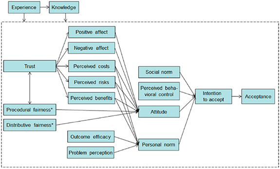
Figure 18. A schematic representation of the technology acceptance framework. Reprinted from [206], Copyright 2012, with permission from Elsevier.
Download figure:
Standard image High-resolution imageExperts have been trying to analyze these complex interactions between the general/local public and the development of new energy technologies [207]. Several cases illustrating what elements play an important role in the development of low-carbon energy technologies have been explored by researchers in the field of environmental psychology. An interesting example is the case of wind turbines in the UK. Despite several positive outcomes for the environment and other benefits compared to other alternative energy options, there is a relatively high level of public opposition to wind farms in the UK at a local level. British residents understand and support renewable energy from wind at a national level, however they have additional concerns when it comes to considering developments in their own areas such as aesthetics or how it fits into the landscape [208]. Researchers point out that even though the factor of spatial proximity to the development was important when predicting resistance, attitudes were determined by more than just proximity. Factors ranging from self-interest to lack of knowledge were observed.
The example of UK wind turbines illustrates that the public acceptance of low-carbon technologies is an important element to consider and there is also increasing recognition that public perspectives need to be understood early in the technology development cycle to adequately anticipate and respond to public concerns. Doing so is considered part of responsible science and innovation [209, 210].
Current and future challenges
Ammonia energy technologies are emerging, and the public is unlikely to have much familiarity with them, unlike other low-carbon energy technologies such as solar, wind or nuclear power. This could bring additional challenges when analyzing social aspects of the technology, for example, framing [211], technological optimism [212], or preference construction [213]. Studies on emerging technologies have shown that when the general public is faced with an unfamiliar topic, they will arrive at a response drawing upon a range of their existing beliefs and thoughts about the topic and not necessarily based on knowledge.
Currently there are few public engagement studies on green ammonia as a first attempt at understanding what benefits, risk and concerns people perceive about the technology and how this might differ to experts in the technical aspects of green ammonia. Guati-Rojo et al [214] carried a public perception study in the UK and Mexico where results suggest that most of the participants in the two countries support the development of these technologies, with men being more likely to show support than women. Participants in Mexico and the UK had both negative and neutral associations of ammonia as a chemical. However overall perceptions of green ammonia were surprisingly positive. A multiple regression was performed including all variables (sociodemographic and theoretical). The model significantly predicted support for green ammonia technologies for both countries, Mexico, F(9,466) = 26.720, p = < .001 and UK, F(9,267) = 28.445, p = < .001. When considering all variables only gender, political orientation (only for Mexico), and perception of risk and benefits as well as affect have a significant relationship with support for green ammonia technologies, as displayed in table 5.
Table 5. Linear regression analysis of support for green ammonia technologies (sociodemographic + theoretical variables) Guati-Rojo et al. Reproduced from [214]. CC BY 4.0.
| Mexico | UK | ||||||
|---|---|---|---|---|---|---|---|
| Independent variables | B | SE | p | B | SE | p | |
| Socio-demographic variables | Gender | −0.153 | 0.067 | * | −0.293 | 0.077 | *** |
| Age | −0.028 | 0.033 | n.s. | −0.005 | 0.032 | n.s. | |
| Working Status (Unemployed) | |||||||
| Employed | −0.032 | 0.148 | n.s | −0.096 | 0.159 | n.s. | |
| Student | −0.042 | 0.177 | n.s. | 0.061 | 0.182 | n.s. | |
| Political Orientation | 0.044 | 0.015 | ** | 0.003 | 0.017 | n.s. | |
| Theoretical variables | CC worry | 0.044 | 0.053 | n.s. | 0.027 | 0.053 | n.s. |
| CC threat (you and your family, your country, developing country and developed countries) | 0.039 | 0.063 | n.s. | 0.103 | 0.067 | n.s. | |
| Risk and benefits of ammonia systems | 0.487 | 0.047 | *** | 0.234 | 0.051 | *** | |
| Affect towards green ammonia | 0.205 | 0.034 | *** | 0.427 | 0.036 | *** | |

| 0.340 | 0.489 | |||||
Adj.
| 0.328 | 0.472 | |||||
Unstandardized regression coefficients (B) and standard errors (SE). n.s. (non-significant). p< .05*, p < .01**, p < .001***. a Gender coded as: 0 (Male), 1 (Female).
Even though, there are limited studies on the topic of ammonia as an energy vector, hydrogen, on the other hand, has several public perception studies, useful to consider for ammonia. According to Gordon et al [215] even though public support for hydrogen technologies seems to be somewhat positive, it encounters limited awareness and moderate concerns about safety, challenges also observed for ammonia technologies. General conclusions from these papers also suggest that men are typically more supportive than women and that acceptance for hydrogen appears to be positively correlated with environmental awareness and trust in technology. A current study from the UK Energy Research Centre analyzing public perception of hydrogen produced using electrolysis from renewables [216] found out that cost and safety were the main concerns of participants in the focus groups.
Advances in science and technology to meet challenges
Overcoming attitudinal and behavioral barriers is critical to the ammonia energy transition. Although ammonia is not used in energy applications today, it is increasingly likely that ammonia will play a key role in the decarbonization of energy systems. This should be perceived as an advantage by developing general public studies at early stages of the technology before full deployment to minimize public opposition.
Context is fundamental to understand public perceptions of risks and benefits for low-carbon ammonia technologies. The country where the technology is developed will play an essential role on how people perceive the technology. It is recommended that technological applications are developed in a way that is sensitive to issues relevant in the particular host country.
Regulation is key; how the technology will be regulated by stakeholders will be essential for its development as trust is an important factor not only for the general public but also for experts. Ways of improving trust should be explored by policy makers, industry and academia involved in developing green ammonia.
In terms of communication, ammonia as a carbon-free fuel is an emerging technology. This should be acknowledged first when communicating the benefits of the technology. How ammonia energy is presented and who is delivering it, will play an important role for its acceptance. Studies suggest that highlighting its role in addressing CC was positively received by the general public [214] and therefore this kind of framing is likely to lead to support of the technology [211].
As research in this area continues growing more knowledge and insights will be available. Further research could consider involving additional groups comparing responses from people familiarized with the uses of ammonia as a chemical and their perception if the chemical is used as an energy vector (e.g people in contact with ammonia as a fertilizer). Explore different framings (e.g with and without CC framing), comparing ammonia to hydrogen or other alternative storage options, analyzing the impact of additional social and cultural factors (e.g beliefs and independent regulators).
Concluding remarks
It is a reality that the interest and investment in ammonia as a carbon-free fuel is increasing worldwide. Even though several barriers have to be overcome in the next coming years from a technical perspective, acceptance from the public will also be a key aspect for full implementation.
In this section, we highlight the importance of involving the public at early stages of the development of the technology. It is of fundamental importance to understand people's perceptions at any stage of a technological process considering the impact that their opinion will have during deployment. With an upstream technology, such as ammonia for energy, where its effectiveness, cost and risks are uncertain, public perception studies will point out ethical and value issues people consider important.
Trust appears to be a particularly critical factor—a lack of trust in stakeholders to develop and regulate the technology may increase the public's perception of risks and therefore decrease recognition of the benefits, even to a point where the purpose of technology is no longer acknowledged [217]. The next step of innovation is not only to consider technical aspects but to recognize the importance of a joint effort between key players to formulate an ethics of care for the future, where a comprehensive vision is in line with ethical reasoning, taking into account both public and stakeholders. This vision should be developed and be taken into account for risk communication in the field of ammonia as a carbon-free fuel.
15. The future global ammonia infrastructure: addressing food production, clean air and climate change
William I F David1,2
1ISIS Neutron and Muon Source, STFC Rutherford Appleton Laboratory, Harwell Science and Innovation Campus, Didcot OX11 0QX, United Kingdom
2Inorganic Chemistry Laboratory, University of Oxford, South Parks Road, Oxford OX1 3QR, United Kingdom
Email: bill.david@stfc.ac.uk
Status: the scale of the challenge
The challenge of displacing fossil fuels from their dominant role in the global energy infrastructure is arguably the greatest technological and political issue that humankind faces over the next quarter century and beyond. Figure 1, section 1 articulates the size of the challenge and shows that scaling up the production of fossil-free energy is challenging but feasible. It is the implementation of globally sufficient, fit-for-purpose fossil-free energy storage that is the significantly most difficult challenge to achieve in the movement away from fossil fuels.
In 2022, coal, oil and gas delivered a dominant 81.8% of global primary energy with the other 17.2% being provided by nuclear reactors and renewable energy sources; these are principally wind, solar and hydroelectricity. There is a positive message in these statistics; transitioning to 100% renewable and nuclear energy necessitates only a five-fold increase in the implementation of these technologies. While this may be within reach, the 2050 energy infrastructure is likely to be 2–3 times larger.
The most difficult net-zero challenge is to develop future carbon-free global energy storage to a scale that is commensurate with today's fossil-fuel energy storage. Even with the hypothetical access to all 225 Mt of global ammonia yearly production alongside existing pumped hydroelectric storage and potential battery storage current carbon-free energy storage only accounts for 4.1% of the potential 2022 capability to store non-fossil-based energy.
Short and long term fossil-fuel-free energy storage
Future carbon-free global energy storage will be created from a combination of wind, solar, hydroelectricity and nuclear energy sources and will be differentiated by whether the storage is short-term (intraday) or long-term (days to years). The general consensus is that intra-day storage will be electrochemical and gravitational, principally with batteries and pumped hydroelectric (PHES) because of their high efficiencies. Long-term energy storage will be chemical, where the historical and current technological evidence is that the majority of the global infrastructure is most likely to be based around ammonia and not hydrogen.
The 2022 primary energy consumption of 167.9 × 10³ TWh yr−1 corresponds to a daily global energy consumption of ∼460 TWh. With a 2023 cumulative global battery capacity of ∼2 TWh and a predicted annual increase of ∼30% future growth [218], the aggregated 2030 battery capacity may reach ∼20 TWh. The majority of this capacity will be directed towards BEVs. If this growth continues, BEVs have the potential to contribute significantly and flexibly to future global intra-day energy storage. The combination of significant battery development coupled with an evolving global ammonia infrastructure is discussed later in this section. Integrating these technologies may provide global energy storage solutions from intra-day to interseasonal that depend little on fossil fuels.
The evolving global ammonia infrastructure
Proposed in 2014, the Australian Renewable Energy Hub (AREH) (figure 19(a)), situated by the coast in the Pilbara region of Western Australia, is one of the earliest projects to address the challenges of providing renewable green energy from wind and solar on a multi-GW scale [219]. The project land area is an immense 6500 km2, larger than Delaware (US) and almost the same size of Devon (UK).

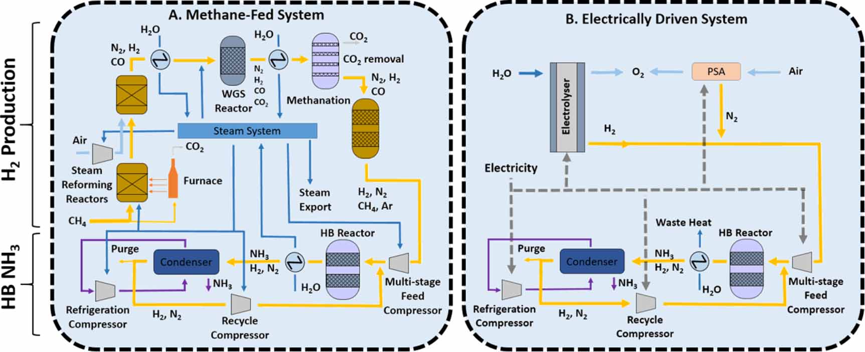
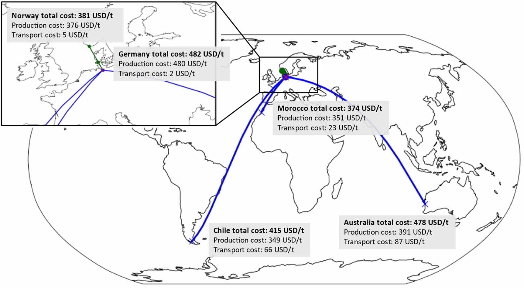
Figure 19. (a) The proposed AREH renewable energy production facility in the Pilbara, West Australia [219] (b) Global map of proposed future green ammonia projects that highlights the large number of initiatives in Australia and the Middle East. (data courtesy of the Ammonia Energy Association) The large regional circles indicate the cumulative sum of green ammonia production in millions of tonnes (Mt) and, in brackets, the total number of proposed facilities. The light green circles are centered on the locations of proposed facilities that exceed 1Mt year‒1 production. The circle areas scale with yearly ammonia production (Mt).
Download figure:
Standard image High-resolution image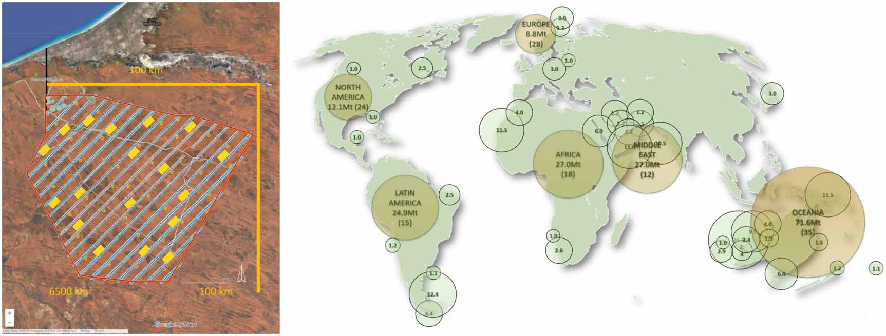
Though currently facing environmental challenges, the ten-year construction project has the aim of producing up to 100 TWh yr−1 green energy with 26 GW of green power. 23 GW are set aside for the production of ammonia from air and desalinated water, via water electrolysis and the Haber–Bosch process. The remaining 3 GW are for local use where there are opportunities, given the substantial local reserves of iron ore, not only to smelt ore but also to produce profitable high quality steel.
These local opportunities echo back to the earliest days of the Industrial Revolution in the UK where manufacturing developed and industrial cities grew around the coal fields of Yorkshire, Nottinghamshire and the lowlands of Scotland. The Green Industrial Revolution will be global; economics dictate that the most viable industrial locations for manufacture will be the co-location of raw material reserves and massive renewable energy production projects such as AREH.
Despite the Pilbara being one of the sunniest places on the planet, the AREH project involves both wind and solar, with wind accounting for over 70% of energy production. This is in large part because green ammonia manufacturing, and particularly the Haber Bosch process, requires a constant availability of power that is patently unavailable from solar farms at night. This comes with a substantial compromise to land area. The renewable energy density for AREH is ∼65 km2 (TWh yr−1)−1.
In contrast, the 37.2 km2 Benban Solar Park [220] near Aswan, Egypt, has a nominal power of 1.65 GW and an annual production of ∼3.8 TWh corresponding to a renewable energy area density of ∼10 km2 (TWh yr−1)−1. Using these two projects as exemplars, the footprint of the solar-only farm is a factor of ∼6.5 smaller than an equivalent wind and solar farm. However, this area advantage can only be achieved if technology is developed to perform at low loads and shorter start-up times for all aspects of green ammonia production, from electrolysis to the Haber–Bosch process (see section 5).
Electrolyzers are the key technology for the splitting of water; the three principal electrolyzer types are proton exchange membrane (PEM), alkaline (AEC) and solid oxide electrolyzers (SOEC) (see section 4). There have been rapid developments in the manufacturing of electrolyzers; the 2020 global electrolyzer market stood at a cumulative 26.88 MW and is predicted to increase 300-fold to 8.52 GW in 2026 [221]. With a global average primary power of ∼20 TW and, recognizing the importance of electrolysis in the decarbonization of the chemical industry, 2050 global electrolyzer capacity will be required to be around 2–8 TW, a factor of 300–1000 times more than the current predictions for 2026. This is a massive challenge. This may, in part, be addressed by the development of water thermolysis technologies using nuclear power.
Figure 19(b) shows the proposed green ammonia production gigafacilities. There are currently more than 140 proposed projects that together could provide a yearly production of ∼154 Mt green ammonia, which is similar in magnitude to the current production of fossil-fuel based ammonia. Alongside these proposals, there are international agreements moving forward for the shipping of green ammonia from Australia and Saudi Arabia to the Far East and from North West and Southern Africa, Brazil and the Middle East to Europe. Old established trading routes for fossil-fuel based ammonia will be reused for the transportation of carbon-free ammonia. Regulations are progressing within the maritime industry in no small part because of their familiarity with ammonia.
Many press articles discussing future carbon-free energy vectors have conflated ammonia with hydrogen suggesting that hydrogen is the principal player in transportation and storage. The majority of hydrogen is currently used for oil refining and the production of ammonia. In both industries, hydrogen has a fleeting existence of a few minutes and moves a few hundred meters (figure 4, section 2). There is little sign that this will change. In AREH (figure 19(a)) and the other 140 proposed renewable energy gigaprojects (figure 19(b)), it is ammonia that will be stored on-site and exported across the world.
In section 7, Salmon and Banares discuss an integrated perspective of the economic and logistical aspects of ammonia as a fuel. For wind and solar, lowest cost production will be in the sunniest and windiest places. Abundant hydroelectricity also will lead to low-cost green ammonia. They considered costings based on the delivery of ammonia to Germany where, under their scenario conditions, the local cost of ammonia is $482/t consisting of $480/t (production) and $2/t (transport). Chile and Morocco have similar production costs to one another, ∼$350/t, but the respective transport costs of $66/t and $23/t make Morocco the preferred source. Interestingly, the cost of ammonia produced by hydroelectricity in Norway is almost as competitive with its production and transport costs of $376/t and $5/t leading to a total cost of $391/t.
The shipping of green ammonia from NEOM, Saudi Arabia to the UK, the Netherlands and Germany is another proposal with significant promise [222]. Within Germany, RWE and global logistics firm VTG will jointly develop a rail distribution network for imported ammonia [223]. This network can, in principle, link up with the network of existing LPG forecourts retrofitted to supply ammonia (section 2).
The discussion in the previous paragraphs reduces down to where is the cheapest source of ammonia; the efficiency of its production is of secondary importance to the importing customer. The key fiscal criteria are the efficiencies of the various options for producing power from ammonia and the cost and scale of the attendant infrastructure. Fuel cells (section 9) and ICEs and related combustion engines (section 10) are the two main technologies that are under consideration.
In terms of energy-to-power efficiency, direct ammonia solid oxide fuel cells (DA-SOFCs) are the most efficient approach but are not at the scale to make a substantial impact now but may be the technology of choice in future decades. AFCs, which are ammonia tolerant, are less efficient than SOFCs and require significant cracking to ammonia. Again, they are not yet at a significant scale. PEM fuel cells, with a lower efficiency than both AFCs and SOFCs, require additional technology and energy to make 99.9999% pure hydrogen.
ICEs powered by ammonia are currently under significant attention and interest (section 10) with promising developments in the most efficient ways to produce the ideal ∼70–30 (by mass) ammonia |cracked-ammonia blend (section 12). Significant developments in ICE design have resulted in efficiencies approaching 50% that are similar to PEM fuel cells. As a modified engine with integrated partial cracking and, importantly, with its existing massive infrastructure, ICEs represent a strong opportunity for ammonia-powered technologies.
Zero emissions means zero carbon (CO2) and zero nitrogen (NOx +N2O) emissions
BEVs are not green. The electricity used to power BEVs is not yet 100% renewable and their manufacture has a large carbon footprint and substantial environmental impacts. The important advantage for BEVs is that they have zero gas emissions as they release neither CO2 nor NOx and N2O. However, they still contribute to particulates at a similar scale to ICE-based vehicles.
Net-zero carbon mitigates CC and is a decades-long challenge that will impact all our lives. Tackling nitrogen emissions, however, is an immediate imperative because of its impact, particularly in urban environments, on poor health, respiratory diseases and related morbidity. The ICE has experienced collateral damage as a result and its demise has been supported by many governments.
An ammonia-fueled ICE or turbine, de facto, does not produce CO2. There are, however, two significant emissions challenges, namely the elimination of NOx and N2O emissions and the removal of NH3 slippage, that must be addressed and resolved before ammonia can be considered to be a clean-air option for existing combustion technologies. While current emissions standards are measured in parts per million, clean-air environments are measured in parts per billion. Future ammonia-based energy technologies, whether combustion or fuel-cell based, must not exceed these ppb levels if they are to be considered to be clean-air options.
Globally in 2023, there are around two billion ICEs, a number that dwarfs the global numbers of electric cars (∼26 million) and hydrogen fuel-cell vehicles (<100 000), two technologies that are predominantly located in high-income countries. In order to achieve transport solutions that are appropriate and available for all regions of our world, there will need to be a zero-carbon, zero-emissions alternative to the single directive towards electric vehicles. Importantly, the development of clean-air ammonia-based ICEs, turbines, boilers and furnaces (section 10) will not only impact land-based transportation but also can contribute to the decarbonization of hard-to-abate sectors such as maritime (section 11) and aviation (section 12).
An integrated future project for the provision of food, water and energy
The renewable energy developer, CWP Global, has proposed AMAN [224], a large renewable ammonia project sited in Mauritania. Mauritania is one of the world's sunniest and windiest countries. The project is of a similar scale to AREH and will be situated in the north of Mauritania. It will measure 250 km along the coast and 60 km inland. The first phase is set to be completed in 2029.
AMAN is a 110 TWh yr−1 project that dwarfs Mauritania's existing 1.5 TWh electricity generation. It is also the first project of this scale to consider aspects beyond renewable production for export to global markets. In particular, it will aid local communities who have limited access to potable water, electricity and other forms of energy.
The project will deliver low-cost electricity and 50–150 Mm3 yr−1 of desalinated water to the local population as potable water and for crop irrigation. Beyond the provision of water and electricity, a group led by Systemiq [224] has studied how the GW-scale renewables in the AMAN project can aid the social-economic development of Mauritania by creating institutions to develop strategy, manage revenue, and create skilled and unskilled jobs. With these institutions in place, Mauritania should more than double its gross domestic product (GDP) on project completion [224].
The delivery of desalinated potable water and the provision of inexpensive electricity creates integrated future opportunities that include improving food security as well as providing electricity. 30 Gl of desalinated water, used for desert agriculture, can produce ∼100 000 tonnes of wheat, barley, maize and broad beans crops. The availability of ammonia will further increase these crop yields.
Ammonia, chemically energized water, is the key molecule in this food-water-energy nexus. The AMAN project could be a blueprint for future projects in the sunniest but not richest parts of the world. The economic and lifestyle improvements that green ammonia production can bring provides opportunities to democratize our future renewable energy world.
Acknowledgments
The author wishes to thank my co-authors in this ammonia roadmap paper for their authoritative contributions and to thank again the members past and present in my University of Oxford/STFC research group. I also want to thank Myla Lloyd from the Institute of Physics who has patiently managed this ammonia roadmap from its inception to publication.
Data availability statement
No new data were created or analysed in this study.