
Abstract
In this paper, an interferometric optical isolator which utilizes a nonreciprocal phase shift was designed, simulated and optimized. The purpose was to develop the waveguide optical isolator which is expected to be low loss, more compatible with integrated optics and also reduces the overall costs as it is integrable to the optical sources. The isolator consists of an asymmetric Mach–Zehnder interferometer with a transverse magnetized nonreciprocal phase shifter in one waveguide and a reciprocal phase shifter in the other waveguide. In the simulation process, the Boundary Mode Analysis was used to compute propagation constants. Furthermore, the Scattering Boundary Condition method was used to make boundaries transparent for dispersed waves. The design parameters, including phase shifter length, bend radius and directional coupler length, were optimized to cut down the insertion loss in the forward direction and increase the return loss in the reverse direction and achieve a 50 dB isolation ratio.
Export citation and abstract BibTeX RIS

Original content from this work may be used under the terms of the Creative Commons Attribution 3.0 licence. Any further distribution of this work must maintain attribution to the author(s) and the title of the work, journal citation and DOI.
1. Introduction
Nowadays, in optical communication systems, the use of optical nonreciprocal devices, such as optical isolators, are mandatory for protecting active devices from unwanted reflected light. Optical isolator permits unattenuated transmission from port 1 to port 2 while providing very high attenuation in the reverse direction [1]. Compact and efficient isolators have been available in bulk forms [2]. A very different type of guided-wave optical isolator with no bulk counterpart utilizes a nonreciprocal phase shifter in an asymmetric Mach–Zehnder waveguide interferometer [3]. The nonreciprocal phase shift indicates that the amount of phase shift is not homogeneous for both forward and backward traveling waves propagating into the magneto-optic waveguide [4] so that the forward and backward traveling waves have different propagation constants [5]. Various types of integrated optical isolators have been proposed, and some of them have been realized experimentally. For the first time, Yokoi and Mizumoto [6] designed an isolator utilizing a III-V semiconductor core and a magneto-optic garnet cladding. They achieved a nonreciprocal phase shifter through the evanescent wave which extended into the cladding layer [7]. Diluted II–VI magneto-optical (Cd, Mn) Te waveguides on a GaAs substrate were proposed as an optical isolator in 2005 [8], but the performance was degraded upon integration of other components [9]. Design of nonreciprocal loss/gain devices covered by an absorbing ferromagnetic layer was achieved in 2005 [10–12]. An experimentally tested design created by indirect interband photonic transitions could actively alter the refractive index along a waveguide so that the forward and backward propagation constants experienced different values [13, 14]. The magneto-optical isolator with silicon waveguides reached an isolation ratio of 21 dB and insertion loss of 8 dB at 1559 nm wavelength [15]. After that a GaInAsP/InP waveguide optical isolator achieved a 28.3 dB isolation ratio with a 15 dB insertion loss at a wavelength of 1558 nm [16]. Another design could demonstrate a 40 dB isolation ratio through simulation [17]. An ultra-compact design of an optical diode could achieve 19 dB unidirectionality for even modes while having proper tolerance of rod boundary fluctuation [18]. Another theoretical analysis showed the use of one dimensional magneto-optic crystals for the design of magneto-optic isolators [19]. A four port design could also demonstrate a hybrid plasmonic structure performing as an optical diode [20]. To summarize the main problems of existing designs, lack of optimized performance at small footprints or unacceptable key specifications can be referred. In comparison with other literatures, a completely different kind of waveguide optical isolator with no similar amongst bulk models, including polarization-dependent or polarization-independent designs, exploits a nonreciprocal phase shifter in the structure of an asymmetric Mach–Zehnder waveguide interferometer.
In this paper, a Mach–Zehnder-based optical isolator with a nonreciprocal phase shifter was proposed. The footprints of the suggested device are reduced enough to be used in integrated photonics. Moreover, the calculated criterion for the optical isolator indicate how well a backward-propagating optical signal is attenuated while there is only 1 dB loss for forward-propagating signals. In order to simulate the performance of this optical isolator, we used Boundary Mode Analysis for computing forward and backward wave numbers. Scattering Boundary Condition is used for making boundaries transparent for scattered waves. In addition, we used another boundary condition to specify the tangential components of the magnetic field through simulation.
2. Theoretical scheme
The suggested schematic of a Mach–Zehnder isolator employing a reciprocal and a non-reciprocal phase shift is shown in figure 1. The net nonreciprocal phase shift of −90° occurs in the forward propagation direction as a result of linear magneto-optic effect and a corresponding nonreciprocal phase shift of 90° in the backward propagation direction. The net reciprocal phase advance in the magnetized arm is 90° over the propagation through the non-magnetized arm. Hence, in the forward (backward) direction, the total phase difference of zero (180°) results in total transmission (blockage). Therefore, the interference in the forward (backward) direction is totally constructive (destructive). The nonreciprocal property in any material with spontaneous magnetization or external magnetic field is as a result of the existence of first order magneto-optic effect appearing as asymmetric, imaginary components in the non-diagonal elements of the permittivity tensor. The second-order magneto-optic effect, which is called Cotton-Mouton effect, is reciprocal and appears as symmetric real components in the permittivity tensor elements. Considering the magneto-optic effects in a lossless material, tensor elements can be described as [3]:


Figure 1. Schematic view of the interferometric optical isolator based on magneto-optic Mach–Zehnder.
Download figure:
Standard image High-resolution imageSo the dielectric tensor is:

Where 
 and
and  With
With  the coupling coefficient
  and
and  has a nonzero value only for asymmetric magnetic waveguides, given by:

Reversing the propagation direction of a TM mode leads to a corresponding sign change in  so:
so:  Considering the coupled-mode theory, the propagation constants for a forward and backward traveling mode are
  and
and  where
where  is the absolute value of the propagation constant of a TM mode in the absence of the first-order magneto-optic effect. The experienced phase shift in such an asymmetric waveguide is nonreciprocal.
3. Simulation results
The waveguide structure has a Gadolinium Gallium Garnet (GGG) cladding with a core region formed by Yttrium Iron Garnet (YIG). Since YIG films provide low loss operation, they are used extensively for microwave applications [21]. For generating a nonreciprocal effect with the existence of an external magnetic field, a magneto-optic material such as YIG is widely used in waveguide optical isolators [22]. A Si guiding layer that is sputter-deposited on a Ce:YIG  layer, with an approximate Faraday rotation coefficient of
  rad/m at 1550 nm [23, 24], has been used for the magneto-optic waveguide structure in the optical isolator in previous studies [4, 25]. Ce:YIG is used as the magneto-optic material because of its high Faraday coefficient and low optical loss in 1550 nm wavelength [26]. The Ce:YIG layer should grow on a (111)-oriented cation (Ca, Mg, Zr)-doped
  (GCGMZG) substrate. Selective sputter epitaxy makes it possible to have a distinct-layer structure. As a result of a crystalline Ce:YIG layer for nonreciprocal phase shifter arm and an amorphous Ce:YIG layer for reciprocal phase shifter arm, the unidirectional operation is possible [27]. The magneto-optic waveguide shown in figure 1 has a deposited Si layer on Ce:YIG with a garnet substrate, and the optical isolator consists of two asymmetric waveguides including a nonreciprocal phase shifter and a reciprocal phase shifter. The length of the phase shifter arm of the interferometer is denoted as
  Figure 2 shows the power transmission and absorption as a function of
  for both forward and backward traveling waves. According to figure 2(a), a value of about 90 μm provides the lowest loss. However, any design that is between 80 to 95 μm provides a similar loss, within the 10% tolerance margin. Power transmission in the backward propagation direction is shown in figure 2(b).

Figure 2. The transmittance and reflectance as a function of the length of phase shifter section of the interferometer with (a) a forward-propagating input signal (b) a backward-propagating input signal.
Download figure:
Standard image High-resolution imageAs the graph illustrates, this optical isolator completely blocks reflected light signals which occur at interfaces and also prevents unwanted interference from coming back to the optical source.
A suitable radius of curvature is important in order to avoid scattering near the waveguide core, which means that the wave completely follows the s-shaped band. To find where this condition occurs, we swept the bend radius in a range of 0.1 mm to 5 mm for the forward propagation direction. As the graph in figure 3(a) shows, the first radius which provides low loss is 1.7 mm. A bend radius of 2.5, 2.9 and 3.7 mm also seems suitable. Since the plot shown in figure 3(b), which describes the absorption in the backward propagation direction, shows a value of more than 99% for all values of bend radius, this graph doesn't play a big role in optimization. Hence, the forward propagation graph is deterministic. Considering the ease of manufacturing process for a larger radius, a radius of 3.7 seems the best choice for the bend radius of isolator.

Figure 3. (a) The transmittance and reflectance as a function of the radius of curvature of the interferometer in the forward propagation direction (b) Absorptance as a function of bend radius in the backward direction.
Download figure:
Standard image High-resolution imageThe operation of directional couplers is monitored to find the optimized coupler length where half of the incident power exists in each of the two arms. Having the same layer structure, the forward-propagating wave decouples into in-phase and co-domain waves. Figure 4 clearly shows the condition is met at 31.5 μm, which is an optimized value. After optimizing the directional coupler length, bend radius and phase shifter length were optimized again to achieve the most functional structure. It was observed that no significant change occurs, meaning the values are optimized enough.
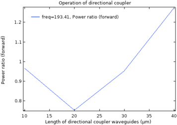
Figure 4. The ratio of the power in the upper to the lower waveguide as a function of directional coupler length.
Download figure:
Standard image High-resolution imageOptimized performance of an optical isolator is presented by the value of isolation ratio. For a device to be functionally useful, it is desired that the value of isolation ratio be as high as possible. As it is shown in figure 5(a), for a bend radius of 3.7 mm, the isolation ratio of 50 dB is achieved. In contrast, the insertion loss should be the lowest possible amount as it describes the attenuation in the forward propagation direction. According to figure 5(b), the insertion loss for the optimized bend radius is decreased to 1 dB, which is acceptable.
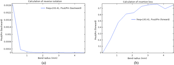
Figure 5. Calculation of the key specifications: (a) reverse isolation (b) insertion loss.
Download figure:
Standard image High-resolution imageThe key specifications are calculated based on the following formulas:


4. Numerical results
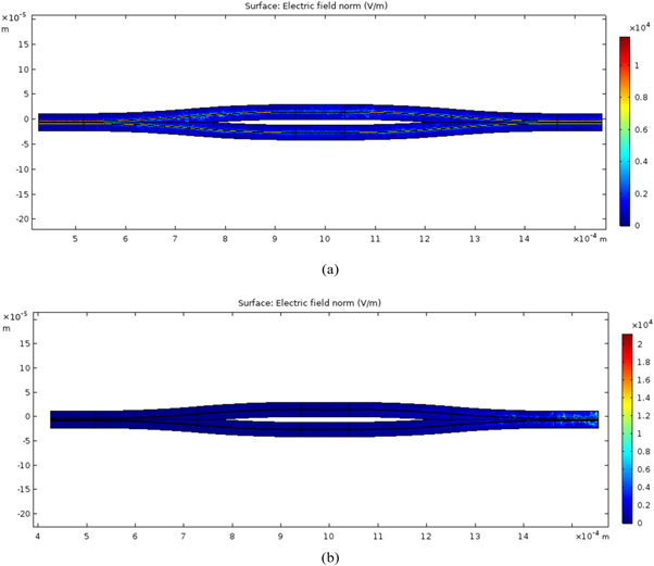
The optimized values of the interferometric optical isolator are given in table 1. Also, for future fabrication of the discussed optical isolator, it is essential to know how accurately must the dimensions be held in order to satisfy the necessary isolation requirements. Hence, the isolation ratio and insertion loss were calculated for a probable variation range, and no tangible influence on performance was evident. Figure 6 illustrates the evolution of electric field norm for forward and backward propagating waves. As seen, the forward traveling waves couple into the output port, while the backward traveling waves cannot couple into the input port. Hence, the suggested design acts as a unidirectional device, which is functionally useful as the return loss is higher than the reverse isolation. It is worth mentioning that in comparison with the illustrated design in reference number 17, not only the design parameters including the length of phase shifter arm and directional coupler length experienced a decrease of 15 μm and 28.5 μm, respectively but also the isolation ratio has increased by 10 dB.
Table 1. Design parameters.
| Parameter | Wavelength | Frequency | Total waveguide width | Core width | Length of phase shifter | Bend radius | Length of directional coupler | Package size |
|---|---|---|---|---|---|---|---|---|
| Value | 1550 nm | 1.9341E14 HZ | 30 μm | 2 μm | 90 μm | 3.7 mm | 31.5 μm | 10*60*150 μm |
Figure 6. The electric field norm for: (a) forward and (b) backward propagating waves.
Download figure:
Standard image High-resolution image
5. Conclusion
In this paper, we have designed, simulated and optimized an interferometric optical isolator based on a magneto-optic Mach–Zehnder with YIG waveguide. Propagation constants of the waveguide structure were obtained through the Boundary Mode Analysis. The length of reciprocal and nonreciprocal phase shifters and the radius of curvature were calculated to cut down the insertion loss in the forward path while providing a high reverse isolation and return loss in the backward path. Scattering Boundary Condition has been chosen to make boundaries transparent for scattered waves and another boundary condition was also selected to specify the tangential component of the magnetic field. Finally, by optimizing the design parameters, including phase shifter length, bend radius and directional coupler length, an optical isolator with 50 dB isolation ratio and 1 dB insertion loss was achieved.