

Abstract
The investigation of conductive silver pastes and inks has witnessed extensive research within the domain of printed electronics in recent years, primarily owing to the exceptional electrical conductivity and steadfastness intrinsic to silver. This paper introduces an approach for the fabrication of stable, cost-effective, and low-resistance conductive silver paste tailored for flexible printed circuits. This method facilitates the solidification of the conductive silver paste into a highly conductive silver film at a curing temperature of 250 °C. In the process of preparing the conductive silver paste, Ag flakes is subject to modification through the incorporation of Ag NPs, which are subsequently sintered at a low temperature curing setting. The sintering of Ag NPs serves to establish connections between adjacent particles of Ag flakes within the paste, thereby enhancing the conductivity and flexibility of the resulting conductive printed silver film. When the ratio of Ag NPs to Ag flakes is maintained at 10:90, the volume resistivity of the Ag NPs-modified film registers at 2.7 × 10⁻⁵ Ω.cm. This demonstrates a substantial 53.45% reduction in the volume resistivity of the conductive printed silver film modified with Ag NPs, compared to its Ag NPs-absent counterpart. Post 200 cyclic bending tests, it becomes evident that the resistance change rate in the Ag NPs-modified conductive printed silver film is a mere 12.5%, whereas the Ag NPs-modified silver film lacking Ag NPs displays a resistance change rate of 21.5%. This discrepancy underscores the capacity of Ag NPs-modified Ag flakes to fortify the bending resistance of the conductive printed silver film. Comprehensive data analysis substantiates that the improvements in electrical conductivity and bending resistance can be attributed to the superior bridging facilitated by the sintering process on the surface of the Ag NPs-modified Ag flakes.
Export citation and abstract BibTeX RIS

Original content from this work may be used under the terms of the Creative Commons Attribution 4.0 licence. Any further distribution of this work must maintain attribution to the author(s) and the title of the work, journal citation and DOI.
1. Introduction
In the wake of the swift evolution of electronic functional devices, electronic products have raised increasingly demanding criteria for the production process. These requirements encompass attributes such as lightweight construction, cost-effectiveness, elevated performance, and ecological sustainability. The preparation of novel printable conductive materials faces fresh challenges in response to these demands. The domain of printed electronic technology, a rapidly advancing facet of electronics, has garnered growing attention in everyday life [1–5]. At present, conductive paste and conductive ink represent the foundational constituents of virtually every printed electronic material. Their relevance spans from the inception of printed circuit boards to the emergence of flexible circuits in recent years [6]. Silver, characterized by its status as the pure element boasting optimal electrical conductivity at room temperature, possesses attributes such as exceptional electrical conductivity, robust resistance to oxidation in atmospheric conditions, and stable optical and chemical characteristics, contingent upon its size, composition, and morphology [7]. Consequently, silver finds extensive utility in the realm of printed electronic materials, ranging from low-cost thin film switches, solar cells, electroluminescent devices, sensors, conductive adhesives, and conductive films to circuits, thin film transistors, and radio frequency identification (RFID) tags [8–11].
The processing of printed electronics, rooted in graphic art techniques encompassing screen, gravure, adagio, stencil, and inkjet printing [5], facilitates the manufacture of electronic products on flexible substrates. Printing on flexible substrates bears the merits of cost-efficiency and high throughput, attributable to its additive nature [12, 13]. Furthermore, the flexibility of the substrate permits the application of conductive paste on substrates of any shape or the alteration of the substrate's form as needed. However, amid the evident advantages of flexible substrates, the printing process poses specific considerations. Notably, the rheological characteristics of the conductive paste or conductive ink must align with those of the printing substrate. Achieving this is typically accomplished by leveraging the thixotropy and pseudoplasticity induced by solvents and additives within the conductive paste, ensuring optimal fluidity for printing and dimensional stability post-printing. For flexible electronic devices, cost-effective substrates are frequently heat-sensitive materials, such as polyethylene terephthalate (PET film) with a process temperature range typically not exceeding 200 °C, and polyimide films (PI films) capable of withstanding process temperatures reaching 300 °C. Importantly, these temperature thresholds significantly fall below the melting point of silver metal. Given these thermal constraints, there is a pronounced interest in developing highly conductive silver pastes that can be processed at low curing temperatures, substantially below the melting temperature of silver and the temperature thresholds of polymer substrates. Such formulations aim to achieve superior electrical conductivity and bending flexibility.
Currently, micrometer-scale Ag flakes, owing to its exceptional characteristics, is frequently utilized as the primary conductive component material in commercial conductive silver pastes. At low curing temperatures, it effectively diminishes the inter-particle contact area in the paste, thereby reducing the contact resistance [14, 15]. Zhe et al employed 1-hexanol as a solvent to prepare a low-temperature conductive silver paste, achieving a volume resistivity of (4.2 ± 0.8) × 10−5Ω·cm after curing at 175 °C [16]. Research indicates that the addition of highly conductive Ag NPs to micrometer-scale Ag flakes based conductive silver pastes can effectively decrease the contact resistance [17, 18]. Ag NPs possess higher surface energy, leading to a significant reduction in the melting point at the nanoscale. This nano-effect further decreases the sintering temperature of conductive inks, enabling metalization at lower temperatures and consequently providing lower resistance [19]. Chen S et al prepared a silver-plated copper foil by in situ generation and sintering of Ag NPs during curing, filling various isotropic conductive adhesives (ICA), resulting in a volume resistivity of 9.6 × 10⁻⁴Ω·cm [20]. Meng et al modified Ag flakes with Ag2O NPs to create an ink with high conductivity, Under low-temperature conditions of 150 °C, Ag2O NPs sintered, bridging the Ag flakes and yielding an ink with a volume resistivity of 1.5 × 10⁻⁵Ω·cm [21]. Therefore, we believe that modifying Ag NPs on the surface of Ag flakes powder to enhance the conductivity of conductive silver pastes is feasible.
In this paper, through a simple chemical reduction method, Ag NPs and Ag flakes are combined, so that Ag NPs and Ag flakes form a 'whole'. This approach involved the preparation of Ag NPs/Ag flakes composite silver powder as a basis for formulating low-temperature conductive silver pastes, thus yielding a novel and stable composite low-temperature conductive silver paste. This composite silver paste effectively reduces the presence of free Ag NPs in the paste, ensuring that more Ag NPs is situated on the surface of the Ag flakes powder. Moreover, it mitigates the aggregation phenomenon among Ag NPs. During the low-temperature curing stage of the Ag NPs/Ag flakes composite conductive silver paste, the conducive conditions allow for the sintering of Ag NPs in the paste. Through the sintering of Ag NPs, additional conductive pathways are formed between the Ag flakes, thereby reducing the resistance between micrometer-scale Ag flakes. This leads to an overall enhancement in the conductivity of the conductive silver paste. The schematic diagram of the sintering process of Ag NPs during the low-temperature curing stage is depicted in figure 1. In the optimization experiments, the relationship between the content of Ag NPs and the volume resistivity of the printed and cured films was evaluated by varying the mass ratio of Ag NPs to Ag flakes. Additionally, the influence of Ag NPs-modified Ag flakes on the flexural strength of the printed conductive material was assessed through flexural testing.
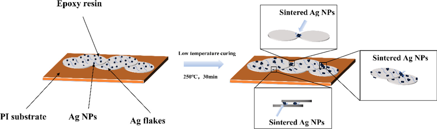
Figure 1. Schematic diagram of the sintering process of Ag NPs during the low-temperature curing stage.
Download figure:
Standard image High-resolution image2. Experiment
2.1. Materials
AgNO3 was procured from Shanghai Xugong Fine Chemical. Micron-scale Ag flakes powder was acquired from Deli Chemical Research Institute Co., Ltd. Epoxy resin was sourced from Wuhan Kamik Technology Co., Ltd. The latent curing agent, boron trifluoride monoethylamine complex, DBE solvent, NH4.H2O, NaBH4, and lauric acid were obtained from Shanghai Aladdin Biochemical Technology Co., Ltd.
2.2. The creation of composite silver powder comprising Ag NPs and Ag flakes
Initially, adhering to the mass ratio permutations of 5:95, 10:90, 15:85, and 20:80 (for instance, Ag NPs: Ag flakes = 10:90), 0.2 g of AgNO3 and 1.134 g of Ag flakes powder were separately dissolved in 200 ml of deionized water. The AgNO3 aqueous solution underwent gradual addition of ammonia water until clarification was achieved. Subsequently, 1.5 ml of concentrated ammonia water and 0.375 g of lauric acid were introduced into the aqueous solution of Ag flakes, and the resulting mixture underwent ultrasonic treatment for a duration of 30 min. This ultrasonication served to ensure complete dispersion of the Ag flakes within the solution. Upon the conclusion of ultrasonication, the Ag flakes solution was subjected to magnetic stirring on a magnetic stirrer, operating at a speed of 600 r min−1. During the stirring process, the prepared AgNO3 mixed solution was gradually incorporated into the Ag flakes mixed solution.
Following the addition of the AgNO3 solution, a 2.5 ml solution of 0.5 mol/L NaBH4 was gradually introduced into the mixed silver solution. Comprehensive stirring induced a transformation of the solution from gray to black. Subsequently, phosphoric acid was incorporated into the mixed silver solution to regulate the pH to 6. The freshly prepared mixed solution then underwent magnetic stirring in an ice bath at a speed of 600 r/min for a duration of 12 h. Upon completion of the stirring process, the upper layer solution was decanted, and the residual material underwent washing with anhydrous ethanol, a procedure that was repeated 3–5 times. Subsequently, the washed sediment was subjected to vacuum drying in an oven at 70 °C for 12 h, yielding white Ag NPs/Ag flakes composite silver powder. The overall reduction of Ag NPs in the process adheres to the following reaction equations: (1)–(3).


2.3. The formulation of conductive silver paste
With regard to epoxy resin, the solvent mass ratio of DBE was configured at 40:60. Both substances were combined in a beaker, following which 5% of the total mass of the mixture was introduced as the latent curing agent, specifically, boron trifluoride monoethylamine complex. Subsequently, the mixture underwent heating and stirring using a water bath with a rotational speed set at 300 revolutions per minute, a water bath temperature fixed at 50 °C, and a stirring duration of 1 h. This process yields the requisite organic carrier for the preparation of conductive silver paste, which is subsequently stored at temperatures between 2–8 °C.
The organic carrier, produced as described above, is amalgamated with Ag NPs/Ag flakes composite silver powder in a mortar, in accordance with a mass ratio of 35% to 65%, until the silver powder becomes thoroughly wetted. This process culminates in the production of semi-finished silver paste. The semi-finished silver paste undergoes rolling 3–5 times in a three-roll mill, leading to the creation of the mixed finished Ag NPs/Ag flakes composite silver powder silver paste. This paste is employed in screen printing technology for subsequent characterization testing on polyimide film.
2.4. Characterization method
Field emission scanning electron microscopy (FE-SEM, Sirion XL30, FEI) was employed to observe the surface and cross-sectional morphology of the silver film following the curing of the silver powder. For higher magnification details, transmission electron microscopy (TEM, Tecnai G2-TF30) was utilized. The composition of the silver powder was assessed through x-ray diffraction (XRD, D8 Advance, Bruker). The components of the silver film were analyzed using EDS analysis. The sintering temperature of the Ag NPs within the composite silver powder was determined through differential scanning calorimetry (DSC). The square resistance of the silver film was measured using a four-probe instrument, and the square resistance was subsequently calculated based on the film thickness. The volume resistivity of the silver film was derived through the formula R = ρ/h (where R represents the square resistance, ρ signifies the volume resistivity, and h denotes the film thickness). The assessment of resistance changes in the conductive printed film post-bending tests was conducted using a multimeter.
3. Results and discussion
Initially, composite silver powders with varying Ag NPs contents were meticulously synthesized. The AgNO3 solution underwent direct reduction to form Ag NPs through a chemical reduction method, reduced on the micron-scale surface of Ag flakes, utilizing the prepared silver-ammonia complex as the precursor. In figure 2(a), the SEM image presents the original micrometer-sized Ag flakes. Predominantly, these original micrometer Ag flakes exhibit a particle size ranging from 3 to 5 μm, featuring a polished and sleek surface. Upon the completion of the reduction reaction, numerous small particles became observable on the Ag flakes' surface, providing initial confirmation of the successful attachment of Ag NPs to the Ag flakes' surface, as illustrated in figures 2(b), (c), and (d). With the increase of Ag NPs content, the particles on the surface of the Ag flakes powder gradually increased. The Ag NPs transitioned from being scattered on the surface of the Ag flakes powder to being uniformly dispersed, eventually leading to excessive agglomeration. At the Ag NPs and Ag flakes ratio of 10:90, the Ag NPs exhibit uniform dispersion on the surface of the Ag flakes powder without agglomeration. Consequently, the subsequent formulation of composite silver powder selects the Ag NPs and Ag flakes ratio of 10:90 to prepare the conductive phase of the silver paste.
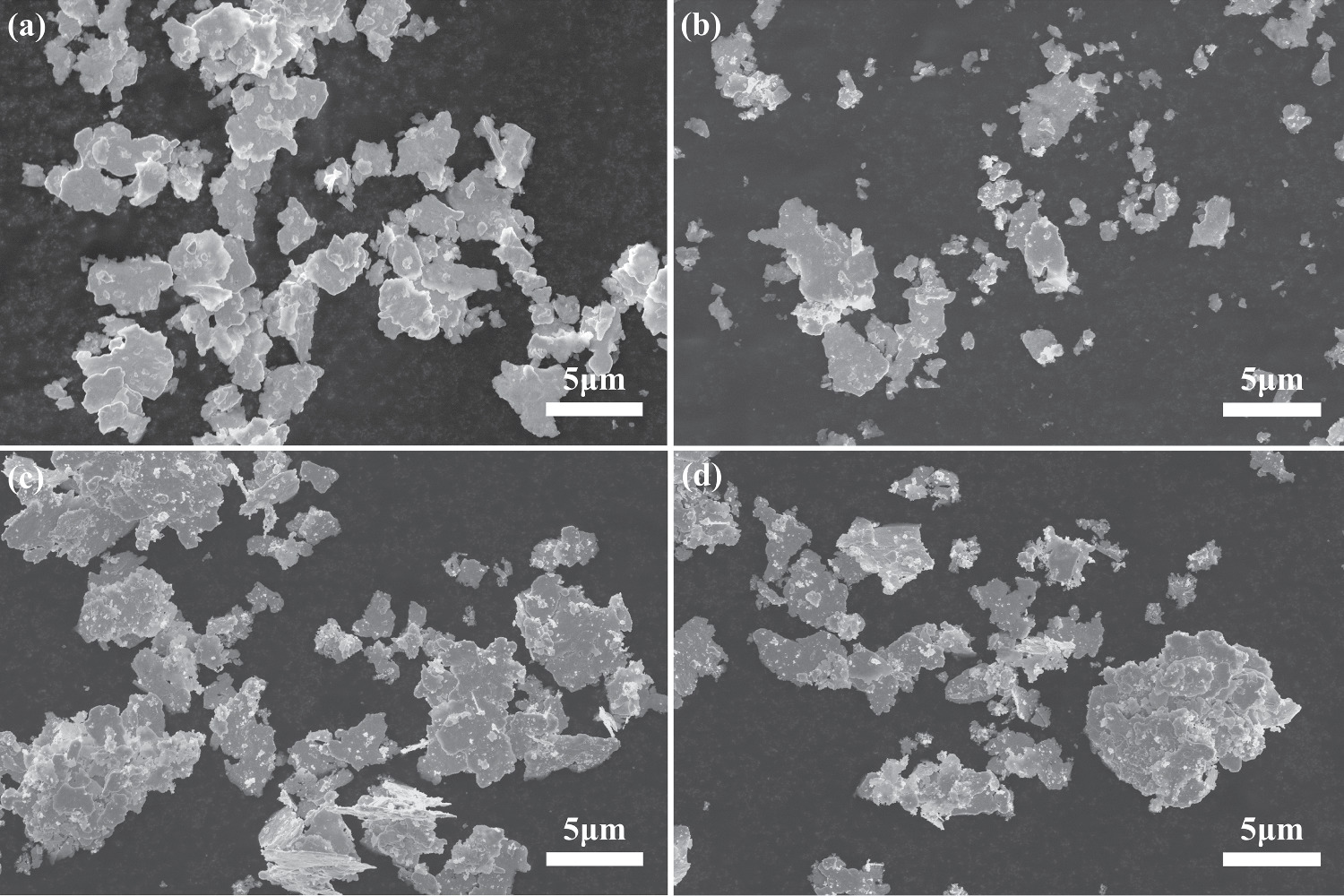
Figure 2. Characterization of Ag NPs/Ag flakes composite silver powder (a) SEM image of flake silver powder (b) SEM picture of mAg NPs: mAg flakes = 5:95 composite silver powder (c) SEM picture of mAg NPs: mAg flakes = 10:90 composite silver powder (d) SEM picture of mAg NPs: mAg flakes = 20:80 composite silver powder.
Download figure:
Standard image High-resolution imageFrom the SEM imagery of the aforementioned composite silver powder, it is discernible that when the mass ratio of Ag NPs to Ag flakes is 10:90, the Ag NPs exhibit a uniform distribution. This ratio of composite silver powder is chosen for TEM analysis. As depicted in figures 3(a) and (b), it is evident that Ag NPs are evenly dispersed on the surface of Ag flakes, with the size of Ag NPs predominantly falling within the range of 10–30 nm. This smaller particle size of Ag NPs can be sintered at curing temperatures. Through the HRTEM image in figure 3(d), it can be observed that there are different binding conditions between Ag NPs, as shown in the area framed by the red dotted line. Ag NPs are connected by grain boundaries, with (111) crystal faces on both sides of the grain boundaries, and the Angle between the crystal faces is 94°, indicating that the two Ag NPs grow together. The Ag NPs are spatially segregated by distinct bright lines, as illustrated in the region demarcated by the yellow dashed lines, and their cohesion may be attributed to adsorption phenomena. In the area enclosed by the blue dashed lines, it is evident that there is an overlap between the lattice of Ag flakes and Ag NPs, exhibiting a relatively clear appearance devoid of gray shadows or conspicuous separation. This observation implies a high likelihood of Ag NPs growing on the surface of the Ag flakes.
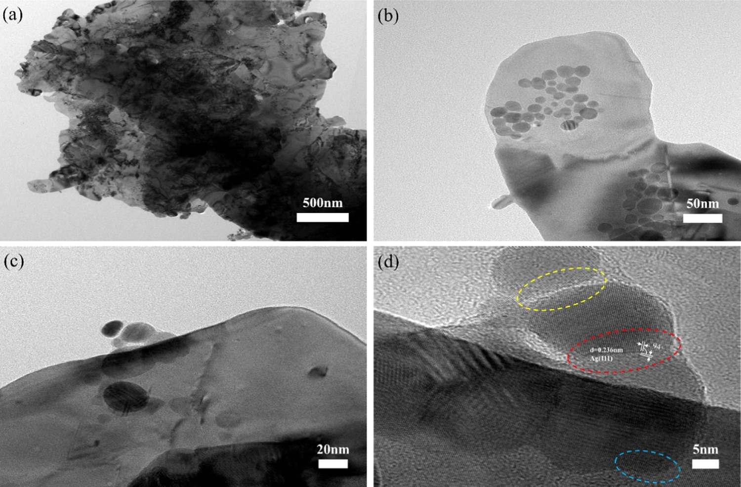
Figure 3. (a) mAg NPs: mAg flakes = 10:90, TEM (b) mAg NPs: mAg flakes = 10:90 locally enlarged TEM image (c) TEM of Ag NPs growing on the surface of Ag flakes (d) HRTEM of Ag NPs grown on the surface of Ag flakes.
Download figure:
Standard image High-resolution imageIn the study, lauric acid was employed as a coating agent, while phosphoric acid was used to adjust the pH value. When the solution exhibited weak acidity (with a pH value between 4 and 6), lauric acid played a role in limiting the size of the Ag NPs on the surface of the Ag flakes powder. The reaction solution was prepared with a pH value ranging from 8 to 9, so the addition of phosphoric acid was used to adjust the pH of the reaction solution to the range of 4 to 6. The purpose of restricting the growth of the Ag NPs is to ensure that the sintering temperature of the Ag NPs meets the requirements for preparing low-temperature silver paste. The larger the size of the Ag NPs, the higher the thermal energy required for the sintering process, leading to higher sintering temperatures. However, excessively high temperatures contradict the concept of low temperature. Therefore, it is necessary to control the sintering temperature of the Ag NPs and thus limit their size. As shown in figure 3(b), the majority of the Ag NPs had diameters ranging from 10 to 30 nm.
Figure 4(a). displays the x-ray diffraction (XRD) pattern of Ag NPs/Ag flakes composite silver powder with a mass ratio of 10:90. A comparison is made between the XRD patterns of Ag NPs/Ag flakes composite silver powder and pure Ag flakes. Notably, characteristic peaks are evident at five positions with 2θ values of 38.1°, 44.3°, 64.4°, 77.4°, and 81.5°, corresponding to crystal faces (111), (200), (220), (311), and (222), respectively. These characteristic peaks align with those of elemental silver (JPCDS-04-0783). Furthermore, the characteristic peak position of Ag NPs/Ag flakes composite silver powder, prepared by this method, does not shift when compared to that of pure Ag flakes. This indicates that no other impurities are introduced during the process of preparing the composite silver powder, and elemental silver is not oxidized to form Ag2O. Therefore, it is confirmed that no additional impurities are introduced in the process of reducing Ag NPs onto the surface of Ag flakes using the chemical reduction method described in this paper. Consequently, the Ag NPs/Ag flakes composite silver powder prepared by the above method serves as the conductive phase for the subsequent preparation of conductive silver paste.

Figure 4. (a) XRD pattern of mAg NPs: mAg flakes = 10:90 composite silver powder. (b) DSC curve of mAg NPs: mAg flakes = 10:90 composite silver powder compared to pure Ag flakes.
Download figure:
Standard image High-resolution imageThe sintering temperature of Ag NPs in the Ag NPs/Ag flakes composite silver powder is revealed through DSC curve analysis in figure 4(b). This analysis exhibits a distinct exothermic peak at 237 °C. In contrast, the DSC analysis of Ag NPS/Ag flakes composite silver powder shows no exothermic peak at 300 °C. Typically, the sintering temperature of Ag flakes falls within the range of 700 °C to 800 °C. As confirmed by the XRD pattern analysis in figure 4(a), there are no other impurities present in the Ag NPs/Ag flakes composite silver powder. Hence, the observed exothermic peak is attributed to the Ag NPs/Ag flakes composite silver powder. Importantly, this temperature aligns with the requirement of low-temperature curing (within 300 °C) in our experiment. Consequently, we have selected a curing temperature of 250 °C for 30 min, during which the Ag NPs in the Ag NPs/Ag flakes composite silver powder undergo simultaneous sintering.
Studied the influence of the mass ratio of Ag NPs to Ag flakes in the conductive silver paste prepared from Ag NPs/Ag flakes composite silver powder on the electrical conductivity. As shown in figure 5(a), when the mass ratio of Ag flakes is 5:95, there are fewer Ag NPs spheres attached to the surface of the low temperature cured Ag flakes. After sintering, the connecting effect of Ag NPs spheres on Ag flakes is limited, resulting in a limited improvement in the electrical conductivity of the conductive silver paste. When the mass ratio between Ag NPs and Ag flakes in Ag NPs/Ag flakes composite silver powder is increased to 10:90, as shown in figure 5(b), Ag NPs are evenly distributed on the surface of the Ag flakes, forming more connecting bridges between the Ag NPs and the Ag flakes. This significantly improves the conductive properties of the conductive silver paste. However, when the mass ratio between Ag NPs and Ag flakes in Ag NPs/Ag flakes composite silver powder is increased to 15:85, there is more Ag NPs on the surface of the Ag flakes, but these Ag NPs start to agglomerate, as shown in figure 5(c). With the increase of NPs content, due to the large specific surface area of Ag NPs, the wettability of the organic carrier for the composite silver powder decreases. This deteriorates the pulping performance of the finished silver paste, significantly reduces the printability of the conductive silver paste, and increases the pores in the printed conductive silver film. This hinders the formation of the conductive path and results in a deterioration of the conductive properties of the conductive printed silver film, which is an undesirable phenomenon. When the mass ratio between Ag NPs and Ag flakes in Ag NPs/Ag flakes composite silver powder is increased to 20:80, the agglomeration phenomenon becomes more pronounced, and the porosity increases significantly, as shown in figure 5(d). Comparing the four groups of Ag NPs and Ag flakes composite silver powder with different mass ratios, it can be concluded that Ag NPs are evenly distributed on the surface of Ag flakes when the mass ratio of Ag NPs to Ag flakes is 10:90. The growth of necks between Ag NPs after sintering also forms more connected bridges, and there is no noticeable agglomeration. This ratio will be selected for further characterization tests in this paper.

Figure 5. (a) SEM image of the printed silver film prepared by mAg NPs: mAg flakes = 5:95 composite silver powder. (b) SEM image of the printed silver film prepared by mAg NPs: mAg flakes = 10:90 composite silver powder. (c) SEM image of the printed silver film prepared by mAg NPs: mAg flakes = 15:85 composite silver powder. (d) SEM image of the printed silver film prepared by mAg NPs: mAg flakes = 20:80 composite silver powder.
Download figure:
Standard image High-resolution imageEDS spectrum analysis was conducted on the conductive silver film, as depicted in figure 6. The elemental distribution chart from the surface scan and the overall spectrum diagram of the surface reveal that the Ag element constitutes an overwhelmingly predominant portion in this region. The presence of carbon (C) and oxygen (O) elements can be attributed to the incorporation of organic carriers during the formulation of the conductive silver film. The organic carriers employed in this study, including epoxy resin, solvent, and latent curing agent, are primarily composed of organic compounds consisting of C, H, and O. The resin, serving as the binding phase in the low-temperature conductive silver paste, is the primary determinant of silver paste adhesion strength. During the low temperature curing at 250 °C, only the solvent in the carrier evaporates, leaving the resin within the conductive silver film. Hence, the presence of C and O elements is expected. Furthermore, there is no introduction of impurity elements into the film, further confirming the feasibility of the method used in Ag NPs/Ag flakes composite silver powder preparation and the low temperature curing process of the conductive silver paste.
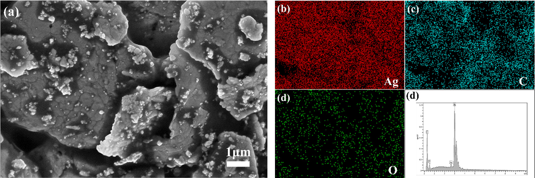
Figure 6. (a) SEM image of Ag NPs/Ag flakes composite paste (mAg NPs: mAg flakes = 10:90) printing film enlarged by 40000 x. (b) (c) (d) represent EDS spectra illustrating the distribution of Ag, C, and O elements, respectively. (e) EDS spectra.
Download figure:
Standard image High-resolution imageAn analysis of the methods for introducing Ag NPs into the silver paste reveals that direct addition of nanoparticles during the mixing phase may lead to increased solvent consumption due to their high surface area, which is unfavorable for the printing process of conductive silver paste. Moreover, a significant portion of the directly added Ag NPs may remain dispersed in the organic carrier rather than uniformly dispersed on the surface of the Ag flakes. During the sintering stage, these nanoparticles dispersed in the organic carrier may sinter directly, without ensuring that the majority of the nanoparticles sinter on the surface of the Ag flakes to form conductive pathways between them. This ineffective sintering has a minimal impact on improving the conductivity of the silver paste. Additionally, direct addition of Ag NPs may result in uneven dispersion on the Ag flakes and significant aggregation. Aggregated nanoparticles require higher temperatures for sintering, which is undesirable for low-temperature silver paste. In contrast, using Ag NPs/Ag flakes composite silver powder to prepare low-temperature conductive silver paste ensures that most of the nanoparticles are positioned on top of the Ag flakes, effectively reducing their dispersion and aggregation in the silver paste. This optimization not only improves the volume resistivity but also facilitates the printing process of low-temperature conductive silver paste. A comparison of the effects of directly adding Ag NPs and using Ag NPs/Ag flakes composite silver powder as sintering paste is illustrated in figure 7.
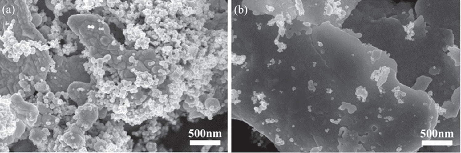
Figure 7. Comparison of methods for introducing Ag NPs (a) Direct addition of Ag NPs (b) Reducing Ag NPs onto the surface of flake silver powder.
Download figure:
Standard image High-resolution imageAfter the low temperature curing stage of Ag NPs/Ag flakes composite conductive silver paste, the sintering morphology of Ag NPs in the silver paste is depicted in figure 8(a). During the sintering process of Ag NPs, the continuous supply of heat energy prompts the formation of larger Ag NPs grains compared to the Ag NPs in their original state as silver powder, as illustrated in figure 8(a). This phenomenon results from the atomic diffusion and neck growth of Ag NPs during the sintering process. Consequently, many Ag NPs become interconnected through neck formation due to the diffusion during sintering. As a result, the Ag NPs spheres observed by FE-SEM in the conductive silver films are notably larger than those in the Ag NPs/Ag composite silver powders. The size and morphology alterations of Ag NPs before and after sintering are presented in figures 3(b) and 8(a).
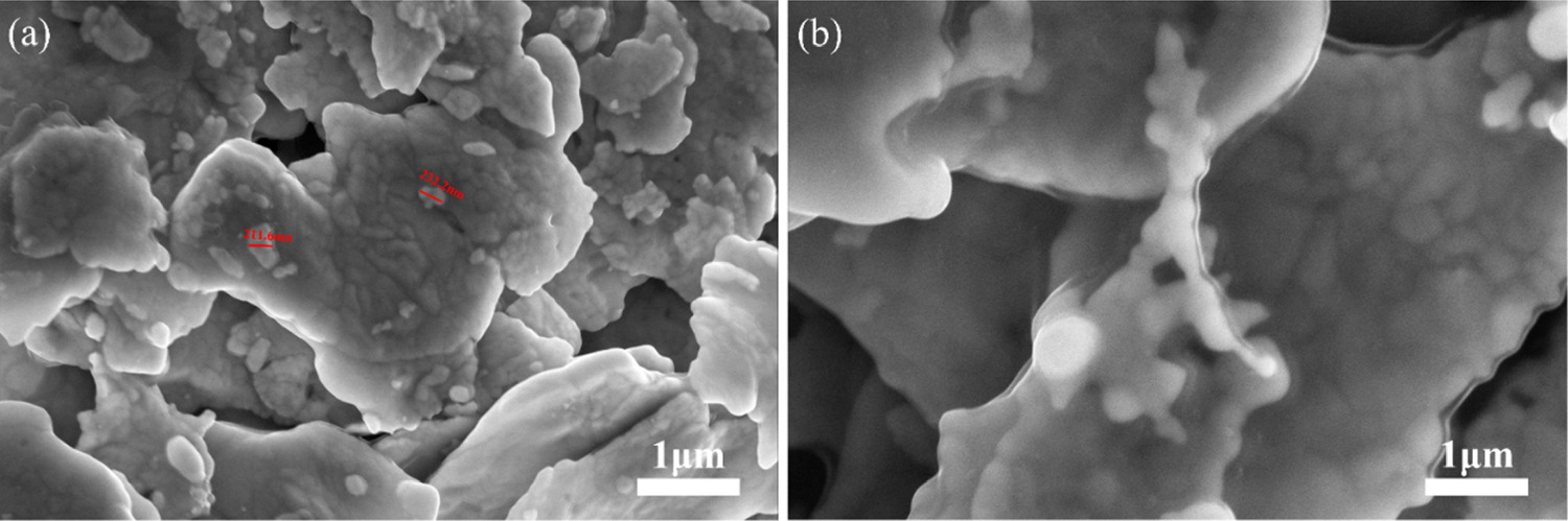
Figure 8. (a) SEM image displaying Ag NPs sintered within the conductive silver film. (b) Diagram illustrating the sintering connection of Ag NPs in the conductive silver film.
Download figure:
Standard image High-resolution imageThe SEM illustration in figure 8(b). elucidates why the sintering process of Ag NPs, during the silver film curing stage, enhances the conductivity of the conductive silver film. Following sintering at 250 °C, Ag NPs situated at the periphery of Ag flakes and those in close proximity to the edge of the Ag flakes establish connections through neck growth, facilitated by atomic diffusion, as demonstrated by the SEM image in figure 8(b). This connectivity effect exerts a positive influence on the entire conductive silver film, as it expands the intermediate conductive pathway of the entire silver film, thus engendering a new conductive route between Ag flakes, complementing the preexisting bridge contacts that form the conductive pathway. Consequently, the overall conductivity of the silver film is heightened.
Based on the aforementioned information, we conducted a comparative analysis of the impact of increasing the Ag NPs content from 0% to 20% on the electrical conductivity of the cured silver film. The thickness of these conductive silver films with varying mass ratios of Ag NPs to Ag flakes was measured using a film thickness gauge. Our measurements revealed that regardless of the different mass ratios of Ag NPs to Ag flakes, the film thickness fell within the range of 8–12 μm, which is likely attributed to the screen printing process. Utilizing the volume resistivity calculation formula R = ρ/h, we determined that the average volume resistivity of the conductive silver film produced by screen printing the composite silver paste with Ag NPs: Ag flakes ratio of 10:90 was 2.7 × 10⁻⁵ Ω.cm. In contrast, the average volume resistivity of the conductive silver film produced by screen printing pure Ag flakes based silver paste was 5.8 × 10⁻⁵Ω.cm. Notably, the former exhibited a 53.45% reduction in volume resistivity compared to the latter.
As depicted in figure 9(a), it is evident that the sheet resistance of the silver film decreases as the curing temperature increases for different mass ratios of Ag NPs to Ag flakes. At 180 °C, it is observed that pure Ag flakes outperforms composite silver powder with 10% Ag NPs, primarily because this temperature is insufficient to sinter the Ag NPs, resulting in an uneven conductive network when Ag NPs are added. However, at 250 °C, the inclusion of Ag NPs facilitates enhanced conductivity by promoting additional conductive paths between the layers and sheets through sintering. When the curing temperature exceeds 300 °C, it is apparent from figure 9(a) that the sheet resistance of the conductive silver film stabilizes. This phenomenon is attributed to the fact that the Ag NPs' sintering temperature, as established in this experiment, is 237 °C, and further heating merely expedites the curing process without significantly affecting the ultimate measured volume resistivity of the silver film. This reaffirms the beneficial influence of Ag NPs particle sintering on the conductivity of the conductive silver film in this study.

Figure 9. (a) Variations in the volume resistivity of conductive printed silver film at different temperature ratios (b) Changes in the resistance of conductive printed silver film at different bending cycle counts.
Download figure:
Standard image High-resolution image
Flexural resistance is a critical consideration for flexible electronics. The bending experiment conditions in this study are as follows: after low-temperature curing is complete, with the center of the silver film pattern as the focal point, force is gradually applied to the ends of the conductive silver film by hand, causing the conductive silver film to bend. The portion of the conductive silver film in contact with the fingertip is taken as the endpoint. After the two endpoints come into contact with each other, the force applied by hand is slowly withdrawn. The silver film is then allowed to restore, completing one full bending cycle. An experimental comparison was conducted between the conductive silver film printed using pure Ag flakes paste and the film printed using composite silver powder paste with a mass ratio of Ag NPs: Ag flakes = 10:90. The results are presented in figure 9(b). The conductive silver film printed with unmodified silver paste exhibits low bending durability, with significant resistance fluctuations after 50 bending tests. After 200 bending tests, the resistance has increased by 21.5% compared to its non-bent state. In contrast, the silver film printed with Ag flakes = 10:90 experiences no resistance change after 50 bending cycles, and even after 200 bending tests, the resistance only increases by 12.5% compared to the non-bent state.
4. Conclusion
In summary, this study introduces a novel synthesis method for producing conductive silver paste, modified with Ag NPs. This method is utilized to create printed conductors characterized by low volume resistivity and exceptional flexibility. The approach involves the reduction of Ag+ ions within a silver-ammonia complex to Ag NP using the potent reducing agent NaBH4. These ag are attached to and deposited on the surface of Ag flakes, with Ag NPs enveloped by lauric acid to prevent uncontrolled growth (Ag NPs/Ag flakes composite silver powder maintains Ag NPs with sizes < 60 nm). Subsequently, these Ag NPs/Ag flakes composite silver powders are integrated into a printable electronic conductive paste as a stable conductive filler. Upon curing and sintering the conductive silver film at a temperature compatible with both low temperature curing and the temperature tolerance of the PI substrate, additional conductive pathways are formed between the Ag flakes through the sintering of the reduced Ag NPs. This optimization enhances the performance of the printed conductor. By controlling the mass ratio of Ag flakes to Ag NPs, we identify the optimal ratio that achieves the lowest volume resistivity. Under the conditions of Ag flakes = 10:90, the average volume resistivity of the conductive silver film is 2.7 × 10⁻⁵ Ω.cm. When compared with conductive silver films printed using pure Ag flakes paste, improvements are observed in both volume resistivity and bending resistance.
Acknowledgments
This research was funded by the Major Science and Technology project of Yunnan Province, Grant Number 202102AB080008; the Science and Technology projects of Yunnan Precious Metals Laboratory, Grant Number YPML-2022050207 and YPML-2023050206; the Fundamental Research Project of Yunnan Province-General Project, Grant Number 202001AT070061 and 2019HB108.
Data availability statement
All data that support the findings of this study are included within the article (and any supplementary files).
Declaration of competing interest
The authors declare that they have no known competing financial interests or personal relationships that could have influenced the work reported in this paper.