
Abstract
To achieve a durable, rigid, and lightweight construction material, a new class of Camellia sinensis/Ananas comosus fiber-enhanced corrugated sandwich panel was designed and produced. The crushed core layer comprises sinusoidal corrugation and is manufactured by a method of mould pressing in an attempt to assess this material's sound absorption ability. In addition, the influence of airgap and micro perforation on sound absorption properties was investigated. The samples with a greater perforation ratio and air gap are found to have a noise reduction coefficient (NRC) of 0.745, which can be used to attenuate mid- and high-range frequencies in industrial environments.
Export citation and abstract BibTeX RIS

Original content from this work may be used under the terms of the Creative Commons Attribution 4.0 licence. Any further distribution of this work must maintain attribution to the author(s) and the title of the work, journal citation and DOI.
Introduction
Due to its inherent properties such as high specific strength and rigidity, the lattice configuration of fiber-reinforced composites with synthetic fibres has been extensively investigated over the past few years [1–5]. In view of this, Fan et al [6] used glass fibres to fabricate a sandwich structure and studied its failure behaviour, concluding that its mechanical properties were significantly superior to those of a single-layer structure [7]. Similarly, Sebaey and Mahdi [8] analysed the fracture strength and delamination of pyramidal carbon fibre lattices. The conclusion of this study was that the structure of multiple layers with varying relative densities led to greater energy absorption [9]. Likewise, Fan et al [10] developed a novel configuration for the orthogonal corrugated grid that can serve as the core for significantly reducing the node stress levels by reinforcing it with Nylon. According to the study, structures with larger wave patterns absorb energy more efficiently [11]. In addition, the interlocking technique produces superior reinforcement compared to conventional wave structure processing [12, 13].
Man-made fibres make the lattice structure lighter and stronger, and the interaction of the core region permits secondary formation and application of the core layer structure. Due to these attributes, the lattice structure has excellent application potential. However, industrialising raw materials (particularly carbon fibres) and complex preparation processes is more expensive and difficult [14]. The design of materials and structures is not only concerned with performance but also ensures effective cost management [15]. Due to their low cost, environmental friendliness, biodegradability, and sound insulation, natural fibres are gaining popularity [16, 17]. The annual demand for natural fibres in plastic composites continues to increase at a rapid rate [18]. Natural fibre composites can effectively reduce the energy required for production in numerous industries, and the annual demand for natural fibres in plastic composites continues to grow at a rapid rate.
Petrone et al [19] utilised short flax fibres and continuous flax fibres for the fabrication of ultrasonic honeycomb cores and described their impact-induced mechanical behaviour. The study indicates a 15.94% improvement in the impact properties. Likewise, Boccarusso et al [20] utilised jute fibres to produce lightweight mesh structures and demonstrate the desired effects of natural composite fibres. It indicates that the addition of jute/wool increases the material's strength and makes it suitable for honeycomb structures. In summary, biomaterials have great application potential due to their noise reduction, degradation, and superior mechanical properties.
Utilizing natural fibres in unidirectional, short, and particulate form is more economically and environmentally beneficial. Recent research has focused primarily on developing typical sandwich building models and eliminating the undesirable discontinuity of the composite structure's core space. Using natural fibres such as pineapple leaf fibre (PALF) in unidirectional form, waste tea leaf fibre (WTLF) in particulate form with the minimum inclusion of glass fiber (synthetic fiber), this study aims to develop a sandwich sinusoidal corrugated structure (WTLF) to evaluate the acoustical properties by varying the micro perforation ratio and air gap thickness.
In recent years, structural designers have progressively preferred trapezoidal and sinusoidal corrugations. Because it tends to increase the resistance to flexural and shear stresses. Consequently, its use in structural applications results in reduced seismic stresses and lighter substructures, which facilitates economical and simple construction [21]. Even with less need for stiffeners, the sinusoidal corrugated structure has superior out-of-plane stiffness and shear buckling resistance compared to the flat plate, resulting in significant material and labour cost reductions during fabrication. Also, it has numerous engineering applications and benefits due to its superior strength, reduced weight, and attractive appearances.
Elgaaly et al [22] stated that sinusoidal corrugation was superior to trapezoidal corrugation because of its smoother shape. In addition, they also stated that the depth of corrugation wave, weigh length, and web thickness can be used to define the shape parameters for the design of a sinusoidal corrugated web. When the web (core) slenderness ratio increased, the ultimate load-carrying capacity increased in the sinusoidal structures [23]. In along with having a bending property, this structure is intrinsically stretchable due to its sinusoidal corrugation, and multiple cycles may further increase the linkage's flexibility for tuning the stretching stiffness [24].
Kang et al [25] conducted experiments with both sinusoidal and trapezoidal perforated corrugated cardboard (PCC). The result revealed that the noise reduction coefficient (NRC) of sinusoidal and trapezoidal PCC is 0.346 and 0.307. In a similar way, Jin et al [26] fabricated lightweight sound-absorbing meta structures with perforated fish-belly panels in order to examine its sound absorption properties. According to the investigation, the NRC of this sandwich panel is 0.423.
Fu et al [27] also conducted an analytical study of sound transmission through corrugated core functionally graded materials sandwich plates containing porous material. The study concludes that NRC values will increase as the ratio of liner-to-core-to-liner increases. In addition, the increase in cavity height has a significant impact on the porous material's ability to absorb sound waves. With the results obtained in many literatures, the sinusoidal sandwich structure is selected for fabricating PTGE based SCSP.
Materials and methods
Need for corrugation
Corrugation, which generally refers to a pattern of parallel ridges and furrows, has also been viewed as an effective method for building lightweight structures. Due to their high anisotropy, buckling resistance, and energy absorption capacity, corrugated structures have recently been utilised in a variety of industrial and academic applications. As shown in figure 1(a), corrugated structures include corrugated pipes, corrugated sheets, and corrugated panels. In general, corrugated structures are produced by folding, moulding, or any other technique. As shown in figure 1(b), a corrugated sandwich panel is a sandwich structure formed by combining two face sheets (liners) with a corrugated sheet (core or fluting). Typically, a sandwich structure is composed of two or more distinct materials, each with its own properties. Furthermore, the various material combinations have the potential to enhance the outcomes. Sandwich structures with corrugations have a substantial effect on engineering applications due to their superior structural properties.

Figure 1. (a) Examples of corrugated structures (b) corrugated sandwich panel.
Download figure:
Standard image High-resolution imageClassification of sandwich core structure
The structure design is the initial phase of designing of creative sandwich structure. According to the core layer construction standards, sandwich structures are typically classified as honeycomb, foam, corrugated, or truss core as illustrated in figure 2. In addition, a variety of sandwich core structure examples, including open stochastic cells, closed stochastic cells, honeycomb structures, prismatic topologies, and lattice truss architectures are depicted in figure 3.
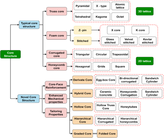
Figure 2. Classification of sandwich structures.
Download figure:
Standard image High-resolution image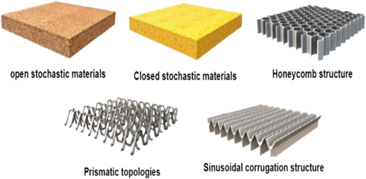
Figure 3. Examples of core shapes for sandwich structures.
Download figure:
Standard image High-resolution imageDesign of PTGE based SCSP
In this work, PTGE (Pineapple/Tea/Glass/Epoxy) based Sinusoidal Corrugated Sandwich Panel (SCSP) was designed and depicted in figure 4. The parameters that influence the sound absorption properties (SACs) of SCSP include the angle of incidence, distance between the sinusoidal, layer thicknesses, and core height are tabularized in table 1.
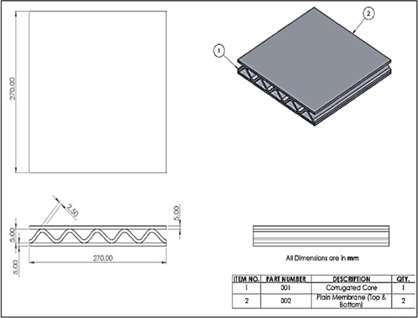
Figure 4. Geometrical dimensions of PTGE based SCSP.
Download figure:
Standard image High-resolution imageTable 1. Parameters of PTGE based SCSP.
| S. no | Parameter | Values |
|---|---|---|
| 1 | Angle of incidence | 0° |
| 2 | Distance between sinusoidal | 50 mm |
| 3 | Thickness of the core layer | 5 mm |
| 4 | Height of the core layer | 5 mm |
| 5 | Total thickness of the composite | 15 mm |
| 6 | Size of the composite | 270 × 270 mm2 |
The PTGE based NFRHCs are planned with a 5 mm thickness and seven plies, each of which is segmented into 0.71 mm parts. In addition, for achieving a homogenous mixture of fibres, the length and diameter of fibres must be chosen appropriately, as shown in table 2. Similarly, the placement of suitable fiber within plies is a crucial aspect in attaining superior sound absorption. Therefore, the outer layers (1st and 7th ply) must be sufficiently strong to endure the entire applied load, and failure may occur first on either the 1st or 7th ply. From various literatures, it is proven that the synthetic fibres have a better load capacity than natural fibres. As demonstrated in figure 5, glass fibres are chosen for the outer layers to increase the strength of the interply hybrid composites. Due to the synthetic nature of the particular ply, its fabrication was facilitated, yet its slightly tortuous path permits sound waves to pass through it with minimal effort. Therefore, the outer layer (glass fibre) will have less sound absorption.
Table 2. Physical properties of T-PALF, T-WTLF and Glass fibers.
| Fibre properties | Units | Values |
|---|---|---|
| T-PALF | ||
| Length | mm | 4–8 |
| Diameter | μm | 8–17 |
| Density | g/cc | 1.526 |
| T-WTLF | ||
| Length | mm | 1.1–1.8 |
| Diameter | μm | |
| Density | g/cc | 1.08 |
| E-Glass fiber | ||
| Length | mm | 4.7–5.4 |
| Diameter | μm | 8.2–16.2 |
| Density | g/cc | 2.586 |
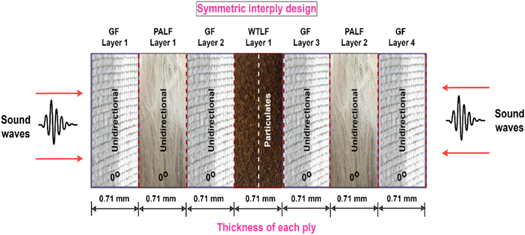
Figure 5. Symmetric interply design of PTGE based NFRHCs.
Download figure:
Standard image High-resolution imageImmediately adjacent to the glass fibre, a natural fibre with more microfibrils is introduced in order to improve sound absorption. Therefore, T-PALF is selected which exhibits increased microfibrils when subjected to an alkaline treatment and utilised as a unidirectional natural fibre. When incident sound waves travel via the poor tortuous path of glass fibres and reach the T-PALF ply, they are impeded by approximately 60% due to its moderately rigid tortuosity.
In order to improve the rate of sound absorption, the core layer (4th ply) was made using T-WTLF. Due to the core layer's high porosity, all sound waves that escape through the first three plies are totally absorbed by the core. When T-WTLF is integrated into an epoxy matrix, its particle nature creates a highly porous structure with difficult, sinuous pathways. As seen in figure 5, due to their symmetry, these are capable of controlling sound waves on both sides. In addition, certain sound waves are converted into thermal energy by all plies.
Fabrication of PTGE based SCSP
The desired compositions of 25% by weight of T-WTLF (5% alkali treated WTLF), 5% by weight of T-PALF (5% alkali treated PALF), and 10% by weight of glass fibers with 60% by weight of epoxy were employed to fabricate the liners (face sheet) and flute (core) layers using compression moulding and hand layup, with a fiber to matrix ratio of 40:60. The well-blended epoxy and hardener were applied to the laminas in a 10:1 ratio. For the fabrication of the liners, a square mould with a surface area of 270 × 270 mm2 and a thickness of 5 mm was utilized. The fibers were evenly dispersed according to the lamina sequences in the mould box, and the matrix was then applied on top. Air bubbles were eliminated from lamina using a mild steel roller till the desired thickness was obtained. The mould was then squeezed at a pressure of 40 kgf cm−2 in a compression moulding machine to remove unwanted excessive air bubbles, and the composites were allowed to cure at room temperature. Liner 1 and 2 (top and bottom face sheet) were obtained after 2 h of curing.
The designated compositions of 25% by weight of T-WTLF, 5% by weight of T-PALF, and 10% by weight of glass fibers with 60% by weight of epoxy resin were placed into the corrugated mould as per the lamina sequence and then manually pressed and rolled with a mild steel roller to remove the air bubbles and achieve required thickness of corrugated core. The material is then allowed to solidify at 120 °C for four hours to produce a corrugated sinusoidal core.
As depicted in figure 6, the current effort involves the two processes of combining the liners and flute in order to fabricate the PTGE based SCSP. This fabrication strategy was applied to prevent epoxy resin from seeping into the sinusoidal corrugated core, to guarantee the uniform thickness of the top and bottom skins (liners), and to build a strong bond between the liners and core.
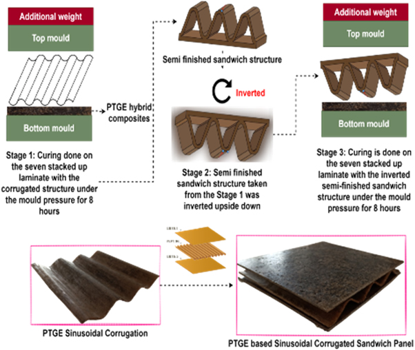
Figure 6. Fabrication of PTGE based SCSP.
Download figure:
Standard image High-resolution imageInitially, T-PALF, T-WTLF, and glass fibers were spread uniformly according to the sequence depicted in figure 6, and the well-mixed matrix (Epoxy LY556 and hardener HY951) was coated on each lamina in the ratio of 10:1. Using a mild steel roller, the air bubbles generated in the lamina during the coating of epoxy resin were eliminated.
The compressive pressure applied during the compression moulding process for SCSP is a crucial factor. The interfacial adhesion between the matrix and fiber is significantly enhanced by high-pressure compression moulding [13]. Nevertheless, it is essential to remember that increasing the press capacity over 50 kgf cm−2 may cause damage to the fiber structure, hence impairing their mechanical qualities. As depicted in figure 6, the stacked lamina was compressed to the desired thickness by applying a pressure of 35 kgf cm−2 at room temperature in a compression moulding machine.
In addition to temperature and pressure, the holding or curing time is crucial for SCSP compression moulding. Insufficient holding time can lead to defects in composite samples. Previous studies have recommended an average holding time of two to three hours for the compression moulding of hybrid composites containing natural fibers. This also helps natural fibers function as a potential composite reinforcement [14]. Therefore, after 3 h of holding period, the manufactured PTGE based SCSP were extracted from the mould cavity.
Preparation and sound absorption testing of PTGE based SCSP
The two-microphone impedance test tube method was used in accordance with ASTM E1050-10 to determine the sound absorption properties of PTGE based SCSP samples. This setup for measuring sound absorption utilised the Brüel & Kjaer 4206 and 4187 microphones, the Brüel & Kjaer 3560C analyzer, and the Brüel & Kjaer 276C power amplifier to determine the SACs at various frequencies. The small tube with a sample holder having a diameter of 29.5 mm and the larger tube with a sample holder having a diameter of 99.5 mm were utilised to calculate the sound absorption coefficients between 63 Hz and 6300 Hz. As illustrated in figures 7, 29.5 mm and 99.5 mm PTGE based SCSP samples were prepared to fit small and large tube sample holders, respectively.
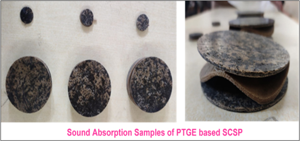
Figure 7. Sound absorption samples of PTGE based SCSP.
Download figure:
Standard image High-resolution imageDesign of micro-perforated sound absorption samples of PTGE based SCSP
In order to increase the SACavg and NRC rate of these PTGE based SCSP, the face sheets were micro-perforated by 0.06 mm. The perforation ratio for the round—straight center structure micro perforated plates can be calculated using figure 8. Also, figure 9 depicts the micro perforation design, and the effect of micro perforation on one face sheet and two face sheets with different hole to hole distances was analyzed. Initially, the composition containing 25% by weight of T-WTLF, 5% by weight of T-PALF, and 10% by weight of glass fibers with 60% by weight of epoxy resin were used as the face sheet for the SCSP; however, the effect of micro perforation of 0.06 mm was performed on its face sheet with various hole to hole distances of 5, 4, and 3 mm, as shown in table 3.
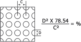
Figure 8. Standard design of micro perforation.
Download figure:
Standard image High-resolution image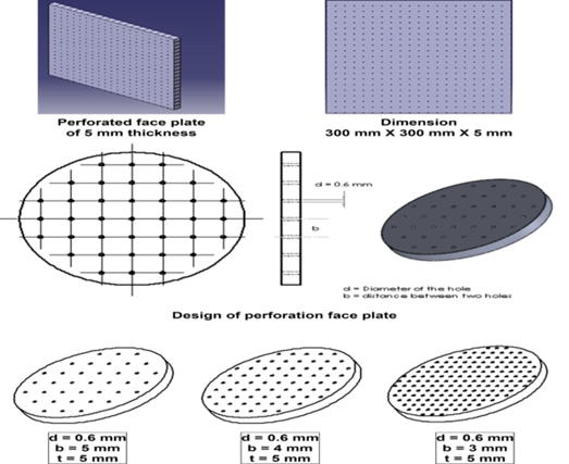
Figure 9. Design of micro perforation on PTGE based composites.
Download figure:
Standard image High-resolution imageTable 3. Micro perforation and distance between hole to hole on the face sheet.
| Sample ID | Micro perforation (one/two face sheet) | Distance between hole to hole (b) | Perforation ratio |
|---|---|---|---|
| Diameter of micro perforation (d) = 0.06 mm | |||
| Thickness of the face sheet (t) = 5 mm | |||
| (1/2) | mm | % | |
| C15-A1 | 1 | 3 | 3.142 |
| C15-A2 | 1 | 4 | 1.767 |
| C15-A3 | 1 | 5 | 1.131 |
| C15-B1 | 2 | 3 | 3.142 |
| C15-B2 | 2 | 4 | 1.767 |
| C15-B3 | 2 | 5 | 1.131 |
The sound absorption coefficients (SACs) for six distinct samples of microperforated PTGE-based NFRHCs were measured at varied frequency ranges using a small tube with a diameter of 29.5 mm and a bigger tube with a diameter of 99.5 mm, as illustrated in figure 10.
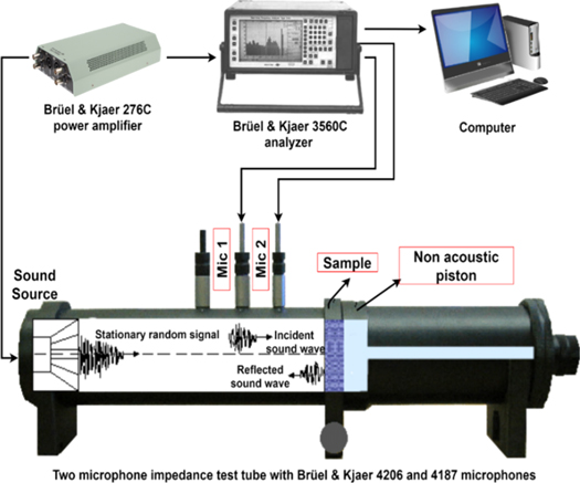
Figure 10. Testing process of PTGE based microperforated SCSP.
Download figure:
Standard image High-resolution imageResult and discussion
Sound absorption properties of PTGE based SCSP
In the frequency range 2000 Hz, the corrugated C-15 sample had a maximum SAC of 0.823 in the frequency range of 2000–6300 Hz was tabulated in table 4. Furthermore, the highest NRC was obtained to be 0.64. The NRC of the corrugated sandwich structure of total thickness 15 mm was found to be increased by 53.12% and 18.75%, compared to the flat structures of 5 mm and 15 mm thickness respectively. The figure 11 depicts the sound absorption curves of PTGE based SCSP.
Table 4. SACavg and NRC of PTGE based SCSP.
| Sample | Weight fraction of T-WTLF | SACavg | NRC | % Increase when compared to 15 mm flat structure |
|---|---|---|---|---|
| C15 | 25% | 0.617 | 0.64 | 18.75% |
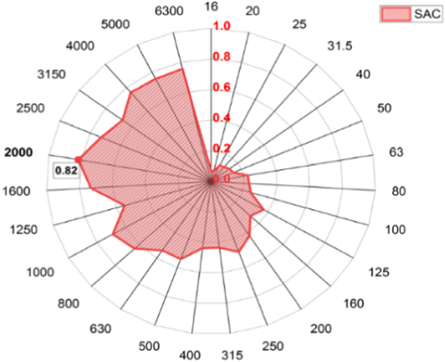
Figure 11. Sound absorption curve of PTGE based SCSP.
Download figure:
Standard image High-resolution imageSound absorption properties of PTGE based micro perforated SCSP
By ASTM E1050-10, the two-microphone impedance test tube method was used for determining the sound absorption properties of PTGE based micro perforated SCSP samples. The small tube setup with a diameter of 29.5 mm and the larger tube setup with a diameter of 99.5 mm calculate the sound parameter in the frequency range of 63 Hz to 6300 Hz. Table 5 shows the SACavg and NRC of PTGE based micro perforated SCSP sound absorption samples. The comparison between the all the micro perforated samples is depicted in figure 12.
Table 5. SACavg and NRC of PTGE based micro perforated SCSP.
| Sample | SACavg | NRC |
|---|---|---|
| C15-A1 | 0.638 | 0.65 |
| C15-A2 | 0.663 | 0.67 |
| C15-A3 | 0.683 | 0.69 |
| C15-B1 | 0.657 | 0.66 |
| C15-B2 | 0.685 | 0.69 |
| C15-B3 | 0.707 | 0.72 |
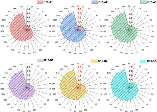
Figure 12. Sound absorption curves of PTGE based micro perforated SCSP without air gap.
Download figure:
Standard image High-resolution imageEffect of perforation ratio on sound absorption properties
The effect of the perforation ratio on the SACavg and NRC of six combinations without an air gap on the SCSP are investigated. From the table 4, it is observed that sample C15-B3 exhibited better SACavg and NRC than other micro perforated PTGE based SCSP. The micro perforation of 0.6 mm with distance between hole to hole as 5 mm showed better absorption of incident sound waves. Increased perforation ratio reduces the sound absorption properties. At lower frequencies, a lower perforation ratio results in a higher SACavg and NRC. To achieve the desired peak acoustic absorption frequency and a wider frequency range, the perforation ratio of the micro perforation layer must be adjusted in accordance with an appropriate sinusoidal core layer. Also, the addition of air gap with rigid backing still increases the SACavg and NRC of the PTGE based SCSP.
Effect of air gap and perforation ratio on sound absorption properties
The effect of the air gap and perforation ratio on the SACavg and NRC of six combinations on the SCSP are investigated as depicted in figures 13(a) and (b). The effect of air gap of 10, 20 and 30 mm on the sound absorption properties for the one side perforation (C15-A1, C15-A2 and C15-A3) and two side perforations (C15-B1, C15-B2 and C15-B3) is tabulated in table 6. The result showed that, the C15-B3 with 30 mm air gap exhibited the maximum SACavg and NRC as depicted in figure 14.
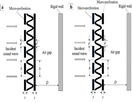
Figure 13. Schematic diagram of micro perforated PTGE based SCSP backed by a rigid wall with air gap in between (a) One-sided perforation (b) Two-sided perforation.
Download figure:
Standard image High-resolution imageTable 6. SACs and NRC of microperforated PTGE based SCSP with various air gap thickness.
| Compositions | Air gap | |||
|---|---|---|---|---|
| No air gap | With 10 mm air gap (D = 10mm) | With 20 mm air gap (D = 20 mm) | With 30 mm air gap (D = 30 mm) | |
| C15-A1 | ||||
| SACavg | 0.638 | 0.642 | 0.648 | 0.663 |
| NRC | 0.645 | 0.649 | 0.655 | 0.670 |
| C15-A2 | ||||
| SACavg | 0.663 | 0.667 | 0.673 | 0.689 |
| NRC | 0.670 | 0.674 | 0.680 | 0.696 |
| C15-A3 | ||||
| SACavg | 0.683 | 0.687 | 0.694 | 0.710 |
| NRC | 0.693 | 0.696 | 0.703 | 0.719 |
| C15-B1 | ||||
| SACavg | 0.657 | 0.660 | 0.667 | 0.682 |
| NRC | 0.660 | 0.664 | 0.670 | 0.685 |
| C15-B2 | ||||
| SACavg | 0.685 | 0.689 | 0.695 | 0.711 |
| NRC | 0.688 | 0.691 | 0.698 | 0.714 |
| C15-B3 | ||||
| SACavg | 0.707 | 0.711 | 0.717 | 0.734 |
| NRC | 0.718 | 0.722 | 0.728 | 0.745 |

Figure 14. Sound absorption curves of PTGE based micro perforated SCSP with air gap.
Download figure:
Standard image High-resolution image
By incorporating an air cavity behind the samples, the maximum SACavg and NRC values with a lower frequency range are increased. It was found that introducing an air gap significantly increased the absorption coefficient and absorption bandwidth in the low frequency region [13].
It was observed that when the air gap was increased by 10 mm, the sound absorption coefficient also increased, but reached a maximum at 30 mm air gap. This is because the air gap behind the sample is capable of absorbing the sound energy of longer wavelengths at medium and low frequencies. Therefore, the sound energy at long wavelengths (low frequency) can be absorbed by increasing the air gap. Similar results are obtained by increasing the material's thickness, which can improve the sound absorption coefficients at low, middle, and high frequencies due to an increase in sound energy losses. As observed in other studies [28], for achieving higher sound absorption coefficients at low frequencies by using a thicker material, it can simply be altered by incorporating an air gap, thereby reducing the number of fibers required. Consequently, this investigation has once again proved that if the material's thickness increases with an increase in airgap, the sound absorption coefficient increases.
Conclusion
All the aforementioned observations led to the conclusion that of 25% by weight of T-WTLF, 5% by weight of T-PALF, and 10% by weight of glass fibers with 60% by weight of epoxy resin on the corrugated sandwich and micro-perforated face sheets had a stronger effect on the SACavg and NRC without an air gap. Moreover, the trend towards micro-perforation increases for double-sided face sheets with a 30 mm air gap because of their lowest perforation ratio. It was demonstrated that increasing the air gap between the sample and the rigid wall is an effective method for enhancing sound absorption capabilities as well. By inserting an air cavity behind the samples, the greatest value of SAC is reached in the lower frequency band, as observed. In a similar way, the results illustrated that as the air cavity depth increase, the maximum value of SAC is reached at lower frequencies. This means that instead of increasing the thickness of the absorber, which consumes more fibers, an air gap can be employed to improve absorption at lower frequencies. This provides acousticians and architects with a wider range of alternatives for selecting the most effective sound-absorbing materials. Maximum absorption occurs at the resonance frequency corresponding to a quarter wavelength of the introduced air gap for a panel with a thickness much less than the air gap (thin sheet or membrane). This effect was more evident in the current investigation with thinner samples, i.e., samples with a thickness of 15 mm, where the SACs and NRC were lower and improved significantly when the air gap increased from 0 to 30 mm with micro perforation.
Acknowledgments
I (Karthi N), thank all the co-authors for their expertise and assistance throughout all aspects of our study and for their help in writing the manuscript.
Data availability statement
The data generated and/or analysed during the current study are not publicly available for legal/ethical reasons but are available from the corresponding author on reasonable request.
Conflict of interest
The authors declare that there are no conflicts of interest regarding the publication of this article.