
Abstract
In this study, the effectiveness of a Lambertian back reflector for trapping light in a MAPbI3 perovskite solar cellhas been investigated. The propagation of collimated and diffuse light in the cell has been modelled using the transfer-matrix method and the radiative transfer equation respectively. We show that in the presence of such a reflector, the population of tail states at wavelengths beyond the band-edge of a conventional cell can be substantially increased. As a result of this enhanced light absorption, the power conversion efficiency of a 600 nm thick active layer in a conventional n-i-p (p-i-n) cell is shown to be attainable with a reduced thickness of 300 nm (200 nm) in the presence of light trapping. The effect of photon recycling to increase the open circuit voltage in these structures has also been studied for different thicknesses of the active layer. An increased open circuit voltage in the range 125–145 mV is observed for a Lambertian back reflector as compared to 155–170 mV increase seen in a conventional cell with metallic back reflector.
Export citation and abstract BibTeX RIS

Original content from this work may be used under the terms of the Creative Commons Attribution 4.0 licence. Any further distribution of this work must maintain attribution to the author(s) and the title of the work, journal citation and DOI.
1. Introduction
Perovskite solar cells (PSCs) have a great scope to serve as future energy harvesting devices [1, 2] on account of these third-generation thin film solar cells exhibiting multifaceted advantages compared to first- and second-generation cells such as ease of processing, tunability of band gap, low average cost per unit area, and readily available base precursors [3]. The major challenge still to be addressed is their large area production and instability when exposed to light, heat, and moisture due to which PSCs lag behind silicon solar cells for commercial applications [4–6]. The power conversion efficiency of PSCs has steadily increased from 3% to 24% over the last decade and current research aims to limit their degradation while retaining their optoelectronic properties and explore means to scale up for commercialization [1, 7]. The relevant properties that aid their enhanced electrical properties are their long carrier diffusion length, high light absorption coefficient, high charge carrier mobility and band structure tunability [8].
In general, thin film PSCs with an average absorber layer thickness ranging 0.5 to 1 μm show superior open circuit voltage (Voc), short circuit current density (Jsc) and high efficiency (η) [9]. Studies on ultrathin PSCs with absorber layer thickness less than 0.5 μm are also of importance due to their utility in standalone applications such as wearable or portable electronics, unmanned aircrafts, and building-integrated photovoltaics [10, 11]. The decrease in absorber thickness provides additional advantages such as minimized recombination rate and reduction in use of toxic materials when PSCs are scaled up for production. However, this reduction in absorber thickness in conventional PSCs comes at the expense of reduced optical path length resulting in insufficient light absorption - particularly for the longer wavelengths in the VIS-NIR range. Therefore, to keep the optical path length intact with decreasing thickness, one needs to take advantage of light trapping approaches. These light trapping techniques help increase the coupling of sunlight to the absorber layer and thus increase the optical path length [12]. This not only enables the use of thinner absorber layers but also enhances the broadband absorption into the NIR region [13–15].
Different light trapping approaches have been proposed in the last few years for PSCs, such as textured front and rear surfaces [16], fibre array based anti-reflection front electrodes [12], UV downshifting and light trapping [17], nanophotonic front and back electrodes [18], design of nano prism structures at perovskite-CIGS interface [19], utilization of Lambertian back reflector (LBR) [20], as well as exploitation of carbon dot-wrapped perovskites [21]. Among these, of particular importance is the utility of LBR in light trapping vis-à-vis texturing of surfaces. Although the random texturing of perovskite at its interfaces with ETL or HTL potentially increases light absorption, major drawbacks with this process include difficulty in fabrication involved [22], and the reduction in crystallinity of the perovskite films resulting in a large number of grain boundaries [23]. This causes enhanced trap-assisted recombination due to deep level defects at the grain boundaries and interfaces deteriorating the device performance. The use of white paint as LBR not only provides a cheaper alternative but also involves no texturing at the interface of absorber, front and back layer contact thereby minimizing the effect on charge extraction. White paint that reflects >95% of sunlight is available commercially and can serve as an effective LBR [24–26]. Thus, light trapping technique with white paint as LBR can not only be utilized to increase light absorption but also avoid degradation of the interfaces.
In this study we explore the utility of LBR in PSCs for enhancement in light absorption and thereby its photovoltaic parameters in both regular (n-i-p) and inverted (p-i-n) architectures. The performance is compared with that of a standard PSC configuration with metallic back reflector (MBR). Similar studies [27, 28] have explored the use of LBR in MAPbI3 PSCs in the standard n-i-p configuration combining Monte-Carlo technique and transfer-matrix method to model the diffuse and coherent light propagation respectively. We extend these works to explore optimization in both n-i-p and p-i-n (inverted) structures, and also study the effect of photon recycling in these cells. In particular we show that the p-i-n structure gives superior performance in the presence of Lambertian scattering. Our model also differs in that we use discrete-ordinate method with double Gaussian quadrature [29] in conjunction with the transfer-matrix method [30] to model both the propagation of diffuse flux as well as account for interference effects in the collimated part of light propagation in the solar cell. This method has been previously [31, 32] used to demonstrate the possibility of attaining increased Jsc using LBR in thin CIGS films. However, while the change in efficiency due to increased optical absorption was quantified for thin CIGS films, the effect on recombination rate was not considered. In this work we seek to quantify the enhancement in Jsc (and hence the efficiency of PSCs) due to both increased optical absorption as well as reduced recombination rate due to the use of LBR in PSCs. We also include an analysis on the effect of photon recycling, since recent studies [33, 34] have shown that the effect of photon recycling in enhancing the open circuit voltage Voc in cells with MBR is far more effective than those with LBR. Since both Jsc and Voc affect the final power conversion efficiency of the cell it will be important to quantify the net resulting efficiency due to the contrasting impacts of substituting MBR with a LBR on the parameters Jsc and Voc.
2. Methodology for simulation and device architecture
In this study, the absorption spectra with different active layer thickness are modelled with the following assumptions:
- (i)The interfaces of all layers are considered as perfectly smooth so that Fresnel reflection and transmission of light can be assumed at the interfaces.
- (ii)The scattered light from LBR is the only source of diffuse light, as shown in figure 1.
In this model, our interest is to calculate the fraction of total incident light absorbed in MAPbI3 (active) layer. For unpolarized light incident on the solar cell at an angle θ, this fraction is the sum of the coherent and diffuse components and is given by:

where  is the fraction of coherent light of polarization pi (i = TE, TM) absorbed in the active layer calculated as:

Here,  is the time-averaged z-component of the Poynting vector of the incident light, with
  (
( ) being the electric (magnetic) field of the incident radiation and '*' denoting the complex conjugate.
  and
and  are the similarly defined time-averaged z-components of the Poynting vector calculated at the two interfaces of the MAPbI3 layer, with the required electric and magnetic fields being obtained using the transfer-matrix method [30]. Scattering at the LBR converts the coherent, collimated light to diffuse whose propagation in the multi-layered cell is modelled using the radiative transfer equation. In particular, we adopt the discrete ordinate method with double Gaussian quadrature [29] to quantify the diffuse intensities in different directions at all the interfaces in the cell. The fraction of incident light that is absorbed in the MAPbI3 layer as diffuse light
  is then calculated as:

Here 'μ' is the direction cosine of rays of the diffuse light in the MAPbI3 layer, I(1) and I(2) are the specific intensities at the two interfaces of the MAPbI3 respectively. For a more detailed discussion regarding this model, the code for which was written in Matlab [35], the reader is referred to [31].
For the present study, optical absorption spectra are extracted for both n-i-p and p-i-n structures and compared for the case when MBR is replaced with a LBR. We consider the case of normal incidence (θ = 0°) in this work. The configuration of the solar cell is shown in figure 1. We have taken TiO2 (50 nm) for electron transport material, NiO (50 nm) for hole transport layer, MAPbI3 as absorber with varying thickness, ITO (100 nm) as transparent front electrode, and silver as MBR. The refractive index data of MAPbI3(figure S1 in supplementary information) is taken from [36] and that for other layers, including that of MBR, from [37]. We have simulated the performance of this configuration for two cases (i) with silver as MBR and (ii) with white paint as LBR considering 99% reflectance consistent with properties of some of the commercial white paints available [38]. To enable diffuse reflectance from LBR while also being able to extract charges from solar cell we propose that finger electrodes be deposited on the hole/electron transport layer with the white paint filling the gap between the fingers as shown in figures 2(a) and 1(b).
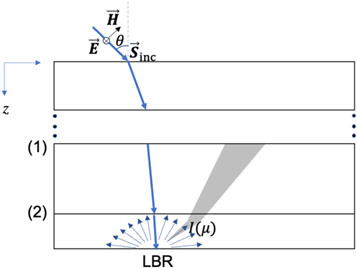
Figure 1. Representative figure showing incident TE-polarized coherent collimated radiation (shown in blue), its transmission in the multi-layered structure, and its conversion to diffuse radiation (shown in grey) at the LBR interface. Reflected beams at interfaces are omitted.
Download figure:
Standard image High-resolution image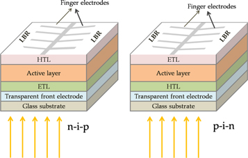
Figure 2. Proposed device configuration considered for the present work (n-i-p and p-i-n structures). Top view of the rear side with LBR along with the finger electrode pattern to be deposited on the HTL and ETL respectively.
Download figure:
Standard image High-resolution imageThe performance characteristics of the PSC are calculated using the absorption coefficient from equation (1). The standard expressions used for the calculations of these characteristics have been reproduced below for the sake of completeness. In this work, only radiative recombination is considered and the contribution of non-radiative recombination due to defects has been ignored. The total current density considering the generation and recombination current is given by [39].

where Qs (with units of m−2s−1) is the photon flux being absorbed in the active layer of the solar cell and calculated as:

with  being the non-dimensional absorption coefficient from equation (1),
  (with units of m−2.eV−1.s−1) being the incident photon flux as a function of photon energy which is calculated recognizing that
  and,
and,  being related to the spectral irradiance Irr (λ) on the cell (units of W m−2 nm−1) taken to be AM1.5 G spectra [40].

'h' being the Planck's constant, and 'c' being speed of light in vacuum. The recombination rate RR (unit of m−2 s−1) in equation (4) is calculated as [40]:

with kB being the Boltzmann factor, T the temperature of the cell, and Qc(units of m−2s−1) being calculated using [40]:

Substituting equations (5) and (7) in equation (4) gives us the J-V characteristics of the cell from which the short circuit current density (Jsc) and the open circuit voltage (Voc) can be obtained. Under short circuit condition with V = 0, Jsc is obtained as:

and under open circuit condition with J = 0, Voc is obtained as:

The fill-factor FF(in %) of the solar cell is calculated using:

and the power conversion efficiency η (in %) from:

where Pin is the irradiance equal to 100.301 mW cm−2.
3. Results and discussion
3.1. Absorption spectra for the n-i-p and p-i-n configurations
Absorption spectra for n-i-p MaPbI3 thin film configuration with active layer thickness 300 nm and 600 nm for the two cases when MBR and LBR are included are shown in figure 3(a), and similarly for the p-i-n configuration for active layer thicknesses 200 nm and 600 nm are shown in figure 3(b). Data for other thicknesses ranging from 100 to 600 nm for the n-i-p and p-i-n configurations are provided in supplementary information (Fig S2).
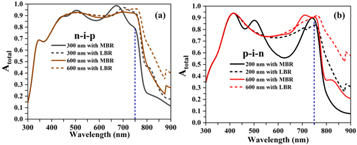
Figure 3. Comparison of absorption spectra of MAPbI3 thin film solar cell for (a) conventional (n-i-p) and (b) inverted (p-i-n) architectures. Dotted blue line at 750 nm wavelength marks the band edge typically considered for conventional MAPbI3 cells.
Download figure:
Standard image High-resolution imageBand-edge of polycrystalline MAPbI3 perovskite material lies close to 750 nm wavelength [41] due to which light absorption is generally taken to be negligible beyond this wavelength in conventional cells with MBR. This edge is marked by a sharp fall in the imaginary part of refractive index (see figure S1 in supplementary) and hence also in Atotal as observed in figures 3(a) and (b) for cells with MBR. However, in the presence of LBR, we note a significant red shift in absorption beyond this band-edge of MAPbI3.This increase in population of tail-states in NIR region in the presence of LBR is due to diffuse reflectance of light back into the absorber allowing an increase in the optical path length and thereby enhancing the light absorption despite small imaginary part of refractive index  at such wavelengths (see figure S1 in supplementary).To take into account this enhanced absorption in tail-states, Qs from equation (5) and Qc from equation (8) are calculated over the wavelength range 300–900 nm. We neglect any light absorption beyond 900 nm wavelength since absorption at such wavelengths are primarily due to defect states, and an accurate quantification of solar parameters cannot ignore nonradiative recombination effects resulting from the presence of these material defects. Such a consideration is beyond the scope of the present theoretical work. The increased absorption in NIR region is important to increase Jsc since Sunlight has a significant portion of energy in this wavelength range. Similar effect is seen in thin single-crystal perovskite solar cells where lack of defects results in a significant red-shift up to 820 nm thereby increasing the efficiency compared to polycrystalline cells [41, 42]. From figure 3(b) a larger shift towards NIR is noticed for p-i-n compared to n-i-p in the presence of LBR. This enhancement in absorption is due to lower refractive index contrast at the TiO2/MAPbI3 interface for p-i-n configuration compared to the NiO/MAPbI3 interface for n-i-p configuration which results in a larger span of refraction scattering angles in the MAPbI3 layer for the p-i-n configuration as shown in figure 4.

Figure 4 : Comparison between the span of scattered light angles in the n-i-p and p-i-n configurations in the presence of LBR. The values of real part of refractive indices for the layers at  wavelength are indicated.
Download figure:
Standard image High-resolution imageThe values of weighted average absorption coefficient (WAA) calculated over the 300–900 nm wavelength range as:  are presented in table 1. Corresponding values for other thicknesses of MAPbI3 layer are shown in the supplementary file (Table S1).
Table 1. Calculated weighted average absorption coefficient (WAA) for n-i-p and p-i-n architectures.
| Thickness of MAPbI3 | WAA for n-i-p | Thickness of MAPbI3 | WAA for p-i-n | ||
|---|---|---|---|---|---|
| 300 nm | With MBR | 64.5 | 200 nm | With MBR | 56.2 |
| 300 nm | With LBR | 70.9 | 200 nm | With LBR | 66.6 |
| 600 nm | With MBR | 70.5 | 600 nm | With MBR | 65.7 |
| 600 nm | With LBR | 76.8 | 600 nm | With LBR | 75.9 |
Remarkably, it is seen that for the n-i-p configuration the absorption coefficient for active layer thickness 300 nm in the presence of LBR is comparable to that for active layer thickness 600 nm in the presence of MBR (the comparable values are underlined). For the p-i-n configuration, the absorption coefficient for active layer thickness 200 nm in the presence of LBR is seen to be comparable to that for active layer thickness 600 nm in the presence of MBR. While the possibility of two-fold reduction in thickness of active layer with the use of LBR in place of MBR in n-i-p configuration has been reported previously [28], to the best of knowledge of authors the more profound three-fold possible decrease in thickness of active layer for the p-i-n configuration has not been reported. It is worth reiterating that this enhanced absorption seen in the case of p-i-n configuration is due to the larger light scattering angles for the diffuse scattered light in the active layer compared to that seen in n-i-p configuration. This approach has been previously exploited to increase light absorption in thin-film CIGS cells [32].
3.2. Solar parameters
In order to effectively evaluate and analyze the performance of PSCs with MBR and LBR as back reflectors, the values of Jsc, Voc, FF and η are calculated using equations (10) to (13). These values are plotted in figures 5 and 6 for the n-i-p and p-i-n configurations respectively.
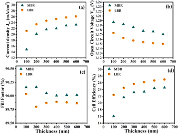
Figure 5. Comparison of thickness dependent (a) Jsc (b) Voc (c) FF and (d) η for n-i-p configuration in the presence of MBR and LBR.
Download figure:
Standard image High-resolution image
Figure 6. Comparison of thickness dependent (a) Jsc (b) Voc (c) FF; and (d) η for p-i-n configuration in the presence of MBR and LBR.
Download figure:
Standard image High-resolution image3.2.1. For regular structure (n-i-p)
It can be inferred from figure 5(a) that Jsc increases from 16.81 to 25.55 mA cm−2 as the thickness is increased from 100 to 600 nm in the presence of MBR, whereas in the presence of LBR, the corresponding increase is from 21.17 to 27.29 mA cm−2. A general trend of increasing Jsc with thickness is observed due to the absorption of more photons resulting in generation of more electron hole pairs. With LBR, the enhancement of Jsc can be attributed to the increased absorption in the NIR wavelengths as was shown in figure 3. In figure 5(b) the solar parameter Voc is plotted as a function of thickness. A downward trend with increasing thickness is observed due to increased dark saturation current Qc, which increases the possibility of recombination of electron-hole pairs [43]. Higher radiative recombination in the presence of LBR due to the diffuse scattering of light in all directions results in lower values of Voc compared to the configuration with MBR. Fill factor (FF) values plotted in figure 5(c) are similar for both MBR and LBR configurations with negligible decrease observed with increasing thickness for both these cases. This is primarily because non-radiative recombination in the active layer is not considered in the present study which is known to affect FF substantially [44]. The plot of PCE (η) as a function of thickness shown in figure 5(d) is found to have an increasing trend for cells with LBR and MBR, similar to the trend observed for Jsc, and which can be attributed primarily to the increased light absorption. From figure 5(d) it can also be noted that a PCE value with active layer thickness 600 nm in the presence of MBR (27.09%) can be obtained at a reduced active layer thickness of 300 nm in the presence of LBR (26.93%).
3.2.2. For inverted structure (p-i-n)
The plot of cell parameters Jsc, Voc, FF, and PCE as a function of thickness for the p-i-n structure with MBR and LBR are shown in figures 6(a)–(d) respectively. Trends observed are similar to that observed for n-i-p structure and can be attributed to similar factors. From figure 6(d)it should be noted that the cell efficiency for a 200 nm thick active layer (24.46%) in the presence of LBR is comparable to that of a 600 nm thick active layer (23.20%) in the presence of MBR. This possibility of threefold decrease in thickness which can be attained while retaining the same PCE is noteworthy.
3.3. Effect of photon recycling
The expression used for calculating Voc in equation (10) implicitly includes the effect of photon recycling [33]. That is, the photons emitted due to radiative recombination are assumed to get re-absorbed and further create electron-hole pairs thereby increasing the voltage, compared to the case where they are emitted from the cell without re-absorption. This increase in voltage has been the focus of several recent studies [33, 34, 45] since the increase in voltage via photon recycling has been shown to be substantial thereby being a major factor for increased PCE in these cells. While we have so far neglected the effect of non-radiative recombination in this work, we can nonetheless quantify the reduction in Voc relevant for situations when photon recycling becomes minimal (such as due to predominance of nonradiative recombination effects). The difference in Voc with and without the presence of photon recycling is given by [33]:

Here α is the absorption coefficient of the active layer related to the imaginary part of the refractive index, k, as  't' is the thickness of the active perovskite layer, and 'n' is the real part of the refractive index of the active layer.
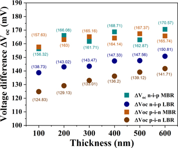
Figure 7 shows the plot of ΔVoc as a function of thickness of the active layer for the n-i-p and p-i-n configurations. Observed ΔVoc values in the presence of MBR is higher (in the range 155–170 mV) compared to that in the presence of LBR (in the range 125–145 mV). The higher ΔVoc values in the presence of LBR has been previously reported in literature [33] and has been attributed to photons having fewer chances to couple out of the cell from the front end in the presence of MBR as compared to LBR [46].
Figure 7. Calculated values of ΔVoc for n-i-p and p-i-n configurations with MBR and LBR considering photon recycling.
Download figure:
Standard image High-resolution image
In conclusion, solar parameters for conventional MAPbI3 based n-i-p and p-i-n perovskite cells have been calculated and compared for the case when the MBR is substituted with a LBR. The results reveal that the efficiency of conventional perovskite cells can be reproduced at much lower values of active layer thickness for both n-i-p and p-i-n structures when a LBR is used. In particular, it is observed that the PCE for a conventional n-i-p (p-i-n) configuration cell with 600 nm thick active layer can be achieved using a decreased active layer thickness of 300 nm (200 nm) in the presence of a LBR. This enhancement in efficiency observed for the p-i-n configuration vis-à-vis then-i-p configuration has been shown to be due to the added advantage of lower refractive index contrast at TiO2/MaPbI3 interface in the former compared to that at NiO/MaPbI3 interface in the latter leading to enhanced light trapping.
Acknowledgments
The authors thank Jean-Jacques Greffet for making available the code to calculate the light absorption in a multi-layer cell in the presence of diffuse scattering. K S set up the problem; A T and S A carried out the simulations; K S and A T analysed the results; A T and K S wrote the manuscript.
Data availability statement
The data that support the findings of this study are available upon reasonable request from the authors.