
Abstract
In order to improve the quality of pulsed laser welding on magnesium alloy, the effect of pulse overlap rate on the microstructure and mechanical properties of the welds is studied. A Nd:YAG pulsed laser welding machine is used to carry the butt welding experiments on AZ31 magnesium alloy (1 mm), and the pulse overlap rate (10%, 30%, 50%, 70%, 90%) is varied by adjusting the welding velocity. The experimental results show that with the increases of pulse overlap rate, the sensitivity of the solidification cracks and pores decreases. The grain size of the columnar grains at the fusion boundary (FB) and the equiaxed grains in the center of the welds increases and then decreases and reach the maximum value of 114.72 ± 3.06 μm and 74.08 ± 5.87 μm, respectively, when the overlap rate is 70%. The percentage of the ductile fracture in the fracture of tensile specimens is proportional to the pulse overlap rate. With the increases of the pulse overlap rate, the tensile strength and maximum force show a trend of decreasing first and then increasing, and both reach the maximum value of 94.583 MPa and 1.135 kN when the overlap rate is 90%. Besides, the microhardnesses of the welds decrease first and then increase, and it's maximum value is 86 HV0.2. In summary, the welds with better surface morphology can be obtained at the pulse overlap rate of 70%, while the mechanical properties of the welds are better when the overlap rate is 90%.
Export citation and abstract BibTeX RIS

Original content from this work may be used under the terms of the Creative Commons Attribution 4.0 licence. Any further distribution of this work must maintain attribution to the author(s) and the title of the work, journal citation and DOI.
1. Introduction
Magnesium alloys are characterized by the low density, high specific strength, easy recycling and high corrosion resistance, and have broad application prospects in the shell of mobile phones and notebook computers, aerospace, microelectronics and other fields. With the development of computer, communication and consumer electronics, the magnesium alloy sheet has been used widely [1, 2]. Pulsed laser welding has the advantages of the small heat input, high precision and high degree of automation, which can improve the production efficiency and reduce the heat affected zone, especially suitable for sheet magnesium alloy welding [3, 4]. However, due to the low melting point, high linear expansion coefficient and strong affinity with oxygen of magnesium alloys, the cooling rate of the molten pool of thin-plate magnesium alloys (≤1 mm) in laser welding is extremely fast, and defects such as cracks, pores and inclusions are prone to occur after welding, which has a great impact on the mechanical properties of welded joints [5].
A 2 kW continuous fiber laser is used by Chowdhury et al [6] on 2 mm AZ31B-H24 magnesium alloy to study the effect of welding velocity on the welding microstructure and mechanical properties, and the experimental results show that the higher the welding velocity, the greater the yield strength and the longer the fatigue life. Gao et al [7] conduct welding experiments on ZK60 magnesium alloy of 2 mm by using a 3 kW continuous fiber laser, and study the influence of welding velocity on the microstructure. The experimental results show that with the welding velocity increases, the welding width and the grain size decreases. Chen et al [8] carry out welding experiments on AZ61 magnesium alloy of 2 mm by using a 3 kW continuous CO2 laser, and study the effects of grain size and precipitation on the liquation cracking. The results show that the larger the grain size, the more precipitates with low melting point, and the more serious the liquation cracking. A continuous CO2 laser is used by Yu et al [9] to conduct welding experiments on 10 mm ZK60 magnesium alloy to study the effect of process parameters on the cracking tendency. The results show that with the increase of welding velocity, the sensitivity of the cracks increases, and the form of weld cracking changes from transverse to longitudinal. The effect of welding parameters on weld porosity and overfill is investigated by Pastor et al [10] using a 3 kW continuous Nd:YAG laser to weld 2 mm and 6 mm AM60B magnesium alloy, respectively. The experimental results show that the porosity in the weld is mainly formed by the expansion and aggregation of the original porosity in the base metal (BM), besides, the displacement of liquid metal on the melt surface and the pores will cause the overfill. The number of the big pores can be reduced by decreasing the heat input. The above researches indicate that most of the current researches on laser welding of magnesium alloy focus on continuous laser welding of BM with the thickness greater than 2 mm. There are few studies on pulsed laser welding of thin magnesium alloy with the thickness less than 1 mm, especially on improving the surface morphology and mechanical properties of the welds. Therefore, it is necessary to develop the technical means to improve the surface morphology and mechanical properties of magnesium alloy by the pulsed laser welding.
Therefore, in order to expand the application and theoretical research of magnesium alloy in the field of electronic products, this paper used AC-300W pulsed laser to conduct the butt welding experiments on 1 mm AZ31 magnesium alloy sheets to study the effect of pulse overlap rates on the microstructure and mechanical properties of laser welds of thin magnesium alloy sheet. By adjusting the welding velocity, the overlap rate of weld (10%, 30%, 50%, 70%, 90%) can be varied to improve the surface morphology and mechanical properties of the welds. In order to explore the effect of pulse overlap rate on the weld microstructure, welding defects and mechanical properties, and determine the optimal pulse overlap rate to obtain excellent welds, stereoscopic microscopy, metallographic microscopy, and scanning electron microscopy are used in this paper. This study provides a research basis for exploring the effect of pulse overlap rate on the weld microstructure, welding defects and mechanical properties of the thin-plate magnesium alloys by pulsed laser welding.
2. Experiment
AZ31 magnesium alloy of 50 mm×50 mm×1 mm with the composition shown in table 1 is chosen as the BM. The AC-300W YAG pulsed laser welding machine is selected for the butt welding of magnesium alloy sheets, and its main technical parameters are shown in table 2. The welding process of the pulsed laser is shown in figure 1.
Table 1. Composition of AZ31 magnesium alloy for experiment (wt%).
| Al | Zn | Si | Fe | Cu | Mn | Ni | Mg |
|---|---|---|---|---|---|---|---|
| 2.90 | 0.837 | 0.067 | 0.0045 | 0.005 | 0.431 | 0.0013 | Balance |
Table 2. Main technical parameters of experimental pulsed laser.
| Technical parameter | Numerical value |
|---|---|
| Laser working medium | Nd+3:YAG |
| Wavelength | 1.064 μm |
| Pulse time | 0.1 ∼ 15 ms |
| Pulse peak power | 1 ∼ 9.9 kW |
| Focal radius | 0.25 mm |
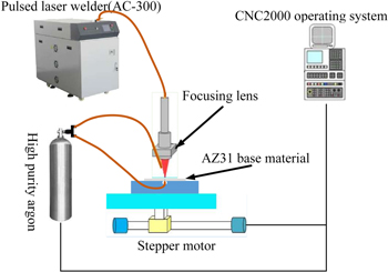
Figure 1. Schematic diagram of pulsed laser welding process.
Download figure:
Standard image High-resolution imageBefore the experiment, the surface of the BM is sanded with 600 #SiC sandpaper to remove the oxide layer and the acetone solution is used to wipe off the grease on the surface of specimens. The experimental parameters of the pulsed laser welding are shown in table 3. The pulse overlap rates are varied by adjusting the welding velocity, and their relationship is as follows:

Where, Of is the overlap rate of upper surface welds, V is the welding velocity, f is the pulse frequency, t is the pulse time, D is the bead width.
Table 3. Experimental parameters of pulsed laser welding.
| Peak power/kW | Pulse time/ms | Pulse frequency/Hz | Defocus amount/mm | Flow rate of front shielding gas l−1·min−1 | Flow rate of back shielding gas l−1·min−1 | Welding overlap rate | Welding velocity/mm·min−1 |
|---|---|---|---|---|---|---|---|
| 4 | 5 | 15 | 0 | 10 | 5 | 10% | 810 |
| 4 | 5 | 15 | 0 | 10 | 5 | 30% | 630 |
| 4 | 5 | 15 | 0 | 10 | 5 | 50% | 450 |
| 4 | 5 | 15 | 0 | 10 | 5 | 70% | 270 |
| 4 | 5 | 15 | 0 | 10 | 5 | 90% | 90 |
After the welding experiment, the welding samples are cut transversely along the weld center according to the size of 8 mm × 20 mm × 1 mm. Then, the metallographic experiments such as inlay, polishing, ultrasonic cleaning, and etching are carried out. The composition ratio and application of the etchant are shown in table 4. The welding samples are made into the shape and size as shown in figure 2 for tensile experiments. Figure 3 shows the morphology of the tensile specimens. The microhardnesses of the welding cross-sections are measured by HVS-1000 microhardness tester with 25 g loading load and 10 s loading time. The microhardnesses are measured along perpendicular to the welds with 0.03 mm spacing. Besides, the hardnesses of the overlapping FB of the adjacent pulses are also measured as shown in figure 4.
Table 4. Composition ratio, etching time and application of etching agent for experiment.
| Corrosive agent | Component | Corrosion time | Purpose |
|---|---|---|---|
| 1# | Picric acid 4.2 g | 12 s∼14 s | Scanning electron |
| Absolute ethanol 70 ml | microscope | ||
| Acetic acid 10 ml | observation | ||
| Distilled water 10 ml | |||
| 2# | Nitric acid 4 ml | 10 s | Observation with stereomicroscope or metallographic microscope |
| Absolute ethanol 96 ml |
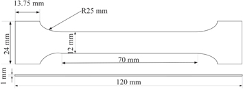
Figure 2. Shape and size of tensile specimens.
Download figure:
Standard image High-resolution image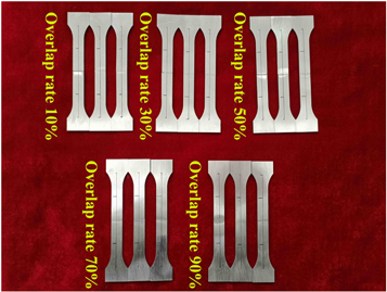
Figure 3. Laser welded tensile specimens at each overlap rate.
Download figure:
Standard image High-resolution image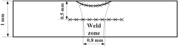
Figure 4. Microhardness measurement sampling point location.
Download figure:
Standard image High-resolution image3. Results and discussion
3.1. Macrostructure analysis
3.1.1. Weld morphology
Figure 5 shows the cross-sectional pictures of AZ31 magnesium alloy of pulsed laser welds at different overlap rates, and figure 6 shows the measured widths of the upper and lower of the welding surface. It can be seen from figures 5 and 6 that with the increase of the pulse overlap rates, the widths of the upper and lower surface increase from 1.30 mm and 0.25 mm to 1.93 mm and 0.96 mm respectively. This is because the pulse time and pulse frequency are unchanged, and the interaction time and number between the laser beam and the BM per unit time remain unchanged. The reduction of welding velocity increases the weld overlap rates, which increases the effective heat input from the laser beam to the BM, as shown in equation (2) [11]. Therefore, the welds with larger upper and lower surface widths can be obtained when the overlap rate is 70% and 90%. However, at this time, the peak temperature of the molten pool is so high that the melt metal is burned seriously.

Where, E is the heat input, P is the pulse peak power, t is the pulse time, V is the welding velocity, η is the thermal efficiency coefficient.
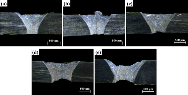
Figure 5. Cross-sectional images of pulsed laser welds of AZ31 magnesium alloy at different overlap rates: (a) Of = 10%; (b) Of = 30%; (c) Of = 50%; (d) Of = 70%; (e) Of = 90%.
Download figure:
Standard image High-resolution image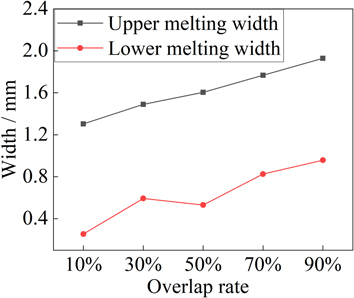
Figure 6. Influence of overlap rates on upper and lower widths of welds.
Download figure:
Standard image High-resolution image3.1.2. Weld defect
Figure 7 (welding cross-sections under the metallographic microscope) presents that there are mainly solidification cracks, pores and undercut defects in the welds. Figure 8 shows the effect of pulse overlap rates on the geometric size of the weld defects. It is clear that with the increase of the overlap rates, the length of solidification cracks and the pores area decrease, and the undercut depth increase from 0.063 mm to 0.323 mm. When the overlap rate is 90%, solidification cracks are not observed and the pore area reaches the minimum 0.001 mm2.
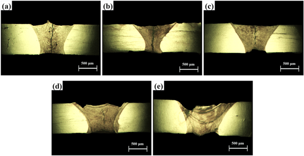
Figure 7. Images of the cross-sections of the welds with different pulse. overlap rates under metallographic microscope: (a) Of = 10%; (b) Of = 30%; (c) Of = 50%; (d) Of = 70%; (e) Of = 90%.
Download figure:
Standard image High-resolution image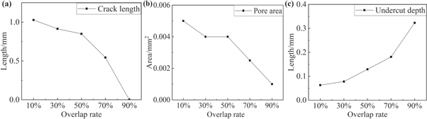
Figure 8. Effect of the overlap rates on the geometric dimensions of the weld defects: (a) Crack length; (b) Pore area; (c) Undercut depth.
Download figure:
Standard image High-resolution imageAccording to literature [12–16], AZ31 magnesium alloy is a typical eutectic alloy. The cooling rate of the molten pool of pulsed laser welding is fast, and the unbalanced crystallization is prone to occur, resulting in the formation of a 'liquid film' formed by the low melting point eutectic β-Mg17Al12 at the grain boundary. Moreover, the rapid heating and cooling of the welding zone greatly increases the tensile stress of the weld metal, and the tensile stress increases with the increases of the cooling rate. Therefore, solidification cracks are easy to occur at the grain boundary. As the overlap rate increases, the welding velocity decreases and the welding heat input per unit time increases. It will reduce the cooling rate of the molten pool, so as to reduce the tensile stress of the welds and weaken the unbalanced crystallization of the liquid metal. Therefore, the length of solidification cracks decreases.
According to literature [17, 18], hydrogen is the only gas that dissolves in liquid magnesium, which mainly comes from the oxide layer on the BM surface and the welding atmospherethe and the solubility of H2 in Mg decreases from 20 ml/100 g to 0 ml/100 g as the temperature decreases from 922.8 K to room temperature. During the pool solidification of the pulsed laser welding of magnesium alloy, the hydrogen dissolved in the pool escapes due to the decrease of solubility. Its escaping velocity is shown in the equation (3). When the molten pool is cooled, the temperature decreases, making the viscosity and density of the liquid magnesium alloy increase sharply (as shown in equation (4) and (5)), but the viscosity increases greatly[18]. Therefore, the escaping velocity of bubbles is reduced, and the possibility of bubbles remaining in the welds to form pores is increased. During the solidification process of molten pool, the solidification shrinkage of columnar crystal increases and the backfilling capacity of liquid decreases. When the shrinkage rate is greater than the liquid reflux rate and reaches the critical value, hydrogen atoms will be enriched and pores will be formed. As the overlap rate increases, the cooling rate decreases, the molten pool exists for longer and the peak temperature of the molten pool increases. Thus, the escaping time and veloctiy of bubble increases. As a result, the pores sensitivity decreases.

Where, v is the bubble escape velocity, g is the gravitational acceleration, ρ1 is the density of liquid magnesium alloy, ρ2 is the density of gas, r1 is the bubble radius.

Where, η is the viscosity of liquid metal, η0 and E is constants related to magnesium alloys, T is the temperature of molten pool, R is the gaseous constant.

Where, ρ is the density of liquid AZ31 magnesium alloy, ρm is the density of AZ31 magnesium alloy at melting temperature,  is the density-temperature-dependent coefficient of variation of AZ31 magnesium alloy, Tm is the melting point of AZ31 magnesium alloy.
In the welding pool, the liquid metal gathers near the FB of the BM surface flows towards the center of the pool under the action of Bouyancy convection caused by gravity and Marangoni convection caused by surface tension [19]. Due to the rapid cooling rate of the molten pool of pulsed laser welding during the solidification, liquid metal cannot be filled in time, so the undercut is formed at the position of FB. With the increases of the overlap rate, the peak temperature of the molten pool increases, which intensifies the fluid flow of the molten pool and increases the slip of the liquid metal at the FB, thereby increasing the undercut depth. Besides, higher peak temperature will aggravates the evaporation and burning loss of liquid metal in the molten pool, which would reduce the weld metal and further increase the undercut depth. In summary, the weld with a better surface topography can be obtained when the overlap rate is 70%.
3.2. Microstructure analysis
Figure 9 shows the micrographs near the FB of pulsed laser welds of AZ31 magnesium alloy at different overlap rates. It is discernible from figure 9 that the grains near the FB are mainly columnar crystals, which grow epitaxially along the direction perpendicular to the FB. Table 5 shows the grain size under different pulse overlap rates. The results show that with the increases of overlap rate, the grain size at the FB increases first and then decreases. The grain size reaches a maximum of 114.72 ± 3.06 μm at 70% overlap rate. This is because the semi-melted BM grains at the FB can be used as the nucleation matrix for columnar crystals, and the temperature gradient in the direction perpendicular to the FB is the largest. Thus, the columnar crystals grow epitaxially along the direction perpendicular to the FB. As the overlap rate increases, the welding heat input increases, prolonging the grain growth. So that the grain size of the columnar crystals at FB should increase with the increase of overlap rate. However, due to the large overlap area when the overlap rate is 90%, the remelting occurs in the overlapping part. As a result, the columnar crystal grains are refined which causes the grain size reduced.
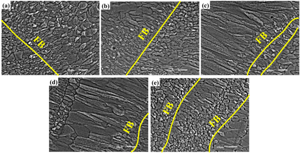
Figure 9. Microscopic pictures of AZ31 magnesium alloy of pulsed laser weld FB at different overlap rates: (a) Of = 10%; (b) Of = 30%; (c) Of = 50%; (d) Of = 70%; (e) Of = 90%.
Download figure:
Standard image High-resolution imageTable 5. Grain size of FB and weld center at different overlap rates.
| Overlap rate | 10% | 30% | 50% | 70% | 90% |
|---|---|---|---|---|---|
| Grain size of FB μm−1 | 15.66 ± 0.88 | 30.67 ± 1.17 | 84.07 ± 1.46 | 114.72 ± 3.06 | 35.98 ± 0.78 |
| Grain size of weld center μm−1 | 26.75 ± 1.97 | 53.96 ± 2.82 | 63.72 ± 3.95 | 74.08 ± 5.87 | 33.74 ± 3.21 |
It can be seen from figure 10 which shows the microstructure of the welds center at different pulse overlap rates that the grain type of the welds center is equiaxed grain. This is because the temperature gradient gradually decreases from the FB to the welding center, and the constitutional undercooling increases [20]. The grains from FB to the welding center change from columnar to equiaxed. As shown of table 5 that the grain size of the weld center increases and then decreases as the overlap rate increases. The grain size reaches a maximum of 74.08 ± 5.87 μm at 70% overlap rate. In the solidification process, the temperature gradient in the weld center is small, the solute is enriched around the grain boundary, the constitutional undercooling is large, and the nucleation rate is high, so it is easy to produce equiaxed grains in the weld center. The increasing overlap rate makes the welding heat input and grain growth time increase. Therefore, the coarse equiaxed crystals are formed. However, the grain size is reduced due to the remelting of overlapping pulses when the overlap rate is 90%. As a result, the equiaxed grain size of the weld center increases first and then decreases with the increases of the pulse overlap rate.
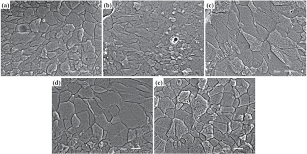
Figure 10. Microscopic pictures of the welding central area at different overlap rates: (a) Of = 10%; (b) Of = 30%; (c) Of = 50%; (d) Of = 70%; (e) Of = 90%
Download figure:
Standard image High-resolution image3.3. Mechanical properties
3.3.1. Tensile propertie
Figures 11, and 12 and table 6 show the tensile test and the stress displacement curves of the welds under different pulse overlap rates. It is readily apparent from figure 11 that all the fractures of the tensile specimens occur in the welding metal. This is because there are many defects such as cracks and pores in the weld, which have a great impact on the mechanical properties of the welds, resulting in the tensile strength of the weld decreases significantly and smaller than that of the BM.
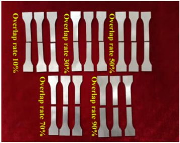
Figure 11. Fracture location of the butt joints.
Download figure:
Standard image High-resolution image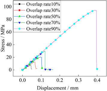
Figure 12. Effect of the overlap rates on the weld stress displacement curve.
Download figure:
Standard image High-resolution imageTable 6. Mechanical properties of tensile specimens at different overlap rates.
| Overlap rate | Maximum force/kN | Tensile strength/MPa | Elongation at break | Fracture location |
|---|---|---|---|---|
| 10% | 0.545 | 45.417 | 0% | Weld |
| 30% | 0.483 | 40.250 | 0.5% | Weld |
| 50% | 0.412 | 34.333 | 0.8% | Weld |
| 70% | 0.245 | 20.417 | 1% | Weld |
| 90% | 1.135 | 94.583 | 2.2% | Weld |
It is observed from table 6 that as the pulse overlap rate increases, the elongation at break increases, and the tensile strength and maximum force show a trend of first decreasing and then increasing. When the overlap rate is 90%, both of the tensile strength and the force reach the maximum values of 94.583 MPa and 1.135 kN. This is mainly because the increasing overlap rate increases the welding heat input, while the cooling rate of the melt pool slows down. As a result, the sensitivity of solidification cracks and pores is reduced.
Figures 13 –15 show the microstructure and partial enlargements of welding tensile fractures with the overlap rates of 50%, 70% and 90%, respectively. It is discernible that the fracture surface morphology of the welds with 50% and 70% overlap rate is mainly cleavage surface, most of which are intergranular fracture, with obvious tearing edge protrusion, a small number of dimples exist, showing the characteristics of brittle ductile mixed fracture, and the percentage of ductile fracture is relatively small. The fracture surface of the weld with 90% overlap rate is mainly composed of dimples, with a few tearing edges and cleavage steps, which increases the percentage of ductile fracture. This is because with the increases of the pulse overlap rate, the remelting occurs in the overlapping parts of the two pulses, which decreases the grain size. Therefore, the tensile strength and elongation of the welds increase, and the ductile fracture is prone to occur. Besides, the peak temperature of the molten pool increases with the increase of the overlap rate, which aggravates the burning loss of low melting point elements in the welds, increases the percentage of Al element, and plays a role in grain refinement. To sum up, a weld with better mechanical properties can be obtained when the overlap rate is 90%.
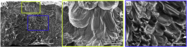
Figure 13. Fracture welds with overlap rate of 50%.
Download figure:
Standard image High-resolution image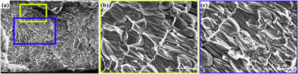
Figure 14. Fracture welds with overlap rate of 70%.
Download figure:
Standard image High-resolution image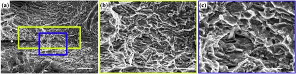
Figure 15. Fracture welds with overlap rate of 90%.
Download figure:
Standard image High-resolution image3.3.2. Hardness properties
According to the average values of the microhardnesses in the welds under different overlap rates in figure 16, the maximum and minimum of the microhardnesses are 86HV0.2 and 57 HV0.2, and that of the BM are 75 HV0.2 and 57 HV0.2, respectively. The maximum microhardnesses of the welds is 14.7% higher than that of the BM. The microhardnesses of the welds decrease first and then increase with the increases of the overlap rate. This is because there are some hard and brittle β-Mg17Al12 precipitated phases [19] dispersively distributed in the α-Mg solid solution, which play a role in dispersion strengthening. It can increase the hardness of the welds significantly. Therefore, the microhardnesses of the welds are higher than that of the BM. In addition, as can be seen from section 2, the grain size in the welds tends to increase first and then decrease. According to the Hall-Patch formula as shown of equation (6) [21], the reduced grain size increases the yield limit, which could increases the microhardnesses of the welds. It can be concluded that as the overlap rate increases, the microhardnesses of the welds decrease first and then increase.

Where σy is the yield limit of materials which is usually expressed as HV, σ0 is the lattice friction resulting from moving a single dislocation, Ky is a constant related to the type properties of the material, d is the average of grain size.
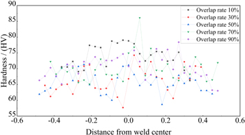
Figure 16. Effect of overlap rates on the average microhardnesses of the welds.
Download figure:
Standard image High-resolution imageFigure 17 shows the average microhardnesses of the FB inside the welds at different overlap rates. It is clear that the microhardnesses of the FB are higher than that of the welds, which have a maximum value of 88.3 HV0.2. Energy spectrum analysis is performed on the FB with different overlap rates, as shown in figure 18, and the results are shown in table 7. The results show that the content of Al element in the FB increases with the increases of the overlap rate. Besides, small cellular crystals are produced at the FB due to the remelting. Therefore, the microhardnesses of FB are greatly improved. It is readily apparent that with the increases of the overlap rate, the number of the FB inside the welds increases, which makes the average microhardness of the weld increase.
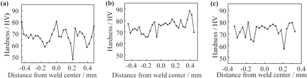
Figure 17. Effect of overlap rates on the average microhardnesses of the FB: (a) Of = 50%; (b) Of = 70%; (c) Of = 90%.
Download figure:
Standard image High-resolution image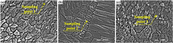
Figure 18. Energy spectrum analysis of weld FB: (a) Of = 50%; (b) Of = 70%; (c) Of = 90%.
Download figure:
Standard image High-resolution image
Table 7. Energy spectrum analysis results of sampling points in figure 18.
| Element | Sampling point 1 Wt% | Sampling point 2 Wt% | Sampling point 3Wt% |
|---|---|---|---|
| Mg | 94.32 | 93.97 | 88.99 |
| Al | 4.51 | 4.85 | 10.33 |
| Zn | 1.18 | 1.18 | 0.68 |
4. Conclusion
The effect of pulse overlap rates (10%, 30%, 50%, 70% and 90%) on the microstructure and mechanical properties of pulsed laser welding on the thin magnesium alloy is studied. The specific conclusions are as follows:
- (1)With the increases of pulse overlap rate, the widths of upper surface and lower surface of the welds increase from 1.30 mm and 0.25 mm to 1.93 mm and 0.96 mm, respectively. The sensitivity of solidification cracks and pores decreases and the undercut depth increases from 0.063 mm to 0.323 mm with the increases of the pulse overlap rate.
- (2)With the increase of pulse overlap ratie, the pore area and crack length decrease, and the undercut depth increases.
- (3)The grain size of the columnar grains at the FB and the equiaxed grains in the center of the welds increases and then decreases with the increases of the pulse overlap rate. When the overlap rate is 70%, the grain size reaches the maximum value of 114.72 ± 3.06 μm and 74.08 ± 5.87 μm, respectively.
- (4)The microhardnesses of the welds decrease with increasing overlap rate and then increase which reach the maximum value of 86 HV0.2 when the overlap rate is 70%. The microhardnesses of the welds is 14.7% higher than that of the BM. The maximum microhardness of the FB is 88.3HV0.2.
- (5)The greater the pulse overlap rate, the greater the heat input, so that the metal evaporation in the molten pool is greater than 70% when the overlap rate is 90%, and it is easy to produce subsidence on the weld surface. Therefore, the weld with better surface morphology can be obtained when the overlap rate is 70%. However, with the increase of heat input, the cooling time of molten pool will be reduced and the sensitivity of defects such as cracks will be reduced. Therefore, the weld with better mechanical properties can be obtained when the overlap rate is 90%. The fracture of the tensile specimen is a mixed ductile and brittle fracture. The elongation at break increases with the increase of pulse overlap rate, and the tensile strength and maximum force first decrease and then increase.
Acknowledgments
This work is supported by the Science and Technology Research Project of Education Department of Jilin Province (No.JJKH20220095KJ), Doctoral Research Initiation Fund of Northeast Electric Power University (Grant Number BSJXM-2021118).
Data availability statement
The data that support the findings of this study are available upon reasonable request from the authors.
Declarations of interest
None.