

Abstract
Iron-chromium redox flow battery (ICRFB) is a secondary battery capable of deep charge and discharge. It is a novel electrochemistric equipment for energy storage. ICRFB has around wide concern as it possesses advanced characteristics such as high energy, long cycle life, and environmental friendly. Graphite felt is a common electrode material for ICRFB because of its high temperature resistance, corrosion resistance, infinite specific surface area, and admirable electroconductibility. However, poor hydrophilicity and electrochemical activity lead to the graphite felt to be modified to be better applied in ICRFB. To improve the electrochemical activity of graphite felt, the PAN-based graphite felt was activated by boric acid thermal etching, and tested with SEM analysis, electrochemical analysis, and charge-discharge test. The results showed that the electrochemical activity and reversibility of boric acid thermal etching graphite felt impregnated with 25% boric acid solution were significantly improved after thermal treatment at 500 °C for 5 h. The Energy Efficiency of boric acid thermal etching graphite felt impregnated with 25% boric acid solution in ICRFB could reach more than 85%, which was about 9.5% higher than that of ICRFB with untreated graphite felt (1#) as electrode.
Export citation and abstract BibTeX RIS

Original content from this work may be used under the terms of the Creative Commons Attribution 4.0 licence. Any further distribution of this work must maintain attribution to the author(s) and the title of the work, journal citation and DOI.
1. Introduction
Iron-chromium redox flow battery (ICRFB) has the advantages of compact structure, long life, fast charge, and discharge and wide standard reduction potential, which is a new type of secondary battery with high efficiency, economy and environmental protection [1–3]. Electrode material is one of the key materials of redox flow battery, and its electrochemical characteristics directly affect the Energy Efficiency and power density of the redox flow battery [4–8]. Graphite felt is a widely used electrode material for ICRFB [9–11]. It has large specific surface area, strong oxidation resistance and corrosion resistance, and good electrical conductivity [12–15]. However, the problems of poor hydrophilicity and electrochemical activity of graphite felt have to be solved when it is used as an electrode material on a large scale in practical production and life [16–18]. A great deal of work has been done to improve the electrochemical properties of graphite felt [19–35]. Blasi et al treated four kinds of carbon materials, including carbon felt, carbon nanofibers, carbon paper, and graphite rod, by nitric acid oxidation method. The results show that the graphite structure with the appropriate oxygen content (4.0%–5.0%) is the most favorable for the electric pair redox reaction [36]. Wu et al first used microwave to heat the graphite felt electrode and found that the electrode obtained by microwave treatment at 400 °C for 15 min showed the best electrocatalytic activity. Compared with the electrode optimized by the traditional heat treatment method, the battery assembled by this electrode had higher efficiency [37]. Shao et al studied the catalytic effect of nitrogen-containing functional groups on redox electric pairs of nitrogen-doped mesoporous carbon prepared by soft template method. The results showed that the electrochemical activity of nitrogen-doped mesoporous carbon was significantly improved compared with that of non-nitrogen-doped mesoporous carbon and graphite electrode [38]. Inspired by the process of carbon carrying platinum in fuel cells, Wei et al used Nafion solution as the binder to load -OH functionalized carbon nanotubes on carbon felt at different mass ratios. The Cyclic Voltammetry test showed that the reversibility of the electric pair redox reaction on the carbon nanotube/carbon felt composite electrode was clearly enhanced with the increase of the carbon nanotube load. The constant current charge-discharge performance of the battery found that the load of carbon nanotubes significantly improved the efficiency of the battery [39]. The electrochemical reaction of ICRFB in the charge-discharge cycle is described as equations (1), (2) and (3):


Acid treatment and thermal treatment were considered the most 'convenient and effective' modification methods [40]. Sun Hong et al found that the number of oxygen-containing functional groups on the surface of the graphite felt electrode impregnated in 98% concentrated sulfuric acid for 5 h increased significantly, and the electrochemical activity increased. The effective specific surface area of the graphite felt heat treated at 400 °C for 30 h increased significantly, providing an active site for ion reaction, thus achieving the purpose of improving the performance of the redox flow battery [41]. P. Said Mazur et al found that the graphite felt under 400 °C heat treatment after 9 h used for the positive, negative, positive and negative poles of the battery, respectively. And compared with graphite felt electrode with unheated simple, the study found that: heat treatment of graphite felt was beneficial to the improvement of the redox flow battery cathode electrochemical properties, and the improvement of redox flow battery anode electrochemical activity. However, both above two research methods are single acid treatment or thermal treatment, and the safety and speed need to be improved. Therefore, this paper proposed to use boric acid thermal treatment of graphite felt to study its influence on the electrochemical performance of ICRFB [42].
2. Experiment
The graphite felt was purchased from Gansu Haoshi Carbon Fiber Co., Ltd Boric acid was purchased from Tianjin Kemiou Chemical Reagent Co., Ltd FeCl2·4H2O, CrCl3·6H2O and concentrated hydrochloric acid (HCl) were purchased from Shenyang Xindong Reagent Factory.
2.1. Sample preparation
In the process of production, transportation and storage, graphite felt will inevitably mix with impurities, which adhere on the graphite felt or in the pores of the fiber. If these impurities are not removed in advance, the modification of the catalyst on the surface of the graphite felt and the binding force between the modified catalyst and the graphite felt will be affected, resulting in the catalyst falling off, reducing the electrochemical performance of the electrode and affecting the cycle life of the ICRFB.
For the pretreatment of graphite felt, the graphite felt was put into deionized water and washed by microwave shock for 40 min with a microwave cleaner to remove insoluble impurities on the surface of the graphite felt, and the soluble impurities were dissolved in water. Then, the graphite felt was immersed in 1 mol l−1 NaOH solution in a water bath at 80 °C for 1 h to remove organic impurities. The graphite felt was removed and cleaned repeatedly with deionized water until pH = 7. The graphite felt was put into a drying oven to dry at 80 °C for later use.
Weighed boric acid of different weights, added deionized water to 100 mL at constant volume and stirred magnetically for 60 min to prepare boric acid solutions of different concentrations. The pretreated graphite felt was immersed in different concentrations of boric acid solution and dispersed by ultrasonic shock for 5 h. The graphite felt impregnated with different concentrations of boric acid solution was put into a blast drying oven and dried at 80 °C. Graphite felt impregnated with boric acid solution was thermal treated in a tubular furnace. The specific process system is shown in table 1.
Table 1. Preparation process parameters of each sample.
| Sample | Temperature | Time | Concentration of boric |
|---|---|---|---|
| 1# | 25 °C | 5 h | 0% |
| 2# | 500 °C | 5 h | 0% |
| 3# | 500 °C | 5 h | 25% |
| 4# | 500 °C | 5 h | 50% |
2.2. Characterization
The surface morphology of graphite felt was observed by Nova Nano SEM 450Ar scanning electron microscope. The electrochemical parameters of ICRFB were measured and controlled by the RST5200F electrochemical workstation produced by Zhengzhou Shiruisi Instrument Technology Co., Ltd The saturated calomel electrode was used as the reference electrode and the graphite plate as the auxiliary electrode. The electrolyte solution is 1 mol l−1 FeCl2 + 1 mol l−1 CrCl2 + 3 mol l−1 HCl solution. The graphite felt was electrochemically tested in the voltage range of 0 ∼ 0.8 V(versus SCE) with a cyclic voltammetry at a scanning rate of 3 mV s−1. The polarization potential (η) measured by ac impedance of positive and negative graphite felt is 0.4 V (versus SCE) and −0.5 V (versus SCE), respectively. The specific surface area of graphite felt samples was measured and characterized by Quantachrom (Autosorb-iQ2). The resistance of graphite felt with an area of 3 cm×3 cm and a thickness of 5 mm was measured by double-electrode method. The surface morphology and surface functional groups of electrode materials were characterized by x-ray photoelectron spectroscopy (XPS). The charging and discharging cycle of ICRFB was monitored by 5V2A8C-KQ charge and discharge tester manufactured by Wuhan Landian Electronics Co., Ltd The voltage range of the charging and discharging cycle was 0.8V–1.2 V The performance of ICRFB is characterized by the Coulomb Efficiency (CE), Voltage Efficiency (VE) and Energy Efficiency (EE). The respective calculation formulas are shown in equations (4), (5) and (6):


In the equations above, Qdischarge and Qcharge stand for Discharge Capacity (mAh/L) and Charge Capacity (mAh/L), respectively. Vdischarge and Vcharge represent Discharge Voltage (V) and Charge Voltage (V), respectively.
3. Results and discussion
3.1. Physical properties characterization
Graphite felt with good wettability is easier to absorb electrolyte solution, which is conducive to the reaction of iron and chromium ions on the surface of graphite felt. The graphite felt was cut into small pieces of equal size and placed in a test tube with electrolyte at the same time to observe the water absorption of the sample in an instant, after 10 min and after 30 min in the electrolyte. As can be seen from figure 1, the hydrophilicity of graphite felt after boric acid thermal etching was significantly enhanced, and it sank in the electrolyte at the moment of contact. The hydrophilicity of graphite felt can be measured by this method, which may lead to a large error, and the result is not necessarily accurate. However, it can be confirmed that the hydrophilicity of graphite felt is enhanced after boric acid thermal etching.

Figure 1. Hydrophilic test results of each sample: in an instant (a), after 10 min (b), after 30 min (c).
Download figure:
Standard image High-resolution imageTo better understand the performance of boric acid thermal etching graphite felt, we measured the resistance of each sample, as shown in figure 2. According to figure 2, with the increase of the concentration of boric acid solution, the resistance value presents a decreasing trend.
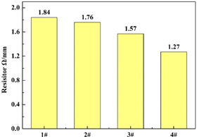
Figure 2. Resistance of each sample.
Download figure:
Standard image High-resolution imageFigure 3 shows the surface morphology of each sample under Scanning Electron Microscope. It's can be seen from figures 3(a)–(b), the untreated graphite felt (1#) surface has a small amount of impurities attached along the fiber direction of the shallow 'groove', and after thermal treatment of the surface of the graphite felt (2#) appear a large number of deep longitudinal ridges, the surface with the boric acid thermal etching graphite felt appear a large number of circular hole, and the number and diameter of the hole are increased with the increase of concentration of boric acid solution. When the boric acid concentration was 25% (3#), the specific surface area of graphite felt reached 3.614 m2 g−1, which was 3.6 times that of untreated graphite felt (1#).
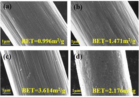
Figure 3. SEM at 10.00 KX of each sample: (a) 1#, (b) 2#, (c) 3#, (d) 4#.
Download figure:
Standard image High-resolution imageFigure 4 shows the XPS full spectrum of each sample. Compared with 1#, the C content in 2# decreased by about 7%, while the C content in 3# and 4# samples decreased by about 10% and 8% respectively after boric acid thermal etching. Accordingly, the content of O in 2# sample increases, and both the boric acid thermal etching samples are higher than 2#. Figure 5 shows the quantization results of high-resolution O 1 s peaks for each sample. The O1s nuclear polarography is divided into three peaks at binding energy of 531.8, 533, and 535 eV, respectively, corresponding C=O, C-OH, other ether-like species [43]. The surface structure content of each sample is listed in table 2. The results showed that the number of oxygen functional groups of 2#−4# increased significantly compared with that of 1#, and the number of C=O and C-OH oxygen functional groups of 3# increased significantly, which was about 4 times of that of 1#. The results confirm that boric acid thermal etching significantly increases the number of oxygen functional groups on the surface of the graphite felt.

Figure 4. XPS full spectrum of samples.
Download figure:
Standard image High-resolution image
Figure 5. O 1 s XPS fitting of 1# (a), 2# (b), 3# (c), 4# (d).
Download figure:
Standard image High-resolution imageTable 2. Quantitative results of O1s peaks in each sample.
| Samples | O 1s (%) | ||
|---|---|---|---|
| C=O (531.1 ± 0.8 eV) | C–OH (532.7 ± 0.8 eV) | Other (535 eV) | |
| 1# | 1.17 | 1.76 | 0.04 |
| 2# | 3.84 | 4.31 | 1.98 |
| 3# | 5.93 | 6.48 | 1.23 |
| 4# | 4.40 | 5.57 | 1.36 |
3.2. Electrochemical characterization
Figure 6 shows the Cyclic Voltammetry curves of 1#−4# graphite felt as working electrode. As can be seen from figures 6(a)–(b), the reaction of untreated graphite felt (1#) is reversible within the scanning range, but the redox peak strength is weak, indicating that the untreated graphite felt (1#) has poor electrochemical activity and is not suitable to be directly used as the electrode material of ICRFB. The redox peak of graphite felt electrode after thermal treatment and boric acid thermal treatment is more obvious, indicating that the electrochemical performance of graphite felt electrode after thermal treatment is significantly improved compared with that of untreated graphite felt (1#) electrode. Among them, the 3# graphite felt electrode has the best electrochemical performance and the peak value is more obvious. As can be seen from table 3, the peak current values of the positive electrode of graphite felt after boric acid thermal etching are 594 mA, 937 mA and 844 mA, all greater than 412 mA, and the peak current values of the negative electrode are 265 mA, 385 mA and 331 mA, all greater than 212 mA. It can be proved that boric acid thermal etching can improve the electrochemical activity of redox pairs of ICRFB.
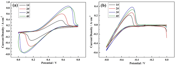
Figure 6. Cyclic Voltammetry at a scan rate of 3 mV s−1 in 1.0 mol·l−1 CrCl3 + 1.0 mol·l−1 FeCl2 + 3.0 mol·l−1 HCl :(a) 0 ∼ 0.8 V(versus.SCE), (b) −0.8 ∼ 0 V(versus.SCE).
Download figure:
Standard image High-resolution imageTable 3. Parameters obtained from figure 6 for the redox couple.
| Sample | Fe2+/Fe3+ | Cr3+/Cr2+ | ||||||
|---|---|---|---|---|---|---|---|---|
| Epa(V) | Epc(V) | Ipa(mA) | Ipc(mA) | ΔEp(V) | Ipa/Ipc | E(V) | I(mA) | |
| 1# | 0.570 | 0.177 | 363 | 412 | 0.393 | 0.881 | −0.495 | 212 |
| 2# | 0.570 | 0.175 | 464 | 594 | 0.395 | 0.781 | −0.471 | 265 |
| 3# | 0.666 | 0.080 | 823 | 937 | 0.586 | 0.878 | −0.458 | 385 |
| 4# | 0.681 | 0.066 | 742 | 844 | 0.615 | 0.879 | −0.446 | 331 |
In table 3, Epa and Epc stand for the peak voltage value of anode and cathode, respectively. Ipa and Ipc represent the peak current value of anode and cathode, respectively.
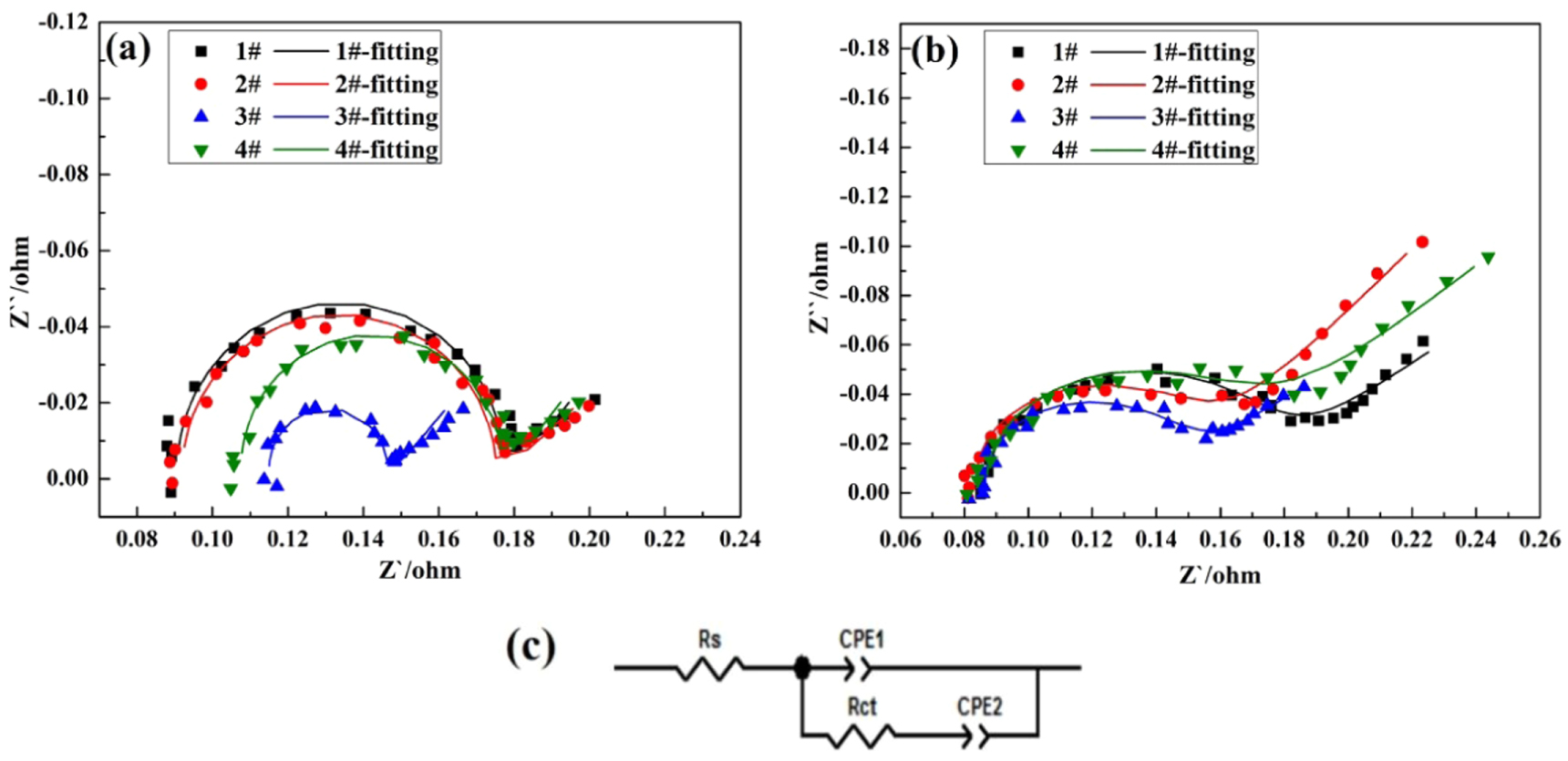
Table 4. Parameters obtained from fitting the EIS plots with the equivalent circuit.
| Sample | η/V(versus SCE) | Rs/Ω·cm2 | Rct/Ω·cm2 |
|---|---|---|---|
| 1# | 0.4 | 0.089 | 0.095 |
| 2# | 0.090 | 0.089 | |
| 3# | 0.114 | 0.034 | |
| 4# | 0.104 | 0.075 | |
| 1# | −0.5 | 0.085 | 0.113 |
| 2# | 0.080 | 0.111 | |
| 3# | 0.081 | 0.079 | |
| 4# | 0.081 | 0.104 |
The effect of H3BO3 and thermal treatment on the electrochemical performance of ICRFB was further analyzed by Electrochemical Impedance Spectroscopy (EIS). The Nyquist diagram of 1#−4# graphite felt electrodes is shown in figures 7(a)–(b). The parameters of each component in the equivalent circuit fitted by EIS are listed in table 4. Each Nyquist diagram has a semicircle part in the high frequency region and a linear part in the low frequency region, indicating that the redox reaction on the graphite electrode is affected by both charge transfer and diffusion velocity [44]. In figure 7(c), the semi-circular arc in the high frequency region corresponds to the electrode process when the electron transfer step of the electrolyte/electrode interface is the control step. The size of the charge transfer resistance (Rct) reflects the difficulty of electron transfer reaction. The smaller the radius and the smaller the resistance, the easier the electron transfer reaction is. The ohmic resistance (Rs) at low and medium frequencies corresponds to the electrode process when the diffusion coefficient of the reaction particles in solution is the control step [45]. According to the figure 7 analysis, the charge transfer resistance of Fe/Cr redox pairs can be significantly reduced by boric acid thermal etching, and the radii of high-frequency arcs are significantly smaller than before treatment, indicating that boric acid thermal etching can accelerate the redox reaction and the charge transfer rate of Fe/Cr electric pair. However, the charge transfer resistance of graphite felt after boric acid thermal etching is significantly reduced, which further proves that the electrochemical performance of graphite felt after boric acid thermal etching is improved.

Figure 7. EIS spectroscopy and equivalent circuit diagram (c).
Download figure:
Standard image High-resolution image3.3. Cell test
Figure 8 shows the influence of 1#−4# samples on the Energy Efficiency and Voltage Efficiency of ICRFB at different current densities. It should be noted that each current density shown in figure 8 is the average value of five charge-discharge cycles under this current density. As can be seen from figures 8(a)–(b), the charge-discharge efficiency of ICRFB treated with boric acid thermal etching is higher than that of the untreated ICRFB, and the charge-discharge efficiency of the 3# battery is the highest. It can be concluded that the suitable boric acid thermal etching graphite felt can effectively improve the electrochemical performance of ICRFB as the anode. What's more, in a concentration of 25% boric acid solution impregnated graphite felt at 500 °C under the condition of heat treatment 5 h of graphite felt the highest electrochemical activity, used in ICRFB Energy Efficiency can reach above 85%, than use without electroplating graphite felt the electrode of ICRFB increases by about 9.5%. At high current density, the electrochemical performance of ICRFB is improved by boric acid thermal etching. When the current density is 60 mA cm−2, the Energy Efficiency and Voltage Efficiency of the 3# graphite felt are increased by 9.5% and 11.31% compared with that of the 1# graphite felt ICRFB. When the current density is 120 mA cm−2, the Energy Efficiency and Voltage Efficiency of ICRFB with 3# graphite felt are increased by 10.32% and 12.55% compared with that of 1# graphite felt. However, excessive boric acid thermal etching is not beneficial to improve the electrochemical performance of ICRFB.
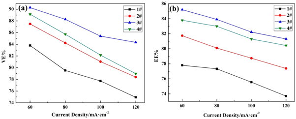
Figure 8. Efficiency of iron-chromium redox flow battery at 60, 80,100 and 120 mA cm−2: Energy Efficiency (a), Voltage Efficiency (b).
Download figure:
Standard image High-resolution imageFigure 9 shows the changes of charging capacity and discharging capacity of every ICRFB under different current densities. It can be seen from figures 9(a)–(b) that the charging capacity and discharging capacity decrease with the increase of current density. When the current density is 60 mA cm−2 (number 1–5 cycle), the charging capacity and discharging capacity of ICRFB treated with 25% boric acid thermal etching increase by 10.66% and 9.45% compared with the untreated ICRFB. When the current density is 120 mA cm−2 (number 15–20cycle), the charging capacity and discharging capacity of ICRFB treated with 25% boric acid thermal etching are increased by 20.32% and 9.36% compared with that of the untreated one. Therefore, it can be concluded that an appropriate amount of boric acid thermal etching graphite felt as the negative electrode of ICRFB can slow down the attenuation of charge and discharge capacity. The effect of boric acid thermal etching on reducing the capacity decay of charge-discharge cycle is more prominent at high current density, because boric acid thermal etching enables the negative graphite felt electrode to stand faster charge transfer and effectively reduce the polarization phenomenon.

Figure 9. Capacity of iron-chromium redox flow battery: Charge Capacity (a), Discharge Capacity (b).
Download figure:
Standard image High-resolution image
4. Conclusion
In this paper, the electrode was prepared by the method of weak acid (boric acid) combined with conventional thermal oxidation in air. Boric acid in the process of heat treatment intensified the etching degree of graphite felt in hot air, formed holes, effectively increased the working area of graphite felt, effectively. The combination of boric acid and thermal oxidation not only increased the active sites but also decreased the conductivity of the graphite felt and enhanced the wettability and electrochemical activity of the graphite felt. Therefore, the results of Brunauer–Emmett–Teller, Scanning Electron Microscopy analysis, Electrochemical analysis and charge-discharge test were combined to obtain the following conclusions:
- (1)Boric acid thermal etching can increase the content of oxygen functional groups C=O and C–OH in graphite felt, and improving the electrochemical performance of ICRFB effectively. The electrochemical performance of the boric acid thermal etching ICRFB is significantly improved at high current density.
- (2)Boric acid thermal etching can slow down the attenuation of Charging and Discharging Capacity of ICRFB. In the process of increasing the current density from 60 mA cm−2 to 120 mA cm−2, the Charging Capacity of untreated 1# ICRFB decays 44.90%, and the charging capacity of 3# battery treated with boric acid thermal etching decays 40.09%.
We hope to explore a new way to propose a convenient and cheap modification method for preparing graphite felt electrode for ICRFB.
Acknowledgments
We gratefully acknowledge the assistance of 'Integrated demonstration of high value utilization technology and base for solid waste chemical materials of magnesite, Grant/Award Number: 2020YFC1909300'; 'Scientific research fund project of Provincial Department of Education: Study on properties and damage mechanism of synthetic Magnesium calcare-resistant materials, Grant/Award Number: L2020005' ; And 'Study on electric conversion and resynthesis of molten salt after decomposition of lithium cobalate as cathode material of waste lithium battery, Grant/Award Number: ZJNK2107'.
Data availability statement
The data that support the findings of this study are available upon reasonable request from the authors.
Conflict of interest
Authors have no conflict of interest to declare.