
Abstract
The properties of lithium ion battery largely depend on the structure of active materials. In the present work, CoFe2O4 nanowire arrays /Cu foam three-dimensional integrated electrode (denoted as CFO/Cu-foam NWAs) was firstly designed and synthesized via a simple hydrothermal method follow annealing as a binder-free anode for lithium ion battery. The CoFe2O4 nanowires with diameter of 50–100 nm are uniformly anchored on the porous conductive substrate. Lithium ion battery based on the CFO/Cu-foam NWAs integrated electrode exhibits a high initial capacity of 882.7 mAh · g−1 and excellent cyclic stability of 832.1 mAh · g−1 after 100 cycles at 1.0 A · g−1 which is much better than traditional coated electrode of CoFe2O4 nanowire (defined as CFO NWAs) and CoFe2O4 nanowire/Cu foil integrated electrode (named CFO/Cu-foil NWAs). The improved electrochemical performance might be attributed to superior conductivity and porous skeleton structure which not only reduce contact resistance and polarization, but also relieve volume alteration during the lithiation/delithiation process. These advantages make the CoFe2O4 /Cu foam integrated electrode a promising anode for Li-ion batteries.
Export citation and abstract BibTeX RIS

Original content from this work may be used under the terms of the Creative Commons Attribution 4.0 licence. Any further distribution of this work must maintain attribution to the author(s) and the title of the work, journal citation and DOI.
1. Introduction
Lithium ion batteries (LIBs) have the advantages of large capacity, long cycling life, no memory effect and environmental friendliness, which made them the main devices of various portable devices and energy storage devices [1]. However, commercial graphite anode materials with low theoretical capacity (372 mAh · g−1) [2], which are unable to meet the growing capacity requirements of lithium ion batteries. Transition metal oxides (TMO) have been studied for decades due to the high capacity, environmental friendly and low cost. Among multifarious TMO, CoFe2O4 (CFO) has gained a lot of attention owing to the advantage of nontoxicity, structural stability, low operating potential and high theoretical capacity (914 mAh · g−1), and has become potential electrode material [3–5].
But CoFe2O4 as anode also has some shortages, such as low electron/ion conductivity and relatively large volume expansion after lithiation/deionization, latter will lead the active material detached from the electrode, and further leads to poor cycle performance of battery [6–8]. In the past decade, three main strategies have been adopted to design and improve the cycling stability of lithium ion battery anodes. The first strategy is to achieve high specific surface area through appropriate micro/nano structure design, thus providing shorter diffusion path for ions and electrons, and more active sites for energy storage and transformation [9]. TMO has been designed and fabricated into various nanostructures, such as nanoparticles [10], nanowires [11], nanosheets [12], nanorods [13], etc. The second strategy is to manufacture transition metal oxide based composites, which also improve the performance of lithium ion batteries in terms of conductivity, mechanical strength and specific surface area, such as carbon materials decorated composites [14–16], TMO/metal oxides composites [17, 18], TMO/transition metal dichalcogenides [19, 20], etc. In addition, some researchers have explored how to improve the conductivity of active materials by doping conductive materials, including anionic doping [13, 21, 22], positive hole [23, 24], and so on.
The third strategy is to design three-dimensional (3D) collector with stable structure. On the one side, reasonable structure design can increase the position of nucleation and reduce the aggregation of active substances. On the other hand, it can buffer the volume effect of charge/discharge process and decrease interfacial resistance. Traditionally, in order to make the active substance adhere to the conductive collector, a polymer binder, polyvinylidene fluoride (PVDF) is usually necessary, however the electrochemically inert binder can reduce the conductivity of the electrode and inhibit the ion transport. Thus, a binder-free structure design is a promising way to achieve high energy density and cyclic stability of lithium ion batteries. Based on these reasons, a lot of researches have been focused on the three-dimensional structure of binder-free conductive collector, including electro-deposition [25], in situ growth [25–29] on the 3D conductivity substrate, etc.
Motivated by the above research, it is feasible to improve the electrochemical performance of CoFe2O4 anode by reasonable electrode structural design. In this work, CFO nanowire arrays were grown on copper foam collector by convenient hydrothermal method and subsequent annealing treatment. Compared with traditional electrodes, this integrated electrode has many obvious advantages: (1) these nanostructured arrays arranged on the conductive substrate of copper foam 3D structure, high conductivity copper foam substrate not only acts as a physical support for such nano arrays, but also acts as a support to disperse CFO nanowires and avoid agglomeration, thus ensuring a large amount of activity sites, which is conducive to the maximum utilization of electrochemically active materials [11, 30]; (2) there is enough free space between CFO nanowire arrays, which allows Li+ pass through the interface quickly, and alleviate the volume change of active substances in the discharge charging process, so as to reduce the shedding of active substances from the collector and improve the cycle stability. For comparison, the traditional electrode of CFO powder coating on copper foil is prepared, and the sample of CFO in situ grown on copper foil is also synthesized. The morphology, crystalline structure, and electrochemical performance of the integrated anode were analyzed.
2. Experimental section
2.1. Material preparations
The integrated anode was simply synthesized via a simple hydrothermal followed by annealing. The schematic illustration of the synthesis process for the CFO NWAs, CFO/ Cu-foil NWAs, CFO/Cu-foam NWAs was shown in figure 1. Before synthesis, the circular copper foils and foam copper substrates with 12 mm diameter were ultrasonic cleaned in acetone, ethanol and ultrapure water respectively, and then vacuum drying as pre-treated substrate. In a typical synthesis, Co(NO3)2 · 6H2O (0.5 mmol) and Fe(NO3)3 · 9H2O (1 mmol) were added to 35 ml deionized water successively, then urea (CH4N2O) (8 mmol) and NH4F (4 mmol) were added, the solution was stirred during the whole course. Then the solution and the pre-treated substrates were transferred to stainless steel autoclave lined with Teflon. The autoclave was sealed at 140 °C for 4 h. After cooling, the hybrid anode was washed using deionized water and ethanol for several times, and then dried in a vacuum oven at 60 °C for 12 h. The final CFO nanowire arrays integrated electrodes were obtained by heat treatment at 400 °C at a heating rate of 3 °C min−1 for 2 h and then cooled in the furnace with high purity argon as protective gas. For comparison, the hydrothermal reaction products in Teflon linings were collected, cleaned, dried and annealed to obtain CFO powder samples as reference groups.
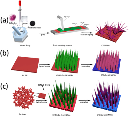
Figure 1. Schematic illustration of the synthesis process for CFO NWAs, CFO/ Cu-foil NWAs, CFO/Cu-foam NWAs.
Download figure:
Standard image High-resolution image2.2. Material characterizations
The phase was detected by Panalytical X'Pert x-ray diffractometer (Holland) using Cu-Kα radiation. The microstructure of the specimens was conducted by scanning electron microscope (S-3400, Hitachi). The fine microstructure and electron diffraction pattern were detected by the TEM (TESCAN, MIRA3). X-ray photoelectron spectroscopy (XPS) data was recorded using a K-Alpha XPS spectrometer (Thermo ESCALAB 250XI).
2.3. Electrochemical measurements
For the electrochemical measurements, the as-prepared CFO/Cu-foam NWAs and CFO/Cu-foil NWAs integrated electrodes was used as the anodes directly. But for the control group of CFO powder, the anode needs prepared by the following procedure. First, the active material, acetylene black and polyvinylidene fluoride with the weight ratio of 7:2:1 was mixed uniformly. Afterwards, the slurry was evenly covered on the copper foil, and then dried under vacuum at 60 °C for 12 h.
The electrolyte was comprised of 1.0 M LiPF6 in a dimethyl carbonate and ethylene carbonate mixture (DMC:EC, 1:1, v/v). Lithium metal plate was used as counter electrode and Celgard 2400 (Ф 19 mm) microporous membrane was used as diaphragm. The CR2032 coin cell was assembled in glove box with the concentration of H2O and O2 was controlled to lower than 0.01 ppm.
The cyclic voltammetry (CV) measurements at a scanning rate of 0.2 mV·s−1 over the potential range of 0.01–3.0 V were conducted on the electrochemical workstation (CHI660A, CH Instruments Ins, Shanghai, China). The charge/discharge profiles with a voltage range of 0.01–3.0 V (versus Li/Li+) were recorded on a battery test instrument (CT4008, Neware Electronics Co., Ltd, Shenzhen, China). Electrochemical impedance spectroscopy (EIS) test was conducted on the workstation (versa satt3 Princeton) with the frequency range of 105-10−2 Hz and AC voltage amplitude of 5 mV as the perturbation. All electrochemical measurements were carried out at room temperature.
3. Results and discussion
3.1. Characterization of electrode structure
The crystalline phase of CFO NWAs, CFO/Cu-foil NWAs, CFO/Cu-foam NWAs was confirmed by XRD and shown in figure 2. For the XRD pattern of CFO NWAs (figure 2(a)), all the peaks were indexed as (220), (311), (400), (422), (511), (440) and (533) crystal planes of spinel phase CoFe2O4 (JCPDS, No.22-1086), respectively. But in the XRD pattern of CFO/Cu-foil NWAs (figure 2(a)), except for the diffraction peaks of spinel phase CoFe2O4, there is some impurities which assigned to the substrate copper and oxide of copper. With respect to the XRD pattern of CFO/Cu-foam NWAs (figure 2(b)), only the diffraction peaks of the substrate of foam copper and spinel phase CoFe2O4 can be detected, implies the synthesis of CFO on the Cu foam substrate.
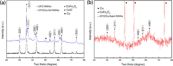
Figure 2. XRD patterns of CFO NWAs, CFO/Cu-foil NWAs, and CFO/Cu-foam NWAs.
Download figure:
Standard image High-resolution imageThe elemental components and the electronic states of the CFO/Cu-foam NWAs can be demonstrated by XPS analysis. The sample contains Cu, Co, Fe, O elements and C which possibly originate from the adsorbed carbonaceous materials as shown in the entire spectrum in figure 3(a) [8]. For the high-resolution Co 2p spectrum (figure 3(b)), there are two dominating peaks centered at 780.9 and 796.6 eV, which belong to Co 2p3/2 and Co 2p1/2, respectively. The bond energy difference between the two peaks is about 15.7 eV, indicating that the Co ion is in the typical bivalent formal oxidation state (Co2+). For the deconvoluted Fe 2p spectrum (figure 3(c)), the first two fitting peaks (located at 711.5 eV and 712.8 eV) of Fe 2p3/2 are correspond to the tetrahedral and octahedral sites, respectively. However, the higher peaks with the binding energy of 723.3 eV and 726.2 eV can be attributed to Fe 2p1/2, which is typical feature of Fe3+ ion [8, 31]. In the high-resolution O 1s spectrum (figure 3(d)), the strong peak at 529.6 eV can be attributed to the lattice oxygen of CFO, while another peak at 531.4 eV is due to the chemical adsorption or dissociated oxygen, or OH species on the surface of CFO [6, 31].
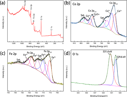
Figure 3. XPS spectrum of the CFO/Cu-foam NWAs specimen: (a)survey spectrum, the high-resolution spectrum of (b) Co 2p, (c) Fe 2p, and (d) O 1s.
Download figure:
Standard image High-resolution imageThe microstructure of as-prepared materials was exhibited by SEM and TEM. The low- and high-resolution SEM images of CFO powders are shown in figures 4(a) and (b). From figure 4(a), CFO partilces grow into a needle shapes with diameters of about 80–150 nm and aggregate into flower like structures. The high resolution image in figure 4(b) further reveals the needles like structure of the flowers are growing in all direction and radially agglomerated. For CFO/Cu-foil NWAs sample, except for the similar flower like structure, there is some spherical particles on the surface of Cu foil (figures 4(c) and (d)). Different from the CFO grown on the copper foil, on the surface of copper foam, the needle like CFO crystals grow along the direction perpendicular to the surface. As shown in figures 4(e) and (f), the foam copper skeleton has been covered by ordered CFO nanowires, which clearly shows that CFO nanocrystals anchored on conductive foam copper. The large surface area of nanowires can significantly provide many active sites and shorter diffusion distance between electrode and electrolyte to improve electrochemical performance [32].
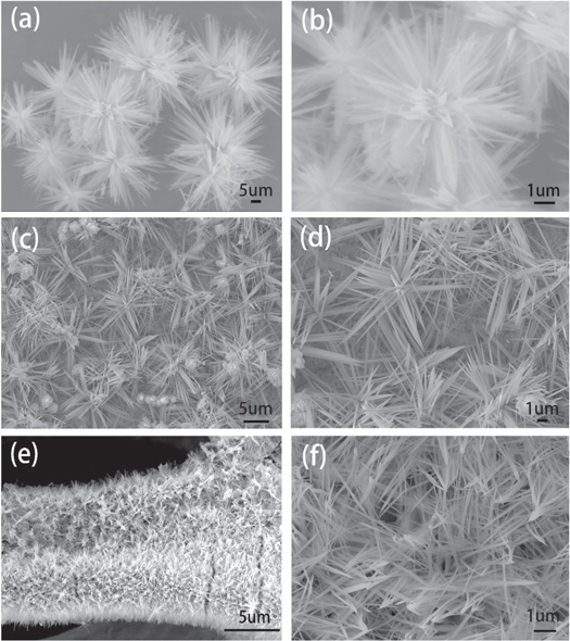
Figure 4. SEM images of CFO NWAs (a) and (b), CFO/Cu-foil NWAs (c) and (d), and CFO/Cu-foam NWAs (e) and (f).
Download figure:
Standard image High-resolution imageFor further study the structural characteristics of CFO nanowires, the CFO nanostructures were stripped from the surface of CFO/Cu-foam NWAs electrodes for TEM observation. The TEM images in figure 5(a) and locally enlarged image of area 1 in figure 5(b) show the needle structure of CFO and the average diameter of CFO nanowires are about 100 nm, which is unanimous with the SEM images. Next high-resolution image (HRTEM) (figure 5(c)) indicates the crystal structure of the sample is stable with regular lattice fringes of 0.265 nm, corresponding to the (311) plane of cubic CFO. Besides, the selected area electron diffraction (SAED) image in figure 5(d) demonstrates the cubic crystal of CFO, the diffraction spots can be indexed to planes of (311) and (3 1), which is corresponding with the results of XRD and HRTEM.
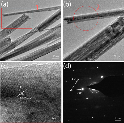
Figure 5. (a) TEM image of CoFe2O4 nanowires stripped from CFO/Cu-foam NWAs, (b) locally enlarged image of area 1 in (a), (c) HRTEM image of region 2 marked in (b), (d) the SAED pattern of the nanowire.
Download figure:
Standard image High-resolution image3.2. Electrochemical performances
In order to study the effect of introduction binder-free conductive foam substrate on the electrochemical performance, the CFO NWAs, CFO/Cu-foil NWAs and CFO/Cu-foam NWAs integrated electrode were evaluated as anode for lithium batteries.
Figure 6 shows the similar cyclic voltammetry (CV) characteristics of the three kinds electrodes in the initial three consecutive cycles at a scan rate of 0.2 mV·s−1 in the potential range from 0.01–3.0 V versus Li/Li+, which indicating similar electrochemical reactions. For the CV curves of CFO/Cu-foam NWAs as anode (figure 6(c)), in the first cathodic process, a sharp peak at ~0.5 V corresponds to the reduction of Co2+ and Fe3+ to their metallics states with the formation of Li2O (equation (1)), as well as the formation of solid electrolyte interface (SEI) film. In the following cycle, the reduction peak shifts to higher potential due to the electrode polarization during the initial charge-discharge process. In the anodic process, there are two broad peaks at about 1.70 V and 1.83 V can be ascribed to the oxidation of Co and Fe to their oxide states (equation (2)), different from the cathodic process, the oxidation peak did not drift to a higher potential after first scanning. It is worth noting that the peak intensity of second and third cycles for CFO NWAs anode (figure 6(a)) are obvious different, but for CFO/Cu-foam anode (figure 6(c)), the following CV curves incline to be stable and overlap well, which means that the CFO/Cu-foam NWAs electrode has good electrochemical reversibility and cyclic stability.


Figure 6. Typical cyclic voltammetry curves of CFO NWAs anode (a), CFO/Cu-foil NWAs anode (b), and CFO/Cu-foam NWAs anode (c) at a scan rate of 0.2 mV·s−1.
Download figure:
Standard image High-resolution imageThe galvanostatic discharge/charge process was illustrated in the 1st, 2nd, 3rd, 50th, and 100th cycles at current density of 1.0 A·g−1 for three kinds electrodes (figures 7(a)–(c)). The initial discharge capacity of CFO NWAs, CFO/Cu-foil NWAs, CFO/Cu-foam NWAs are less distinctive, which are 1304.4, 1238.3, 1227.6 mAh·g−1, respectively. In addition, in the first discharge process of CFO/Cu-foil NWAs, CFO/ Cu-foam NWAs electrodes, there is a voltage platform at about 0.7 V, which corresponds to the conversion reaction in equation (1), the result is consistent with CV measurement in the first cycle, as shown in figure 6. The initial coulombic efficiency (ICE) for CFO/Cu-foam NWAs is 71.9% which is higher than CFO/Cu-foil NWAs with the ICE of 69.9%, however, the ICE for CFO NWAs is only 51.5%. The irreversible loss of capacity may be caused by the SEI layer in the initial cycle. Figure 7(d) further makes a comparison on cycling performances of CFO NWAs, CFO/Cu-foil NWAs, CFO/Cu-foam NWAs. CFO/Cu-foam NWAs exhibits the higher discharge capacity (882.7 mAh·g−1) of the second cycles and capacity retention (832.1 mAh·g−1) after 100 cycles than those of CFO NWAs (365.8 mAh·g−1), CFO/Cu-foil NWAs (585.6 mAh·g−1). Obviously, CFO/Cu-foam NWAs anode has excellent cycling characteristics due to sufficient buffer volume variation during the cycle.

Figure 7. Typical discharge-charge curves of (a) CFO NWAs, (b) CFO/Cu-foil NWAs, (c) CFO/Cu-foam NWAs with the current density of 1.0 A·g−1, (d) Capacity and coulombic efficiency as a function of cycle number at a current density of 1.0 A·g−1.
Download figure:
Standard image High-resolution imageThe rate performance of CFO NWAs, CFO/Cu-foil NWAs and CFO/Cu-foam NWAs electrodes at current densities of 100 mA·g−1, 200 mA·g−1, 500 mA·g−1 and 1000 mA·g−1 are shown in figure 8. With the increase of current density from 100 mA·g−1 to 1000 mA·g−1, a slowly attenuation of the capacities for the three electrodes, this may imply that the electrode reaction is controlled by diffusion process [33]. Significantly, when the current drops back to 100 mA·g−1, a high capacity of 976.1 mAh·g−1 for CFO/Cu-foam NWAs can be regained, which indicating good reversibility and cyclic stability of the electrode. But for CFO/Cu-foil and CFO NWAs anodes, the energy density regained are 763.1 mAh·g−1 and 535.3 mAh·g−1, respectively. The excellent performance of the CFO/Cu-foam NWAs electrode is main benefit from nano-scale active materials on framework of copper foam and without binder.
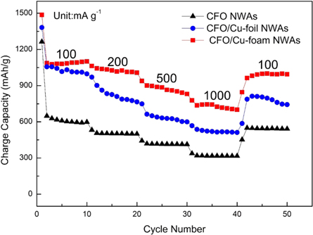
Figure 8. Typical discharge capacities at different rates of 100–1000 mA·g−1 for CFO NWAs anode, CFO/Cu-foil NWAs anode and CFO/Cu-foam NWAs anode.
Download figure:
Standard image High-resolution imageIn order to reveal transport kinetics of electron and Li+ in the anodes, three kinds electrode were investigated by electrochemical impedance spectroscopy (EIS) analysis. As shown in figure 9, the Nyquist curve consisted a high-frequency semicircle, the diameter of the semicircle represented the charge transfer resistance (RCT) and a linear in the low-frequency region which related to the diffusion coefficient of Li+ [34]. Compared with CFO NWAs (RCT = 225.4 Ω) and CFO/Cu-foil NWAs (RCT = 178.6 Ω), the semicircle diameter of CFO/Cu-foam NWAs electrode (RCT = 45.1 Ω) is smaller, which indicates that the charge transfer rate is faster in CFO/Cu-foam NWAs electrode and confirms that the electrochemical kinetics of the anode is enhanced and the charge transfer process is accelerated. The slope of the CFO/Cu-foam NWAs electrode can be clearly seen from the slant slope of the three low frequency regions, indicating that the Li+ diffusion kinetics is faster than that of CFO NWAs and CFO/Cu-foil NWAs. This is due to the close combination of the CFO nanowire arrays and the collector of the porous copper foam, and the synergistic effect of the high specific surface area of the nanowires, these promote the fast electron transfer. EIS results show that the reasonable structure design can reduce the contact resistance and charge transfer resistance in the electrode, so as to improve the electrochemical performance of CFO.

Figure 9. Typical Nyquist plots of CFO NWAs anode, CFO/Cu-foil NWAs anode and CFO/Cu-foam NWAs anode, the equivalent circuit is inserted in the figure.
Download figure:
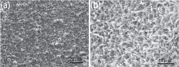
Standard image High-resolution imageThe SEM morphologies of CFO/Cu-foam NWAs and CFO/Cu-foil NWAs after suffer for 100 cycles are shown in figure 10. As shown in figure 10(b), the CFO/Cu-foam NWAs electrode sheet still maintains its 3D network structure after cycling and nanowires are well anchored on the substrate surface as before, which indicating a good structural stability of CFO/Cu-foam NWAs. In contrast, most of the active substances on the CFO/Cu foil-NWAs electrode sheet have fallen off, as shown in figure 10(a), which lead to bad cycle stability and rate capability of the electrodes.
Figure 10. The SEM images of the sample after cycling 100 cycles at 1.0 A g−1 (a) CFO/Cu-foil NWAs, (b) CFO/Cu-foam NWAs.
Download figure:
Standard image High-resolution image
4. Conclusions
The CFO/Cu-foam NWAs integrated electrode was successfully prepared by hydrothermal reaction and subsequent annealing. The CFO NWAs is firmly attached to the substrate even after suffering from 100 cycles at 1.0 A g−1. Electrochemical test results show that the specific capacity and cycling performance of CFO/Cu-foam NWAs integrated electrode are well above those of CFO NWAs electrode prepared by coating process and CFO/Cu-foil NWAs integrated electrode. It is worth noting that this special design strategy is feasible and scalable, which can be extended to grow many other TMO nanostructures on copper foam substrates to produce high power density LIBs.
Data availability statement
The data generated and/or analysed during the current study are not publicly available for legal/ethical reasons but are available from the corresponding author on reasonable request.