
Abstract
The cavitation erosion behavior of Ni foam/polyurethane (PU) co-continuous composites under different experimental conditions was investigated using an ultrasonic vibration cavitation erosion device. Experimental results showed that the Ni foam metal skeleton structure had severe effects on the cavitation resistance of the composites. The composites with thick metal arris and large pore size exhibited good resistance to cavitation erosion. Stress waves had greater influence on the cavitation erosion behavior of composites than micro-jets. In a synergistic way of buffering stress wave in the resin phase and absorbing stress waves in the metal phase, the composites could exhibit better cavitation resistance than pure PU.
Export citation and abstract BibTeX RIS

Original content from this work may be used under the terms of the Creative Commons Attribution 4.0 licence. Any further distribution of this work must maintain attribution to the author(s) and the title of the work, journal citation and DOI.
1. Introduction
Cavitation erosion refers to the generation and collapse of bubbles due to the local pressure change in the liquid medium and the formation of micro-jets that damage the material. It is commonly found in industrial parts, such as turbines, pumps, marine propellers, and valves. Cavitation erosion causes enormous damage to materials, extensively reduces the service life of these industrial parts, decreases industrial production efficiency, increases energy consumption, and brings hidden safety hazards. A series of studies was carried out to reveal the essence of the physical phenomenon of cavitation erosion [1–7]. The occurrence of cavitation erosion was reduced by changing the flow state and flow field of the liquid flow, but the occurrence of cavitation erosion is unavoidable on many occasions, thus putting forward requirements for anti-cavitation materials. At first, high-hardness materials were chosen to resist cavitation erosion. However, in many cases, these materials were relatively brittle. Cracks caused the material to fail under repeated impacts due to the collapse of a large number of bubbles. Materials with high strength, high toughness, high fatigue strength, and good dynamic mechanical properties often have good cavitation erosion resistance [8]. Meeting these requirements is difficult for a single material. In the present study, Ni foam/polyurethane (PU) co-continuous composites were prepared and expected to exhibit good anti-cavitation performance.
PU elastomer is a kind of polymer material with good elastic deformation ability, damping vibration reduction performance, and corrosion resistance. When cavitation erosion occurs, PU undergoes elastic deformation, which could absorb and transfer energy well. In sandblasting and jet experiments, the modified PU and the PU-containing composites showed good anti-erosion performance [9–12]. When the PU was three-dimensionally reinforced by a Ni foam metal skeleton, the metal phase and the resin phase presented continuous and network interpenetrating structure in space. Ni foam/PU co-continuous composites could show good mechanical properties and service performance because of their unique structure. In the present paper, the effects of the pore size and volume density of Ni foam on the cavitation erosion properties of composites were investigated using cavitation erosion tests.
2. Experimental
2.1. Material preparation
A series of Ni foam/PU co-continuous composites with different specifications was prepared by vacuum feeding; the preparation was described in detail in the previous work [13]. Figure 1(a) shows morphology of Ni foam 50PPI 0.5, and figure 1(b) shows morphology of composite 50PPI 0.5/PU. The different co-continuous composites were named after their Ni foam specifications and PU. The prepared Ni foam/PU co-continuous composites were filled completely with few holes. The metal phase and resin phase formed unique interpenetrating network structure.

Figure 1. (a) Morphology of Ni foam 50PPI 0.5, (b) Morphology of composite 50PPI 0.5/PU.
Download figure:
Standard image High-resolution image2.2. Cavitation erosion test
Cavitation erosion test was carried out using piezoelectric ceramic devices in accordance with the ASTM G23 standard, as shown in figure 2. The experiment was conducted in a double-walled stainless-steel container filled with distilled water, with cooling water flowing through it. The amplitude-change pole was used for axial vibration with a frequency of 20 kHz and a maximum amplitude of 60 um. The maximum power of the device was 600 W. The diameter of the vibrating head was 16 mm, and the distance to the experimental sample was 0.5 mm. The sample and the vibrating head were immersed in distilled water. The sample size was 20 mm in diameter and 10 mm in thickness. Before the experiment, each sample was ground to 1000# sandpaper. Different times and powers were chosen for conducting the cavitation erosion experiment on the samples. Each sample was cleaned ultrasonically with distilled water before and after the test, dried to a constant weight in a vacuum environment of 80 °C, and weighed using an analytical balance with an accuracy of 0.1 mg. A mass loss was obtained. Each test was repeated three times for reproducibility. The morphology of the sample after cavitation erosion test was observed using a wide-area 3D measurement system (VR-3200, Keyence, Japan) and a scanning electron microscope (Inspect F50, FEI Co., USA).
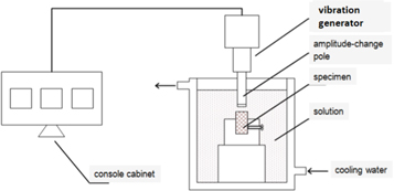
Figure 2. Schematic of the vibration cavitation erosion apparatus.
Download figure:
Standard image High-resolution image3. Results and discussion
3.1. Behavior of material cavitation erosion damage
Considering that the density of different experimental materials differs, in this study, the measured mass loss was divided by the respective density to obtain the volume loss and judge the amount of cavitation erosion damage. The experimental results are shown in figure 3. Under the condition of 50% power for 20 min, the smaller the pore size of the composite, the greater the volume loss obtained. When the pore size was the same, the larger the volume density of the Ni foam, the smaller the volume loss of the corresponding composite. The volume loss of pure PU was greater than that of the composite 25PPI 1.7/PU, which was superior to other composites. The volume loss of all materials was much greater under the condition of 100% power for 20 min than under 50% power for 20 min, because the frequency of the cavitation erosion equipment was not variable. When the power was changed, the amplitude of the amplitude-change pole of the equipment changed, and the power was proportional to the square of the amplitude. In the study of B. Vyas and C. M. Preece [14], at 20 kHz, when the amplitude of the amplitude-change pole was in the range of 20–140 um, the number of bubbles reaching the critical nuclear radius increased and the cavitation effect became more intense as the amplitude increased. The experimental results in the present study showed that the volume loss of 50PPI 1.3/PU increased the most at 536%, whereas that of 50PPI 0.5/PU increased the least at 56%. The volume loss of 25PPI composites and 50PPI 0.5/PU was less than that of pure PU, whereas the volume loss of other composites was much greater than that of pure PU. Under the condition of 100% power for 60 min, the volume loss of different materials has increased to different degrees compared with that under the condition of 100% power for 20 min. The volume loss of composite 100PPI 0.8/PU increased by 239%, while the growth rate of volume loss of other composites and pure PU was less than 75%. Among them, the volume loss of 100PPI 0.8/PU and 50PPI 1.3/PU was much larger than that of pure PU, and the volume loss of other composites was smaller than that of pure PU. The cavitation erosion damage of 25PPI 1.7/PU was minimal. In general, the composites showed enhanced cavitation erosion resistance with the increase in power and time compared with pure PU.
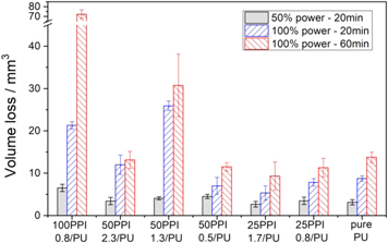
Figure 3. Cavitation erosion volume loss of pure PU and composites under different powers at different durations.
Download figure:
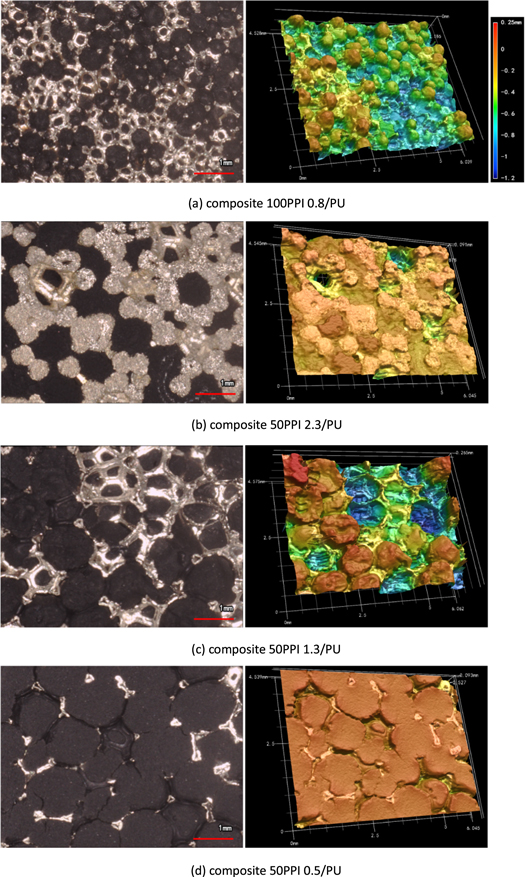
Standard image High-resolution imageFigure 4 shows the morphologies of the cavitation erosion damage in the samples under the condition of 100% power for 60 min. The morphologies of composite damage can be divided into three types. In the first type, a large number of resin phases were detached from the metal arris, and the metal arris was severely damaged, showing an uneven surface, as shown in figures 4(a) and (c). In the second type, a small piece of resin phase peeled off from the surface of the material and the metal arris damage was small, showing a rough surface, as shown in figures 4(b), (e), and (f). In the third type, the peeling of metal arris fracture and the resin damage were lessened, showing a flat surface, as shown in figure 4(d). Composites with small pore size and small volume density are prone to the first type of damage, while those with large pore size and large volume density are prone to the second type of damage. Pure PU has two large cavitation craters and many small cavitation pits accompanied by long and deep cracks.
Download figure:
Standard image High-resolution image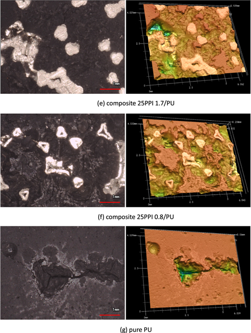
Figure 4. Morphologies of samples after cavitation erosion test under 100% power for 60 min.
Download figure:
Standard image High-resolution imageFigure 5 shows the change in the amount of cavitation erosion damage with time of 100PPI 0.8/PU, 50PPI 0.5/PU, and pure PU. The slope of the broken line indicated the cavitation damage rate of the material. The cavitation damage rate of 100PPI 0.8/PU increased and it did not change after 5 min, while that of 50PPI 0.5/PU also started to increase but decreased considerably and did not change after 5 min. The cavitation damage rate of pure PU increased and then decreased. After 20 min, this rate remained the same as that of 50PPI 0.5/PU.
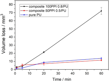
Figure 5. Change in the amount of cavitation erosion damage with time under 100% power.
Download figure:
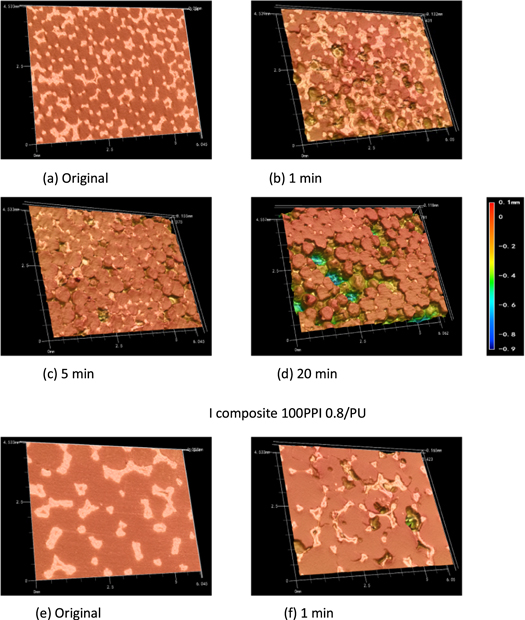
Standard image High-resolution imageFigure 6 shows the cavitation morphology of the above three materials after different test times. For 100PPI 0.8/PU, the resin phase peeled off from the metal arris after 1 min, the metal arris peeled off from the sample surface after 5 min, and both peeled off alternately after 20 min. Therefore, the cavitation damage rate remained unchanged. For 50PPI 0.5/PU, from 1 min to 60 min, the material damage was mainly the peeling off of the surface metal arris, and no peeling was observed in the bulk resin phase. Thus, the cavitation damage rate decreased. For pure PU, cavitation craters on the millimeter scale were formed in 1 min. With time, the number of cavitation craters did not increase, but the craters further developed into enlarged and deepened cavitation craters, accompanied by deepened and lengthened cracks. In addition, ring cracks were observed on the surface of the sample, and spot pits were found around these ring cracks.
Download figure:
Standard image High-resolution image
Figure 6. Morphologies of the samples after cavitation erosion test under 100% power for different durations.
Download figure:
Standard image High-resolution imageThe structure of Ni foam considerably influences the cavitation damage in the composite. The Ni foam has a similar regular dodecahedral structure [15]. Each metal arris is a hollow triangular prism structure. Table 1 shows the metal arris thickness and specific surface area of different Ni foams. The Ni foam/PU co-continuous composite could be considered to be composed of a number of regular dodecahedral units. Each unit was composed of 12 pentagonal metal arris wrapped with PU, and the interface between the units was a resin phase surrounded by pentagonal metal arris.
Table 1. Structure parameters of different Ni foams.
| Ni foam | Metal arris thickness μm | Specific surface area 103 m−1 |
|---|---|---|
| 100PPI 0.8 | 21 | 7.55 |
| 50PPI 2.3 | 102 | 4.02 |
| 50PPI 1.3 | 59 | 3.67 |
| 50PPI 0.5 | 30 | 3.45 |
| 25PPI 1.7 | 125 | 1.86 |
| 25PPI 0.8 | 87 | 1.43 |
The above experimental results revealed that under cavitation, the thin metal arris (≤59 μm) showed obvious plastic deformation and fracture peeling. Even if it were in the subsurface, it could still break and flake, as shown in figure 7(a). The thick metal arris (≥87 μm) only exhibited a plastic flow on the surface and some small cutting phenomena, as shown in figure 7(c). For 50PPI 1.3/PU, the resin phase was detached from the metal arris. Figure 7(b) illustrates that the sample surface showed metal phase and resin phase peeling. The right-side metal arris in unit 1 was detached, the left side was de-bonded from the metal arris, and the protection of the metal arris was lost. Cracks appeared at the interface between unit 1 and unit 2. As the test progressed, the resin phase in unit 1 was removed from the metal arris gridding.
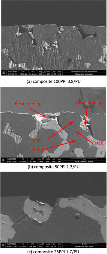
Figure 7. Sectional morphology after cavitation erosion test under 100% power for 20 min.
Download figure:
Standard image High-resolution image3.2. Material damage mechanism
3.2.1. PU damage
Cavitation erosion is due to the collapse of bubbles near the surface of the material, resulting in micro-jets that damage the material. When a bubble collapses asymmetrically a micro-jet is formed, and its velocity could reach hundreds of meters per second [1, 16]. The formula for calculating the pressure on the basis of water hammer is [17]

Where c is the speed of sound in the liquid, ρ is the liquid density, and v is the flow velocity. The instantaneous pressure of the jet with hundreds of meters per second hitting a solid surface could reach hundreds of MPa. Some scholars even believed that the water hammer action could reach a pressure of several GPa, which is enough to cause plastic deformation or fracture in most materials [18, 19].
There are many types of PU. The PU elastomer used by the authors has slight plastic deformation ability [13]. Under the effect of micro-jets, the resin had almost no plastic flow, and it directly generated cracks and fractures. The surface showed spot pits. As shown in figure 8(a), spot pits of different sizes were found on the surface, and these spot pits could converge into a larger crater. Given the small size of the micro-jet, the effect of the lateral jet and hydraulic penetration of the liquid flow was not obvious, and it could be combined with the water hammer action.
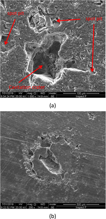
Figure 8. Pure PU surface morphology after cavitation erosion test under 50% power for 20 min.
Download figure:
Standard image High-resolution imageHigh-speed micro-jets hit solid surfaces, not only causing spot pits but also generating stress waves. According to elastic half-space theory, collisions produce three different types of waves: compression waves, shear waves, and Rayleigh waves. Compression and shear waves take the collision point as the starting point and propagate radially into the solid, but the wave speeds of the two are different. Rayleigh waves only propagate on the surface, with the slowest wave speed and an elliptical trajectory [20]. Compression, shear, and Rayleigh waves occupy 7%, 26%, and 67% energies, respectively [21].
Some brittle materials produce ring cracks under the impact of high-speed liquid flow, which is caused by Rayleigh waves [22, 23]. The ring cracks on figures 6(j) and (k) were probably also formed by Rayleigh waves (interfacial waves). When a ring crack was generated, the resin on both sides of the crack showed a new boundary. The boundary effect increasing the chance of micro-jets resulted in more spot pits found near the ring cracks than other positions, which also promoted the formation and development of cavitation crater. With the passage of time, the resin inside the ring cracks continuously peeled off, as shown in figure 8(b).
During the propagation of stress waves, when stress waves encounter material defects, cracks arise and crack propagation is accelerated. This phenomenon causes damage to the subsurface layer of the material [24, 25]. The crack at the bottom of the spot pit spreads into the material under the action of the stress wave, and the convergence of multiple cracks causes the resin to flake off and accelerate the formation of cavitation craters. Figure 9 shows a large piece of resin (middle of the picture) that was about to peel off due to the convergence of multiple cracks. Under the action of micro-jets and stress waves, the surface of the PU first formed ring cracks. The ring cracks promoted the formation of spot pits, which accelerated the initiation, expansion, and convergence of cracks. Eventually, a large cavitation crater was formed.
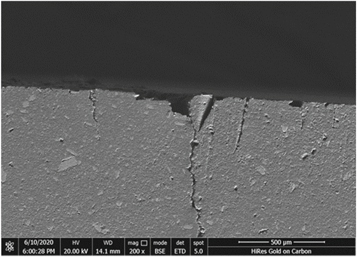
Figure 9. Pure PU sectional morphology after cavitation erosion test under 100% power for 20 min.
Download figure:
Standard image High-resolution image3.2.2. Composite damage
Under the effect of cavitation erosion, the composites were affected by micro-jets and stress waves. The micro-jets caused spot pits in the resin phase and plastic deformation and fracture in the metal phase on the material surface. The effect of stress waves was more significant. Thus, the composites with different structures exhibited varying cavitation erosion behavior.
According to the wave theory, when the wave propagates in the medium, the ratio of the pressure acting on an area to the mass flow rate passing through the area per unit time indicates resistance, called wave impedance. Its value is equal to the product of medium density ρ and wave velocity v. The propagation speed of stress waves depends entirely on the elastic and inertial properties of the medium itself, that is, the elastic modulus and density of the medium. Wave impedance (Z) in one dimension is calculated as follows [26]:

Therefore, the larger the density ρ and the elastic modulus E, the larger the wave impedance is. The causes of stress wave attenuation during propagation mainly include physical factors and geometric factors. The physical factors are mainly caused by the incomplete elasticity of the medium, also known as inherent attenuation. The result of its function is to convert a part of the energy into heat dissipate. The geometric factors are mainly due to the expansion of the wave front and the reflection and refraction of the stress waves on the structural surface, which all cause the change in the vibration amplitude. The result of its action is change in the distribution of the stress wave energy in space [27].
The density and elastic modulus of pure PU were much smaller than those of metallic Ni; thus, pure PU exhibited smaller wave impedance. The PU wave impedance was small. Therefore, PU could transfer most of the stress wave energies and dissipate them in the form of heat, which is beneficial to its anti-cavitation performance.
When the stress wave propagates in the metal edge, it quickly decays, and most of the energies of the stress wave is converted into the plastic deformation work of the metal arris. When the stress wave plastically deforms the metal arris, it may also cause the metal arris to break. The research of Chen Haosheng [28] showed that under cavitation erosion, high-speed micro-jets not only plastically deformed the surface of the material but also caused crystal cracks and comminution in the subsurface layer of the material under the action of shear waves. As shown in figure 7(a), the metal arris in the subsurface layer broke and flaked. This finding could be attributed to the fact that stress waves pass through the resin phase of the surface. When a large stress concentration occurs at a specific position of the thin metal arris, the metal arris breaks and peels off. Thick metal arris could well absorb the energy of stress waves, and cracks are difficult to penetrate through, whereas the opposite is true for thin arris.
The wave impedance of Ni foam/PU co-continuous composite was higher than that of pure PU. When cavitation erosion occurred, the resin phase in the composite could transfer a part of the energy of the stress wave, and the remaining energy was converted into internal energy, resin deformation work and fracture work, metal arris deformation work and fracture work, and the fracture work of the two-phase interface.
Stress waves exhibit inherent attenuation in homogeneous materials, and their propagation in composites is closely related to their geometrical structure factors. Figure 10 shows a schematic of two-dimensional propagation of stress waves in Ni foam/PU co-continuous composites. When the stress wave meet the two-phase interface, reflection and refraction occur. When these stress waves meet, and increase or decrease in the interface could occur at a specific position. Even if the initial stress wave amplitude is small, several reflected stress waves may be superimposed together to generate enough stress to rupture the material.
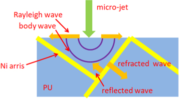
Figure 10. Two-dimensional diagram of stress wave damage mechanism of composites.
Download figure:
Standard image High-resolution imageAlthough the wave impedance of the resin phase was very small, the stress or particle velocity of the spherical wave front was still geometrically attenuated at a ratio of 1/r, where r is the distance from the disturbance source. When the stress wave in the resin met the metal phase, a part of the stress wave energy was brought back by the reflected wave, and a part of the stress wave energy was transmitted to the metal arris by the refraction wave. An interface wave also occurred at the interface of the two phases. Therefore, the two-phase interface became a region where the stress wave energy was concentrated. Table 1 shows the specific surface area of different Ni foams. The specific surface area of Ni foam corresponded to the area of the two-phase interface of the composites. The smaller the pore size, the more the two-phase interface of the composite material had. When the pore size is the same, the larger the volume density of the Ni foam, the more the two-phase interface of the composite.
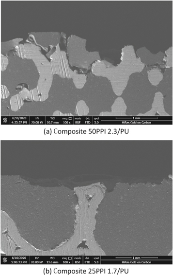
When the pore size was small (100, 50PPI), the stress wave in the resin phase exhibited a short geometric attenuation path, and a large amount of energy was enriched at the interface of the two phases, resulting in interface debonding; the resin phase was also peeled off from the metal arris, as shown in figure 11(a). When the pore size was large (25PPI), the stress wave in the resin phase showed a long attenuation path. Given the geometric and physical attenuations, even if multiple reflected waves met and interfered with each other, the energy generated was not enough to cause resin phase cracking and interface debonding. Moreover, a part of the stress wave in the resin phase as absorbed by the metal arris, thereby alleviating the stress wave energy concentration in the sub-surface layer of the resin phase, and no long cracks appeared in the resin phase, as shown in figure 11(b). This finding showed that the composites with large pore size could effectively suppress the energy concentration of stress waves inside the material and effectively reduce the crack initiation and propagation of the subsurface layer of the material.
Figure 11. Sectional morphology after cavitation erosion test under 100% power for 20 min.
Download figure:
Standard image High-resolution image
As the thin metal arris was the first to rupture and peel under the action of cavitation erosion, the surface of 50PPI 0.5/PU was dominated by resin phase, as shown in figures 6(f)–(h). The surface of the resin phase was free from the restraint of the metal skeleton, and it could exhibit greater elastic deformation and withstand the impact of micro-jets in the manner of elastic deformation. After the metal arris broke and peeled off, the surface of the composite was mainly resin phase, the wave impedance became smaller, and the ability to transmit stress waves strengthened. The water in the cavitation crater absorbed a part of the energy of the stress wave in the form of refracted waves. Given that water is incompressible, it showed no resistance to tensile and shear. The resin at the crater boundary must overcome the resistance of water to work when vibrated by the stress wave. In summary, although 50PPI 0.5/PU showed smaller pore size and thinner metal arris than 25PPI, it could also exhibit the same good anti-cavitation performance. The obtained results demonstrated that making a suitable texture on the surface of the material is conducive to improving the anti-cavitation performance.
On the conditions of 100% power for 20 min and 100% power for 60 min, 25PPI showed less cavitation damage than pure PU. As the composite with large aperture showed a long geometric attenuation path for the stress wave, its less two-phase interface reduced the stress wave reflection and the local energy concentration of the stress waves. The presence of metal arris could absorb the energy of the stress waves in the form of plastic deformation and fracture and block the interference between the stress waves. In a synergistic way of buffering stress waves in the resin phase and absorbing stress waves in the metal phase, the composite could exhibit more excellent cavitation resistance than pure PU.
4. Conclusion
- (1)The Ni foam metal skeleton structure had severe impacts on the amount of cavitation damage in the composites. As the pore size and metal arris thickness of the Ni foam increased, this amount decreased. Under high-power and prolonged test conditions, the composites exhibited better cavitation resistance than pure PU.
- (2)The Ni foam metal skeleton structure also had severe impacts on the cavitation damage morphologies of the composites. Composites with small pore size and small volume density appeared alternate fracture and peeling of the resin phase and the metal phase. Those with large pore size and large volume density only had plastic deformation of a small amount of metal phase and peeling off of a small amount of resin phase on the surface.
- (3)Pure PU had large cavitation crater and many small spot pits accompanied by long and deep cracks, and its cavitation damage was mainly controlled by the micro-jet mechanism.
- (4)The cavitation damage of the composites was controlled by the micro-jet mechanism and the stress wave mechanism, and the effect of the stress wave was more obvious. The composites with large pore size and large volume density exhibited a long geometric attenuation path to the stress wave. Their less two-phase interface reduced the stress wave reflection and the local energy concentration of the stress waves. The presence of metal arris could absorb the energy of the stress wave in the form of plastic deformation and fracture and then block the interference between the stress waves. In a synergistic way of buffering stress waves in the resin phase and absorbing stress waves in the metal phase, the composites could exhibit more excellent cavitation resistance than pure PU.
Acknowledgments
This project was supported by the National Natural Science Foundation of China (No. 51275506), National Youth Science Foundation of China (No. 51801207) and the Shenyang Key Laboratory of Aero-engine Materials Tribology (SKLAMT201903).
Data availability statement
All data that support the findings of this study are included within the article (and any supplementary files).