

Abstract
In order to improve the marine corrosion resistance of the copper alloy, the method of synergistic modification was introduced to prepare the in situ coating on the surface of HSn62-1 by laser shock melt injection of fine-CeO2 particles. The micrograph and microstructure of the Hsn62-1, in situ coating, and the laser-treated sample were investigated in contrast. Besides, the electrochemical corrosion resistance of the three specimens in 3.5% NaCl solution was studied. The results demonstrated that the in situ coating had good compactness and no apparent defects. The upper part of the in-suit coating was mainly cellular solidification microstructure, while the microstructure in the middle and lower part was coarse dendrite. Compared with Hsn62-1 copper alloy, the corrosion resistance of the laser-treated sample and the in-suit coating were improved, which proved that the synergistic modification of laser and rare earth could improve the corrosion resistance of the copper alloy. The analysis indicated that the rare earth elements in the in-suit coating would undergo hydrolysis reaction to form the dense rare-earth hydroxide in an 'island growth' way, which effectively prevented the invasion of corrosion ions.
Export citation and abstract BibTeX RIS

Original content from this work may be used under the terms of the Creative Commons Attribution 4.0 licence. Any further distribution of this work must maintain attribution to the author(s) and the title of the work, journal citation and DOI.
1. Introduction
The copper alloy has excellent characteristics such as high strength, good corrosion resistance, and secure processing and forming [1]. It is widely used in the manufacture of essential equipment parts in fields of marine transportation, ocean exploration, and deep-sea mining [2]. However, natural seawater contains extremely corrosive chloride salts, which inevitably harm the service life and safety of copper alloys. Besides, with the deteriorating marine environment, the demand for materials with high corrosion resistance continues to rise, and the seawater corrosion problem of copper alloys has become more prominent. It is of considerable significance to carry out relevant research on the seawater corrosion resistance of copper alloys.
Rare earth is known as 'industrial gold', which can significantly improve the alloy's quality and properties, such as anti-spalling performance, high-temperature oxidation resistance, and corrosion resistance [3–5]. Many studies showed that adding rare earth elements to copper alloys could increase the uniformity and compactness of the passivation film and its film resistance, thereby improving its corrosion resistance [6, 7]. Besides, preparing the protective coating is another effective method to improve the corrosion resistance of copper alloy, which can prevent corrosion medium from invading the copper alloy matrix. At present, the coating preparation technologies include electroplating, thermal spraying, chemical vapor deposition(CVD), and laser surface modification [8–10]. However, compared with the traditional coating preparation technologies, the laser surface modification has unique advantages in optimizing coating structure, coating composition, and thickness control [11–13], which has great application potential in anti-corrosive coatings [14, 15].
In the previous research, we proposed a new method in preparing the in situ coating called fine-particle laser shock melt injection [16]. The method develops the laser to induce binders to form a plasma shock wave, which provides the injection force for particles. Figure 1 presents the schematic diagram of the laser shock injection process. If using the method to introduce the rare earth to the copper alloy, the synergistic strengthening effect of laser modification, coating protection, and rare earth effect would further improve the copper alloy's corrosion resistance.
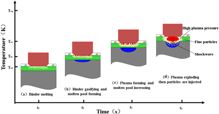
Figure 1. Schematic of laser shock injection process.
Download figure:
Standard image High-resolution imageIn this study, the method of synergistic modification was introduced to prepare the in situ coating on the surface of HSn62-1 by laser shock melt injection of fine-CeO2 particles. The micrograph and microstructure of the Hsn62-1, in situ coating, and the laser-treated sample were investigated in contrast. The electrochemical corrosion resistance of the three specimens in 3.5% NaCl solution was studied. Besides, the formation mechanism of the passive film on the surface of the in situ coating was discussed.
2. Materials and methods
2.1. Materials
HSn62-1 copper alloy with low temperature annealing (350 ℃ ∼ 370 ℃) was used as the substrate. The nominal composition of the substrate was Cu61.4, Zn37.6, Sn0.9, Fe0.04 and Pb0.007 [16]. Fine-CeO2 with a size of 1 μm were used as injected particles. Also, pure analytical ZnCl2 was used as the binder. Quartz glass was utilized as the confining medium with dimensions of 12 mm length, 2 mm thickness and 11 mm width.
2.2. Sample preparation
The three copper alloy specimens with dimensions of 10 mm × 10 mm × 5 mm were obtained using wire-electrode cutting, and one of the specimen surfaces was ground by using 400 grit sandpaper, followed by cleaning with absolute ethanol. Subsequently, 50 ml absolute ethanol, 50 ml deionized water, 20 g CeO2 powder and 5 g ZnCl2 were mixed to prepare the fine-CeO2 slurry, and the ultrasonic dispersion was carried out for 15 min. Afterwards, the surface of the specimens was brushed with the slurry for 3–5 times and dried using the electrical heating device, as shown in figure 2. Finally, the surface of the specimens was covered with quartz glass.
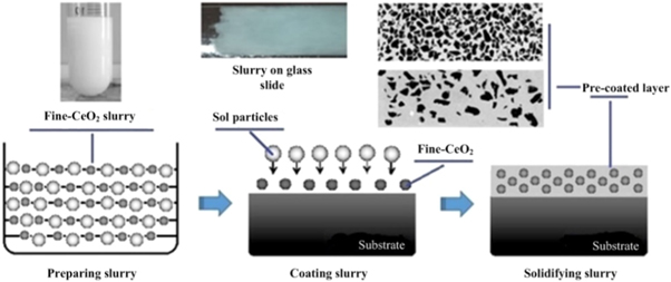
Figure 2. Diagram of slurry preparation and coating process.
Download figure:
Standard image High-resolution image2.3. Laser shock melt injection
The single-channel laser shock injection test was carried out using ZKSX-3008 fiber-optic coupled all-solid-state laser processing systems. High purity argon was used as the shielding gas with a flow rate of 10 l · min-1, as shown in figure 3. Based on the orthogonal experiment, the laser power is 1200 W, the scanning speed is 950 mm · min-1, and the spot diameter is 3 mm. Besides, in the test, the three specimens are treated in different processing conditions as shown in table 1.
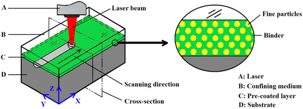
Figure 3. Schematic of laser shock melt injection.
Download figure:
Standard image High-resolution imageTable 1. The processing conditions of samples.
| Samples | Processing condition | Purpose |
|---|---|---|
| a | original sample | control group |
| b | laser treatment without CeO2 | control group |
| c | laser treatment with CeO2 | experimental group |
2.4. Testing and analysis
- (1)Microscopic characterizationThe metallographic specimens were prepared from the same samples at three different positions perpendicular to the laser scanning direction. The specimens were chemically etched in a solution containing FeCl3, HCl and H2O in a volume ratio of 1:2:5 for approximately 20 s. The morphology, microstructure and composition of coatings were observed by using the EDS spectrometer equipped with Zeiss Merlin compact scanning electron microscope.
- (2)Electrochemical characterization
The electrochemical test was carried out on the PRA2273 electrochemical workstation. The three-electrode system was used. The experimental sample was a working electrode. The saturated calomel electrode and plugin capillary with a salt bridge were used as a reference electrode. The platinum electrode was used as an auxiliary electrode. The corrosion solution was 3.5% NaCl solution. The polarization curve's scanning range was ± 800 mV, and the scanning rate was 0.8 mv s−1.
3. Results and analysis
3.1. Morphology of the in-suit coating
Figure 4 shows the morphology of the in-suit coating after laser shock melt injection of fine-CeO2 particles. The whole coating is crescent-shaped, and its upper surface is concave with local pits. Besides, the content of Ce in the molten pool is as high as 1.15%. It was believed that due to the difference in thermal properties between coating material and substrate, the standard preset laser modification technology inevitably causes defects such as holes and cracks in coatings [17, 18]. However, it can be seen from figure 4 that there are almost no such defects. The analysis shows that when the laser energy acted on the preset layer, the inorganic binder was gasified, which did not introduce impurities, therefore, this method can hardly produce porosity defects. Meanwhile, in the experiment, the considerable laser power value (1200 W) and the small scanning speed (950 mm · min-1) can reduce the temperature gradient of the coating, thus avoiding the trend to form cracks [11].
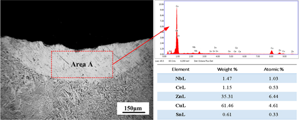
Figure 4. The morphology of the in-suit coating.
Download figure:
Standard image High-resolution image3.2. The microstructure
Figure 5 shows the microstructure of the three samples. Figure 5(a) is HSn62-1; figure 5(b) is the laser-treated sample without fine-CeO2 particles; figure 5(c) the upper part of the in-suit coating, and figure 5(d) is the middle and lower parts of the in-suit coating.
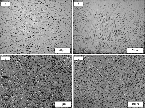
Figure 5. The microstructure of copper alloy and coatings. (a) Hsn62-1 copper alloy; (b) laser-treated sample without fine-CeO2 particles; (c) the upper part of in-suit coating; (d) the middle and lower part of the in-suit coating.
Download figure:
Standard image High-resolution imageThe microstructure of the HSn62-1 is mainly composed of α + β phase [19]. It can be seen from figure 4 that the β phase is a black strip or block, and the α phase exists as a white block. After the laser treatment without fine-CeO2 particles, the α phase is in the shape of an ordered long strip, while the β phase changed to ordered fibrous and finely granular. The analysis shows that laser modification is a process of high temperature and rapid cooling [20]. The directional solidification and 'high temperature and rapid cooling' lead to the microstructure's growth in a particular direction. After adding the Ce, the upper part of the in-suit coating is mainly cellular solidification microstructure with a small amount of white granular compounds dispersing at the grain boundary (figure 5(c)). The EDS analysis shows that it is composed of Cu, Zn, and a small amount of Ce, while the microstructure in the middle and lower part of the in-suit coating is coarse dendrite with the white granular compounds mainly distributing on the surface of the tissue (figure 5(d)). The reason for the changes in the microstructure at different parts of the in-suit is that, on the one hand, cerium-containing compounds are distributed at the grain boundaries, which act as nucleating particles during the solidification of the molten pool and quickly interrupt the orderly growth of the tissue, thereby refining the microstructure of the coating [21]. The plasma shock wave induced by the laser may interrupt the growth of the near-surface microstructure of the coating.
3.3. Electrochemical corrosion
Figure 6 shows the electrochemical polarization curve. Figure 6(a) is HSn62-1; figure 6(b) is the laser-treated sample without fine-CeO2 particles; figure 6(c) is the in-suit coating prepared by laser shock melt injection of fine-CeO2 particles.
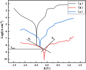
Figure 6. The electrochemical polarization curve. (a) Hsn62-1 copper alloy; (b) laser-treated sample without fine-CeO2 particles; (c) the in-suit coating.
Download figure:
Standard image High-resolution imageThe polarization curve gradually moves to the lower right from (a) to (c), which indicates that the self-corrosion potential positively shifted. Compared with sample (a), the self-corrosion potential of the sample (c) positively shifted by 385.94 mV; however, the self-corrosion potential of sample (b) positively shifted by 220.24 mV. Based on the self-corrosion potential, the degree of corrosion difficulty is (c) > (b) > (a).
Table 2 shows the relevant results of the self-corrosion current density and polarization resistance of electrochemical corrosion. The fitting results are calculated based on the Stern formula [17]:
Table 2. The relevant results.
| Samples |
 (mV) (mV) |


|
 (mV) (mV) |
 (mV) (mV) |


|
|---|---|---|---|---|---|
| a | −495.92 |

| 43.36 | 58.13 |

|
| b | −275.68 |

| 52.64 | 61.35 |

|
| c | −109.98 |

| 38.63 | 59.19 |

|
 is the polarization resistance;
  and
and  are the reciprocal of the slope of the two epitaxial lines of the polarization curve;
  is the self-etching current density.
The self-corrosion current densities of sample (a), (b) and (c) are respectively 
 and
and  The self-corrosion current density reflects the degree of corrosion that the smaller the value, the slower the corrosion rate of the sample in the corrosive medium [22]. The sample (c) presents a lower corrosion rate and the best corrosion resistance.
Figure 7 shows the XRD analysis of the samples after electrochemical corrosion. The surface corrosion products of samples (a) and (b) mainly include Cu2O, CuO, and Cu2(OH)3Cl. However, besides CuO, Cu2O, and Cu2 (OH)3Cl, the corrosion surface of sample (c) also contains Ce (OH)4.
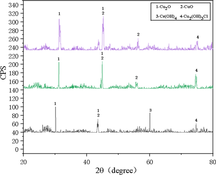
Figure 7. The XRD analysis of surface after electrochemical corrosion. (a) Hsn62-1 copper alloy; (b) laser-treated sample without fine-CeO2 particles; (c) the in-suit coating.
Download figure:
Standard image High-resolution imageFigure 8 shows the surface morphology of samples before and after electrochemical corrosion. Figure 8(a) is HSn62-1 before corrosion; figure 8(b) is HSn62-1 after corrosion; figure 8(c) is the laser-treated sample without CeO2 before corrosion; figure 8(d) is the laser-treated sample without CeO2 after corrosion; figure 8(e) is the in situ coating before corrosion; figure 8(f) is the in situ coating after corrosion.
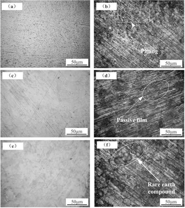
Figure 8. Surface morphology of samples before and after electrochemical corrosion. (a) HSn62-1 before corrosion; (b) HSn62-1 after corrosion; (c) Laser-treated sample without CeO2 before corrosion; (d) Laser-treated sample without CeO2 after corrosion; (e) In-situ coating before corrosion; (f) In-situ coating after corrosion.
Download figure:
Standard image High-resolution imageThe surface of the laser-treated sample without CeO2 and the in situ coating show good compactness. After electrochemical corrosion, the protective passivation film on the surface of HSn62-1 seriously exfoliates, and there were local corrosion pits, which is mainly caused by the damage of Cl-. In the process of forming a passivation film on copper alloy, it is impossible to keep the uniformity of passivation film, which result in different adsorption of Cl- on the passive film and local corrosion spots. Although the laser-treated sample's passive film partially detached after corrosion, no noticeable corrosion pits exist, as shown in figure 8(d). The analysis shows that the laser treatment can effectively control and optimize the original matrix structure, which is conducive to improve the structure density and the uniformity of the structure composition, thus forming a dense and uniform passivation film. From figure 8(f), there are no pitting pits on the surface of the in situ coating after corrosion. However, many 'island-like' corrosion products appeared on the surface, which tended to be interconnected. Studies showed that during the corrosion process, the rare earth cations tended to form dense rare-earth hydroxide on the alloy surface in the way of 'island growth,' which gradually formed a thin film covering the surface of the alloy through a mutual connection [23, 24]. According to figure 7, it can be inferred that those mentioned above rare earth-containing island compound is Ce(OH)4, which isolates the corrosive medium from contacting the Cu2O and CuO passivation film and plays a role in protecting the passivation film.
4. The formation mechanism of passivation film
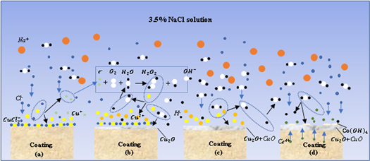
The corrosion behavior of copper alloy in seawater is the same as the pitting corrosion mechanism of passivated metal in Cl− solution. The local damage of corrosion-resistant passivation film on the surface of copper alloy caused by Cl−, which results in stress corrosion, pitting corrosion, crevice corrosion, and hydrogen embrittlement. Therefore, the passive film's stability is the critical factor in determining the copper alloy's corrosion resistance. The formation of a passivation film on in-suit coating prepared by laser shock melt injection of fine-CeO2 particles in NaCl solution consists of four parts.
Firstly, Cu reacts with Cl- in corrosive medium to form cuprous dichloride complex in anode region [25], as shown in figure 9(a).

Figure 9. Formation mechanism of passive film on in-suit coating.
Download figure:
Standard image High-resolution image
Secondly, the partially dissolved O2 in the corrosion medium reacts with water to form a small amount of strong oxidizing H2O2, which oxidizes Cu+ to Cu2+ [26], as shown in figure 9(b)


Then, Cu+ and Cu2+ are hydrolyzed to form dense CuO + Cu2O composite passive film [27], as shown in figure 9(c).


In the process of forming a stable passive film, Cl- in the corrosion medium will continue to erode the defects or loose parts of the passive film. At this time, the rare earth elements in the in-suit coating will also undergo hydrolysis reaction to form the dense rare-earth hydroxide, which grows in an 'island growth' way, and gradually covers the surface of the passive film, which can effectively prevent the invasion of corrosion ions, as shown in figure 9(d). The explanation of precipitation mechanism of rare earth oxides and hydroxides is based on the hydrolysis reaction of rare earth cations proposed by Baes and Mesmer [28]:

Therefore, the hydrolysis reaction of Ce4+ in corrosive medium can be written as:

The corrosion resistance of the in-suit coating and the laser-treated sample is higher than that of the original copper alloy. The main reasons for the increased corrosion resistance are the improvement of the matrix tissue by laser modification and the dense rare-earth hydroxide protective film, proving that the synergistic modification of laser and rare earth can improve the corrosion resistance of the copper alloy.
5. Conclusion
In this study, the method of synergistic modification was introduced to prepare the in situ coating on the surface of HSn62-1 by laser shock melt injection of fine-CeO2 particles. The micrograph and microstructure of the Hsn62-1, in situ coating, and the laser-treated sample were investigated in contrast. The electrochemical corrosion resistance of the three specimens in 3.5% NaCl solution was studied. Besides, the formation mechanism of the passive film on the surface of the in situ coating was discussed. The results of the study were summarized as follows:
- (1)The in-suit coating prepared by laser shock melt injection of fine-CeO2 particles had good compactness and no apparent defects. Its upper part was mainly cellular solidification microstructure, but its middle and lower parts are mostly coarse dendritic microstructure.
- (2)Compared with the original copper alloy, both the in-suit coating and the laser-treated specimen showed excellent corrosion resistance. The in-suit coating had high self-corrosion potential, low self-corrosion current density, and significant electrochemical capacitance resistance, which proved that the synergistic modification of laser and rare earth could improve the corrosion resistance of the copper alloy.
- (3)The rare earth cations tended to form dense rare-earth hydroxide on the copper alloy surface, which isolated the corrosive medium from contacting the Cu2O and CuO passivation film and played a role protecting the passivation film.
Acknowledgments
This work was supported by the Colleges and Universities Graduate Innovation Practice Program of Jiangsu Province [Grant number SJLX16_0439], and the National Natural Science Foundation of China [Grant number 51372216].