
Abstract
This paper was to research the effects of surface rolling at low-heating temperatures (SRLT) on microstructure and mechanical properties of HIP Ti–6Al–4V alloy. An obviously plastic deformation emerged in surface modification layer and accompanied with the grain refinement and dense dislocations. The values of compressive residual stress and surface microhardness were also increased. The fretting friction tests were further compared without lubrication. The sample treated by surface rolling (SR) at 160 °C had the smaller steady-state CoF and less material loss relative to the untreated sample. But it still had the higher steady-state Coefficient of friction (CoF) and more material loss than surface-rolled sample at room temperature. On the one hand, the comparatively low microhardness and residual stress would damage the mechanical properties. On the other hand, the material's friction would be increased by the high surface roughness and the absence of cold work strengthening would decrease the wear resistance. In addition, the low-heating temperature would also increase material deformation mechanism and decline the friction properties.
Export citation and abstract BibTeX RIS

Original content from this work may be used under the terms of the Creative Commons Attribution 4.0 licence. Any further distribution of this work must maintain attribution to the author(s) and the title of the work, journal citation and DOI.
1. Introduction
With the development of industry technology, the higher and higher requirements are placed on the performance of materials. As one of the structural high-performance titanium alloys, Ti-6Al-4V alloy has been widely used in various engineering fields. The outstanding properties of Ti-6Al-4V alloy include the superior strength-to-weight ratios, good toughness and fatigue strength, excellent corrosion resistance and so on [1–3]. Ti-6Al-4V alloy manufactured by hot isostatic pressing (HIP) also has these good properties and can avoid the composition segregation defects and uneven porosity inside the material caused by casting process. Moreover the forged titanium alloy can be replaced by HIP Ti-6Al-4V alloy in some practical application cases [4, 5], and the actual application performance is also very good [6, 7]. In addition, HIP process has the advantage to produce titanium alloy components with the complex shape and has the uniform density [8]. However the poor friction performance of Ti-6Al-4V alloy greatly limits its use scope due to the susceptibility to failure by the galling and unstable friction Coefficient when rubbing against common bearing materials [9]. The fatigue failure process of the components manufactured by titanium alloy will be accelerated by the crack initiation sites which are produced in material surface by fretting wear [10]. So some methods have been done to improve surface and friction properties of Ti-6Al-4V alloy, which mainly includes cold surface rolling, SMAT, ultrasonic surface rolling and so on. Wang et al [11] have studied the effect of process duration on the microstructures of fast multiple rotation rolling-induced nanocrystalline layer and its wear properties. The results indicated that the size of nanocrystallites could be as small as 50 nm, surface hardness was increased by approximately 50% from 160 HV to 280 HV, and exhibited relatively lower friction coefficients. Chen et al [12] have shown that that ultrasonic vibration-assisted milling (UVAM) processed samples showed excellent antiwear and antifriction properties in comparison with untreated CuAlNi. Portella et al [13] also found that SMA treatment can reduce the surface roughness by a factor of 10 and can increase the microhardness in the layer beneath the treated surface up to 45%. Ganesh et al [14] indicated that shot peening pre-treatment could improve the tensile and sliding wear behavior of Ti-6Al-4V alloy. But all these attempts have the similar characteristic that is the limited strengthening effect due to material self microstructure and good mechanical properties, for example the poorer grains refinement effect and thinner surface modification layer.
This paper mainly wants to research what effects will be introduced in material surface layer by surface rolling at low-heating temperatures (SRLT), especially the change of microstructure and properties. Surface rolling (SR) at room temperature (25 °C) is mainly used to strengthen the shaft or rod parts as an efficient and economical surface strengthening process. It can introduce strain strengthening, plastic deformation and compressive residual stress in material surface layer. But the limited surface strengthening degree will cause surface modification layer to be easily worn off when the sample is tested at high load or temperature conditions. Therefore SRLT treatment is conducted to obtain the better surface strengthening effect for HIP Ti-6Al-4V alloy. First the material is heated to the target temperature (80 °C, 120 °C or 160 °C) respectively, and then the process of surface rolling is conducted without lubrication. Finally a thick surface modification layer covered with oxygen element will be formed in material surface. Meanwhile the changes of microstructure and mechanical properties of SRLT-treated samples are characterized by some micro-analytical equipments and methods (SEM, XRD, TEM and EDS), and the frictional properties are tested using the different counter rubbing materials in the condition of no lubrication.
2. Experiment
2.1. Surface rolling at low-heating temperatures
This Ti-6Al-4V alloy bar was manufactured by HIP and the processing parameters were as follows: 850 °C, 50 MPa and 3 h. The density of bar was 99.8%. The pre-alloyed powder was produced by electrode induction melting gas atomization technique and the average particle size was about 180 μm. The chemical composition is shown in table 1. The bar was processed into the dimension of length 150 mm and diameter 40 mm, and then was heated to the different temperatures using a rapid heating apparatus. The accuracy of ±5 °C was controlled by a thermo couple. Finally a rolling Wheel (diameter 36 mm) with tungsten alloy was used to finish surface rolling process in dry friction conditions. The processing parameters of SRLT treatment are shown in table 2. The schematic diagram is shown in figure 1.
Table 1. The chemical composition of HIP Ti-6Al-4V alloy (wt %).
| Element | Al | V | Fe | C | O | Si | N | H | Ti |
|---|---|---|---|---|---|---|---|---|---|
| Average | 6.0 | 4.0 | 0.21 | 0.08 | 0.12 | ≤0.05 | 0.09 | 0.002 | rest |
Table 2. The parameters of SRLT treatment.
| Temperature (°C) | Load (N) | Spindle speed (rpm) | Axial feed (mm rev−1) |
|---|---|---|---|
| 80,120,160 | 900 | 56 | 0.05 |
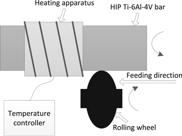
Figure 1. The schematic diagram of SRLT treatment.
Download figure:
Standard image High-resolution image2.2. Fretting friction and wear test
The fretting friction and wear properties were tested by SRV tribometer at room temperature without lubrication. The counter rubbing ball materials were GCr-15 bearing steel and Si3N4ceramics, and the diameter was 10 mm. The load of 10 N was loaded on the sample by the counter friction ball and the specimen remained stationary in the process of test. The samples were cut from HIP Ti-6Al-4V bar treated by SRLT. The test diagram and parameters are shown in figure 2 and table 3 respectively. Coefficient of friction (CoF) would be obtained by the data acquisition system during each test. The fretting test was repeated three times in the same conditions to reduce the degree of data dispersion. All the samples were ultrasonically washed in acetone for 10 min before test.
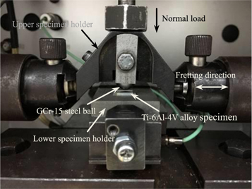
Figure 2. The picture of fretting tribometer friction and wear test.
Download figure:
Standard image High-resolution imageTable 3. The parameters of fretting test.
| Frequency (Hz) | Load (N) | Stroke (μm) | Time (min) |
|---|---|---|---|
| 10 | 10, | 200 | 30 |
2.3. Surface layer characterization
The cross-section of each sample was gradually ground by SiC abrasive papers from the 180 to 3000 grit, and then polished by diamond polishing agent. Finally the cross-section was etched in Kroll solution. The change of microstructure was observed using FEI Quanta 200 SEM. The further TEM analysis was conducted by FEITECNAI G2 S-TWIN F20 and the sample was prepared by FIB using Ga ion. The chemical composition was analyzed by EDS integrated into SEM equipment. The residual stress was measured by Rigaku Automate II equipment using the sin2 ψ method and the constituent phases were analyzed in the 2θ range of 30°−80°. Surface roughness and wear track profile were measured by SMS EXPERT 3D surface profiler. The microhardness was measured by MVS 1000 D1 Vickers microhardness tester (load 0.25N and dwell time15 s). Each reported value was the average of three measurements taken at different locations.
3. Results and discussion
3.1. Microstructure and composition
The microstructure of HIP Ti-6Al-4V alloy after SRLT treatment is shown in figure 3. An obvious plastic deformation is exhibited in material surface layer. The plastic deformation direction of material showing is consistent with the feed direction due to the combination of squeeze and friction effect of rolling wheel. It is significant that surface rolled sample at160 °C (figure 3(d)) has the thicker plastic deformation layer than the sample treated by surface rolling at room temperature (figure 3(a)). No obvious dividing boundary can be found between material deformation layer and the internal matrix. Moreover the composition phases in figure 3(d) are refined and uniformly arrange in parallel. This is the obvious difference compared to the coarse composition phases with the messy distribution in inner material substrate. Now the size of β phase has become very small and is squeezed into α phase in the plastic deformation region of figure 3(d). The low-heating temperature will decline material yield strength, produce material softening effect and reduce the friction between rolling wheel and HIP Ti-6Al-4V bar, and then the severe plastic deformation of the material will be produced by surface rolling. However the composition phases of the plastic deformation region obtained by the sample treated by surface rolling at room temperature in figure 3(a) are also elongated and become curved. It can be seen in figure 3(a) that α phase accounts for a relatively large proportion in HIP Ti-6Al-4V alloy. It is hcp structure and has the less slip systems, and not easy to produce the plastic deformation. Therefore the process of surface rolling treatment at room temperature has a small impact on material plastic deformation and grain refinement effect. The thickness of plastic deformation layer is very thin. However the low-heating behavior during surface rolling treatment can effectively improve material plastic deformation mechanism. Finally surface modification layer in figure3(d) has the larger plastic deformation and is composed of the denser α + β phase. Meanwhile the strain hardening and compressive residual stress will be introduced in material surface layer by the large contact load and material repeated plastic deformation [15].
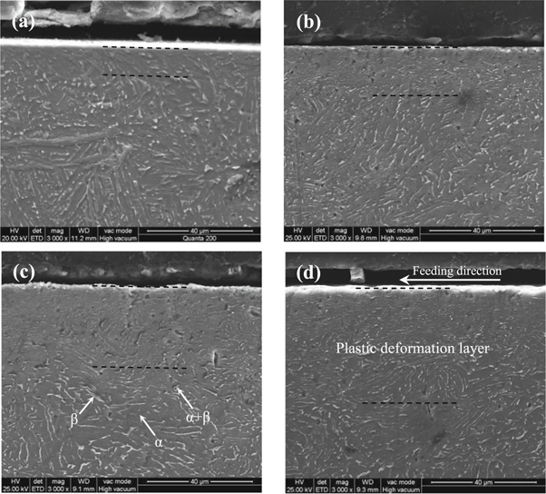
Figure 3. The cross-section pictures of HIP Ti-6Al-4V alloy after SRLT treatment: (a) surface rolled sample at 25 °C; (b) Surface rolled sample at 80 °C; (c) Surface rolled sample at 120 °C; (d) Surface rolled sample at 160 °C.
Download figure:
Standard image High-resolution imageTEM analysis for material microstructure of surface modification layer (figure 3(d)) of surface rolled sample at 160 °C is shown in figure 4. The chose depth range is 2 to 6 μm below material surface. As shown in figure 4(a) that the smallest grain size is about tens of nanometers (red region). This illustrates that SRLT treatment can effectively refine the grains in material plastic deformation region. The gray bands (marked by white arrows) in figure 4(a) will be generated by the high-density dislocations approximately parallel to each other and possibly with the same Burgers vector. The denser dislocations occurred in figure 4(b) can be explained by material uneven microstructure. When the dislocations slip in some planes and encounter some obstacles. Then the dislocations will curl and stack and the dislocation density increase accordingly [16]. Generally a large number of dislocation slips can effectively improve the microscopic defects (void or gap) of surface modification layer and achieve material plastic deformation. This will help to improve the microhardness in materials surface modification layer. However the annihilating, accumulating and rearranging of dislocation movement result in the grain boundaries are not very clear in figure 4(b). Moreover the low-heating temperature will increase the grain boundary migration rate and grain deformation energy. Therefore surface modification layer produced by surface rolled sample at 160° has a comparatively large plastic deformation. But some dislocation bands also exist interior the grains. The grain space is rearranged by the behavior of dislocations gliding, accumulation and tangle with the continue increasing of local elastic and plastic strain,. Then the original grain will be subdivided into the subgrains (as marked by the white arrows in figure 4(b)). The selected area '2' electron diffraction in figure 4(b) has the continuous ring patterns. This indirectly proves the existence of subgrains. Some straight and parallel dislocation bands can be found in figure 4(c) when the area '1' of figure 4(a) is further enlarged. The corresponding high-resolution image (figure 4(d)) shows that the direction of the stripes in region '3' is almost perpendicular to that in region '4'. This can be explained by the different stripes encountering by a certain angle, and some parallel stripes will be formed with a new angle after experiencing a large plastic deformation. The triangular junction of grain boundaries in figure 4(e) will be the main nucleation location due to the higher lattice latent energy. It can be found that the dislocation density in figure 4(f) is obviously decreased compared to that in figure 4(b). The corresponding selected area '5' electron diffraction in figure 4(f) has the discontinuous ring patterns which indicate the presence of grain and subgrain. Moreover the small band structure and low dislocation density can be seen interior the grain or subgrain. This illustrates that the effect of grain refinement and plastic deformation caused by SRLT treatment is progressively decreased with the increasing of material depth.
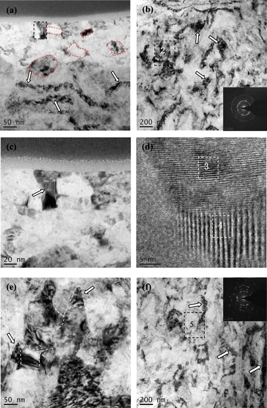
Figure 4. Bright field pictures at the depth range of 2–6 μm from the sample (treated by surface rolling at 160 °C) surface: (a) 2 μm depth; (b) 4 μm depth; (c) The enlarged view of area'1'; (d) The high resolution image of Fig. (c); (e) The enlarged view of area'2'; (f) 6 μm depth.
Download figure:
Standard image High-resolution imageThe XRD patterns analysis for SRLT-treated samples is shown in figure 5(a). It can be found that surface rolled sample at 160 °C has the broader diffraction peak than the sample treated by surface rolling at 25 °C. In general, the diffraction peak broadening can be caused by the effect of micro strain and grain refinement [14]. It also illustrates that SRLT treatment has the better effect of grain refinement and strain strengthening than surface rolling treatment at room temperature. However the oxide phase is not found in the diffraction patterns because of the lower material heating temperature. But the EDS analysis result in figure 5(b) still proves some oxygen elements existed in material surface. They mainly come from material itself and the air.
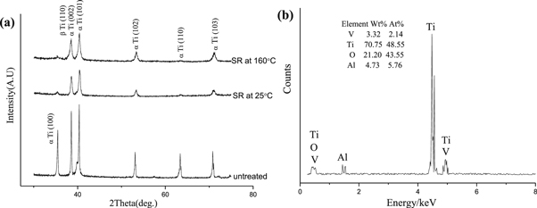
Figure 5. The composition analysis of surface rolled sample at 160 °C: (a) XRD patterns; (b). EDS.
Download figure:
Standard image High-resolution image3.2. Microhardness and surface roughness
As shown in figure 6(a), the microhardness values are measured in material surface-modified layer along the depth direction to estimate the hardening depth of SRLT-treated samples. It is obvious that the samples treated by SRLT have the higher surface microhardness values than the untreated sample, and progressively increase with material heated temperature. But the maximum surface microhardness values obtained by SRLT-treated sample are still lower than that of surface rolled sample at room temperature. This proves that the cold work hardening has an important effect during surface strengthening. However the depth of material hardening layer of SRLT-treated sample is significantly different to surface rolled sample at room temperature. The maximum hardening depth (about 90 μm) obtained by surface rolled sample at 160 °C is several times that obtained by surface rolled sample at normal temperature. A thick surface hardening layer can improve material deformation resistance during microhardness measurement and enhance the tensile strength and fatigue performance of the material. It is well known that the high material surface microhardness and thick hardening layer can improve the situation of material surface mechanical damage in actual application [17]. Although surface strengthening effect of the rolling wheel is very limited, the increased microhardness in the plastic deformation region can be explained by the refined grains, high density dislocations, strain hardening and reduced micro-defects [18]. Of course, the compressive residual stress produced by SRLT treatment in material surface layer also helps to increase material deformation resistance.
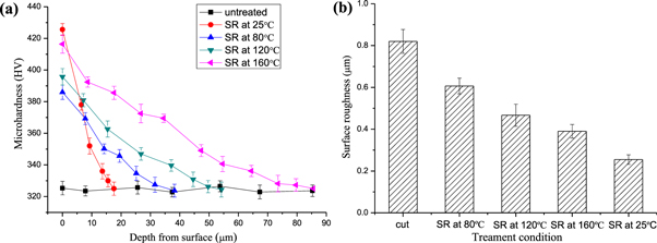
Figure 6. Surface roughness and hardening depth of SRLT-treated samples: (a) depth profile of Vickers microhardness; (b) surface roughness.
Download figure:
Standard image High-resolution imageThe different processing method will show the different material surface morphology. The variation trend of surface roughness of SRLT-treated samples is shown in figure 6 (b). Material roughened surface produced by cutting become smoothly through SRLT treatment, and the roughness values are progressively reduced as material heating temperature increases. However surface rolled sample at 25 °C shows the smallest surface roughness value due to the smoothing effect of cold working. Surface roughness values are reduced by 60% relative to the untreated sample. The gradually decreasing surface roughness of SRLT-treated samples is mainly because of material increased plastic deformation caused by the progressively increased material heating temperature. But SRLT treatment is conducted under dry friction conditions. The rolling wheel has a scrolling and sliding friction in the direction of circumference and feeding respectively. Moreover the high working load will increase the friction interaction between rolling wheel and material. Material yield strength is declined by the low-heating temperature. Therefore a slight adhesion behavior will emerge on material surface of SRLT-treated samples. This also explains why the lowest surface roughness values of SRLT-treated sample are still higher than that of surface rolled sample at room temperature.
3.3. Residual stress
As an important indicator of material surface properties, the compressive residual stress is introduced in material surface by SRLT treatment (figure 7). The residual stress is usually related to the yield strength and plastic deformation. When material heating temperature is progressively increased, the compressive residual stress in material surface produced by surface rolling treatment will be released due to the surplus energy and shows a decline trend. In addition, the low-heating temperature also decreases material yield strength. The measured results indicate that surface rolled sample at 160 °C has the smallest stress values. However surface rolled sample at room temperature needs the higher contact pressure to overcome material original yield strength and produce the plastic deformation. So it shows the higher compressive residual stress values compared to SRLT-treated samples in the same loading conditions. Generally the high residual stress values produced in material surface will be beneficial to improve the resistance of material fretting wear [19]. But the compressive residual stress also existed in the cutting material surface. This can be explained by material plastic deformation produced by cutting process [20, 21]. The plastic deformation of material surface modification layer needs to be achieved by relying on the large number of dislocations. Therefore it can be inferred that the compressive residual stress extends to the depth corresponding to the dislocation generation region [11].
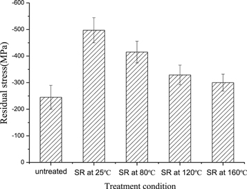
Figure 7. Surface compressive residual stress of SRLT-treated samples.
Download figure:
Standard image High-resolution image3.4. Fretting friction and wear behavior
The Coefficients of friction (CoF) of SRLT-treated samples are shown in figure 8. It is obvious that the fluctuation range (figure 8(a)) and steady-state value (figure 8(b)) of CoF curves are progressively reduced with the increasing of material heating temperature. The sample treated by surface rolling at 160 °C shows the lower initial stage and the smaller steady-state value than the cut sample. But this value is still slightly higher than the steady-state value of CoF produced by surface rolled sample at 25 °C. The main reasons can be ascribed to the comparatively low surface mechanical properties of SRLT-treated samples which includes the compressive residual stress and microhardness. Moreover the high surface roughness also can decrease the friction properties and result in the increasing of CoF. However the thick hardening layer produced by surface rolled sample at 160 °C can improve material deformation resistance and show the good friction properties. When the heating temperature of material is 80 °C and 120 °C respectively, the samples treated by SRLT show the relatively poor friction performance compared to the cut sample. Now the CoF curves have a larger fluctuation and higher steady-state position.
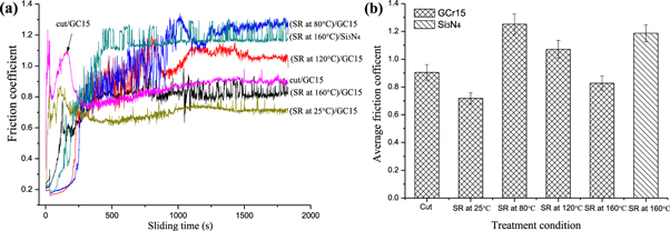
Figure 8. The CoFs of SRLT-treated samples: (a) the change trend of CoF; (b) the average steady-state of CoF.
Download figure:
Standard image High-resolution imageThis also indirectly proves that the cold work hardening has a very important impact on material friction resistance. In addition, the interaction of material transferring layer and worn particles between the sliding interfaces will also result in the large fluctuation range of CoF [22]. As shown in figure 9(f), some Ti-6Al-4V material bonded to the surface of counter grinding ball. It illustrates that the sample treated by SRLT is easy to wear and form some big bonding blocks. The EDS analysis (figure 9(h)) of the bonding block indicates that it is mainly constituted by Ti and O element. Of course, the high steady-state position of CoF curve also illustrates that the sample has occurred severe wear. Although the process of SRLT treatment can increase material deformation mechanisms, it also will decline material fretting friction and wear properties. When Si3N4 (the higher hardness and better wear resistance) is selected as the counter rubbing material, CoF curve produced by surface rolled sample at 160 °C is raised and has the small fluctuation. Therefore the counter rubbing material also plays an important role in the friction properties of SRLT-treated samples.
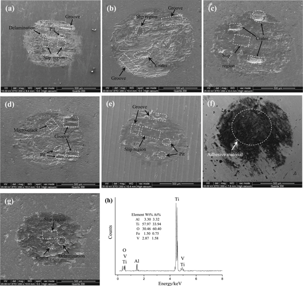
Figure 9. SEM pictures of wear scars for SRLT-treated samples:(a) (surface rolled sample at 25 °C)/GCr15; (b) (surface rolled sample at 80 °C)/GCr15; (c) (surface rolled sample at 120 °C)/GCr15; (d) (surface rolled sampleat160 °C)/GCr15; (e) the cut sample/GCr15; (f)GCr15 wear surface; (g) (surface rolled sample at 160 °C)/Si3N4; (h) EDS analysis for the adhesive material in Fig. (f).
Download figure:
Standard image High-resolution imageFigure 9 shows the fretting wear tracks corresponding to the CoFs of SRLT-treated samples. It is obvious that the area of wear scar shows a gradually reduce trend from figures 9(b) to 9(d). So the wear resistance of SRLT-treated samples is progressively improved. However the area of wear scar (figure 9(d)) obtained by surface rolled sample at 160 °C is obviously larger than surface rolled sample at 25 °C (figure 9(a)), and close to untreated sample (figure 9(e)). The low surface mechanical properties, high surface roughness and increased deformation mechanisms can be the main reasons for the declined wear resistance of SRLT-treated samples. The large wear areas of figures 9(b) and (c) indicating the samples happen severely wear during the fretting test. This also explains why the corresponding steady-state position of CoF curve is so high. Some obvious grooves, slip regions and craters can be found in the worn surfaces. They are mainly produced by the abrasive wear, delamination and adhesion wear. Meanwhile the effect of delamination and abrasive wear on the worn surfaces is gradually weakened with the increasing of material heating temperature. Surface rolled sample at160 °C shows the similar wear areas in figures 9(d) and (g). They are obtained by rubbing with Si3N4 and GCr 15 respectively. But the wear scars are significantly different. The worn surface in figure 9(d) shows some small grooves and pits. Now the sliding wear plays the main role during the wear test. But the wear degree is more serious than surface rolled sample at 25 °C (figure 9(a)). Some micro cracks even appear in the wear region caused by material delamination. However the wear surface in figure 9(g) is mainly composed of several craters and some sliding region with the smooth surface. Several block materials existed in the worn surface and easily worn away. So the main wear mode is delamination and abrasive wear. The worn surface (figure 9(e)) of untreated sample is like that (figure 9(d)) of surface rolled sample at 160 °C. This indicates the relatively poor wear resistance of SRLT-treated samples.
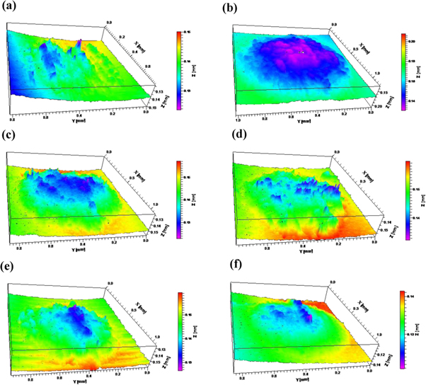
The material loss of SRLT-treated specimens shows a gradually decrease trend in figure 10. Surface rolled sample at 160 °C (figure 10(d)) has the less material loss than the cut sample (figure 10(e)), but it is obviously larger than surface rolled sample at 25 °C(figure 10(a)). This also proves that the sample treated by SRLT has the comparatively severe wear. Moreover material loss of the samples is also significantly increased when the counter grinding material changes to Si3N4 (figure 10(f)) from GCr15 (figure 10(d)). It indicates that the counter grinding material with good wear resistance will also intensify the wear of SRLT-treated sample. Although SRLT-treated samples have the poorer fretting friction properties compared with surface rolled sample at room temperature, the material in surface modification layer shows the better microstructure and plastic deformation. Therefore this method can be combined with other surface modification processes, and finally to realize the purpose of improving material fretting wear properties.
Figure 10. Surface 3D morphologies of wear scars corresponding to SRLT-treated samples: (a) (surface rolled sample at 25 °C)/GCr15; (b) (surface rolled sample at 80 °C)/GCr15; (c) (surface rolled sample at 120 °C)/GCr15; (d) (surface rolled sample at 160 °C)/GCr15; (e) the cut sample/GCr15; (f) (surface rolled sample at 160 °C)/Si3N4.
Download figure:
Standard image High-resolution image
4. Conclusions
- (1)The composition phase and plastic deformation layer of surface rolled sample at 160 °C are obviously improved relative to the initial state and surface rolled sample at room temperature and shows the finer grains.
- (2)The mechanical properties of surface modification layer of SRLT-treated samples are significantly increased compared to the cut sample. But they are still lower than that of surface rolled sample at room temperature. The main reason is due to the decrease in yield strength and stress release of the material caused by the low-heating temperature during SRLT treatment and the lack of cold work hardening.
- (3)Through the comparative analysis of fretting friction and wear properties, it can be judged that surface rolled sample at 160 °C shows the better wear resistance than the cut sample. But it still has the poorer friction and wear properties than surface rolled sample at 25 °C. The specific reasons are as follows: the relatively low surface microhardness and residual stress, the high surface roughness, and the increased deformation mechanism.
Acknowledgments
We are very grateful to the national metal material near net forming engineering technology research center of south china university of technology for providing equipment. This study was funded by the National Natural Science Foundation of China (51704073) and the startup fund of doctoral research (11827).
Conflict of Interest
The authors declare that there is no conflict of interests regarding the publication of this article.