
Abstract
The surface of orthopaedic bone implants is in most cases formed by porous plasma spray. The introduction of 3D printing into the production of implants has made it possible to replace plasma spray with a trabecular bone-like structure that can be fabricated by 3D printing. The principle is to create a suitable surface porosity for anchoring the implant in the bone and adapting the modulus of elasticity to the bone properties. The elastic behaviour of both the structures can be compared by means of a compression test, but it is not possible to compare the modulus of elasticity at the local sites. The aim of the work was to verify the possibility to use the nanoindentation method for the local testing of the modulus of elasticity. The selected method made it possible to map the so-called reduced modulus of elasticity at the precisely defined places. Specifically, the 3D printed trabecular structure of Ti6Al4V ELI was compared with titanium plasma spraying. The printed structure with a bulk porosity of 77% showed the local modulus of elasticity in the range of 57–97 GPa depending on the test site. In contrast, for the plasma spray with a volume porosity of 28%, the modulus of elasticity was around the average value of 54 GPa. At the same time, the microstructure and chemical composition were analysed at the critical points of the structure crossover or the transition from the bulk material to the trabecular structure. No change in the microstructure or chemical composition was observed. Both structures bring the modulus of elasticity closer to the bone modulus of elasticity, but 3D printing offers more possibilities to modify the elastic behaviour and the shape and pore size as well.
Export citation and abstract BibTeX RIS

Original content from this work may be used under the terms of the Creative Commons Attribution 4.0 licence. Any further distribution of this work must maintain attribution to the author(s) and the title of the work, journal citation and DOI.
1. Introduction
Additive manufacturing (AM) using laser sintering of metal powder allows the production of orthopaedic bone implants with a unique surface porous structure similar to a trabecular bone. The structure is formed from the regular strut-based lattice optimised for ideal bone cell proliferation [1]. In one technological step, the method based on 3D printing allows one to print the volume part of implant and, at the same time, create a porous trabecular structure on its surface. This is a clear advantage over the standard manufactured implants where the proven solution to ensure the perfect fixation of the implant is to apply hydroxyapatite, titanium plasma spray or a combination thereof to its surface [2].
The porous spray coating increases the surface roughness and creates a larger contact area for the bone cell growth. On the other hand, there is a risk that the spray adhesion to the implant surface can fail [3]. Another limitation of the plasma spray is its structure created from closed pores without the possibility of significant optimisation using process parameters.
In contrast, 3D printing can better mimic the trabecular bone structure on the implant surface by creating open pores of the desired shape and size [4]. The implant surface then consists of a structure similar to a '3D mesh', where the basic building elements have dimensions in hundreds of μm and their cross-section in tens of μm correspond to a few sintered powder grains. The perfect bonding of these grains then determines the resulting mechanical properties, such as the strength or the modulus of elasticity.
Although a large number of papers have been published in the literature to experimentally evaluate the properties of 3D printed trabecular structures [5–14], or to theoretically determine the properties using finite element computer modelling [15], publications dedicated to the comparison with plasma sprays only occur sporadically. For example, comparing titanium plasma sprays to a trabecular 3D printed structure of Ti6Al4V ELI based on the in vitro osteoblastic response [16] and in vivo evaluation of cancellous bone-implant interfaces [17] was published.
The properties of both tested structures can be compared from the perspective of two basic criteria. The first criterion is the modulus of elasticity estimated in the local places where it can differ significantly. The second criterion is the porosity, which influences the ingrowth of the bone cell into the structure and prevents movement at the bone-implant interface.
The aim of this work was to find a suitable experimental method for the local testing and comparison of the elastic behaviour of the porous structures, 3D printed trabecular structure from Ti6Al4V ELI and titanium plasma spray. The nanoindentation [18] method was chosen, which makes it possible to map the so-called reduced modulus of elasticity in the precisely determined places. At the same time, the microstructure and chemical composition were analysed at critical points, such as the struts crossover or the transition from the bulk material to the trabecular structure. The porosity and microstructure were also included among the other evaluated parameters.
2. Material and methods
2.1. Materials
The rhombic dodecahedron trabecular structure (figure 1) was chosen on the recommendation of the implant manufacturer ProSpon, which uses it for surface treatment of 3D printed implants as a replacement for plasma spray. To test the mechanical properties of the structure, test specimens were produced by ProSpon using 3D printing of the metallic powder Ti6Al4V ELI (ISO 5831-3, Concept Laser CL 41TI ELI) with a grain size of 10–45 μm. Direct metal laser sintering (DMLS) technology was used on a Concept Laser M2 cusing printer. The samples were manufactured using the same process parameters, which ProSpon uses for printing medical implants.

Figure 1. A rhombic dodecahedron trabecular structure.
Download figure:
Standard image High-resolution imageThe overall dimensions of the samples were 10 × 5 × 5 mm. One half of the sample was printed as a bulk material and the other half in the form of a trabecular structure (figure 2). The samples were then vacuum annealed at 840 °C to remove the residual stress. The manufacturing process and subsequent heat treatment of the specimens corresponded to the production of commercial implants in order to simulate the behaviour of a real implant.

Figure 2. The 3D printed Ti6Al4V ELI sample with the bulk part and the trabecular part.
Download figure:
Standard image High-resolution imageTitanium plasma spray samples were used for the comparison with the 3D printed structure. They were prepared by the atmospheric plasma spraying (APS) method under standard conditions, which are used for coating commercially manufactured implants from ProSpon. The test specimens were produced by company Fluxamat using the metallic powder Ti 99.5% (ISO 5831-2) with a grain size of 180–250 μm. The 828 ± 14 μm titanium spray was applied to the surface of the Ti6Al4V ELI alloy. Three samples from each group were prepared for testing.
2.2. Nanoindentation
Various shapes of indenters, such as Vicker, Berkovich, sphere or conical, can be used to measure the nano-hardness and reduced modulus of elasticity. For determining the local properties, the volume affected by the indenter should be minimal. From this point of view, the Berkovich indenter is the most suitable for the mapping method [19, 20].
A NanoTest (Micro Materials Ltd) nano-hardness tester with a Berkovich type indenter was used. The constant load rate of 0.625 mN s−1 for the loading and unloading with a 10 s dwell at a maximum load of 400 mN was applied for each sample. The selected high load allowed one to elastically deform the bulk material and to simultaneously elastically deform the strut. The distance between the indentations was set as 50 μm. During each test, the indentation depth was corrected for both the thermal drift and elastic compliance of the test frame. The tests were conducted at a constant temperature of 20 °C. The tip shape calibration was performed using fused quartz as a reference material. The indentation depth h was used for the calculation of the diamond area of A = 24.5h2 with an indenter geometry shape factor of β = 1.034.
For the trabecular structure, the indentations were performed at the strut crossings and in the region between these points where we predicted the highest differences in the modulus of elasticity. The titanium plasma spray was measured in random places. The measurement places of both structures were metallographically ground and polished.
2.3. Compression test
The static compression tests were carried out using an Instron 5582 instrument at room temperature following the ISO 13314:2011 standard. The standard specifies a test method for compressive properties of porous and cellular metals with a porosity of 50% or more. A load was applied to the trabecular structure sample at a constant deformation rate of 0.1 mm min−1. The elastic gradient (Eσ20–70) was calculated as the gradient of the elastic straight line between two stress values, namely σ20 and σ70 (σ20 and σ70 correspond to 20% and 70% of the plateau stress, σpl). The plateau stress is defined as the arithmetical mean of the stresses between 20% and 40% of the compressive strain.
2.4. Porosity
The surface and volume porosities were compared in the samples with the trabecular structure and titanium plasma spray. The surface porosity was examined using a Nikon SMZ1500 stereo microscope. Nikon NIS-Elements were used for the evaluation. Using the thresholding function, a so-called binary layer was created (the areas containing pores are separated from the background).
A gravimetric method was used to determine the volume porosity. The mass m of a sample of known volume V obtained from the sample dimensions was determined on a laboratory scale with an accuracy of 10–4 g. The density of the porous sample ρ was calculated from the ratio of the mass m to the volume V and the porosity P from equation (1), where ρ0 is the reference density of the non-porous materials. The plasma spray density was tested on the spray coatings separated from the base material.

2.5. Chemical composition and microstructure
The chemical composition and surface topography were analysed using a JEOL JSM 7600F scanning electron microscope with an energy-dispersive x-ray spectroscopy (EDS) analyser. The microstructure of the 3D printed samples was determined on the cross-section of the metallographic polished sample using a Nikon Neophot metallographic microscope. The microstructure was etched by Kroll's reagent.
3. Results and discussion
The mechanical properties of the 3D printed trabecular structure depend on the choice of the appropriate geometry. The arrangement, length and thickness of the struts from which this structure is made must be designed so as to maintain the required strength while maintaining a sufficient porosity of the structure. For the trabecular structure tested, a strut diameter of 400 μm and a length of 1500 μm were chosen. The actual dimensions were measured using a light microscope (figure 3) and corresponded to the required dimensions with a maximum deviation of around 1%.

Figure 3. The strut dimensions of the 3D trabecular structure from Ti6Al4V ELI.
Download figure:
Standard image High-resolution imageThe elastic behaviour of this structure was tested locally along the length of the struts, including their crossing points. At the same time, the chemical composition and microstructure were evaluated in these places. The modulus of elasticity of the plasma spray was also tested locally.
A theoretical calculation was also performed involving the elastic behaviour of the structure as a whole. To calculate it, it was first necessary to experimentally determine the porosity of the structure.
3.1. Porosity
The densities of the tested samples were determined by the gravimetric method. If we consider the reference density of the non-porous material as 4.430 g.cm−3 for the Ti6Al4V ELI and to simplify the titanium density of 4.506 g.cm−3 for the plasma spray, then the calculated values will correspond to the volume porosity given in table 1. The residual porosity of the Ti6Al4V ELI bulk material was 3.20%. Similar values in the range of 1.4%–5.7% are also reported in the publications [21, 22]. Using the high isostatic pressing (HIP) method, the residual porosity can be reduced up to 0.1% [21].
Table 1. The volume porosity and density.
| Density [g.cm−1] | Volume porosity [%] | |
|---|---|---|
| 3D printed Ti6Al4V ELI - bulk | 4.29 | 3.20 |
| 3D printed Ti6Al4V ELI - trabecular | 1.01 | 77.26 |
| Ti plasma spray | 3.23 | 28.23 |
For the bone cell ingrowth, it is important whether the porosity is open or closed. Using the 3D printing, it is possible to create a structure with pores going through the entire structure (figure 4(a)). In contrast, the plasma spray principle only allows closed pores to be formed (figure 4(b)).

Figure 4. The cross-sections of: (a) the trabecular structure of Ti6Al4V ELI and (b) the porous Ti plasma spray.
Download figure:
Standard image High-resolution imageThe osseointegration of the implant is also fundamentally influenced by the roughness and the porosity of the surface. Therefore, the surface porosity of the 3D printed structure (figure 5(a)) and the plasma spray (figure 5(c)) were first evaluated. A binary layer separating the pores (red surface) from the bulk material was created by thresholding. The highlighted pore area is shown in figure 5(b) and in figure 5(d) for the 3D printed structure and for the plasma spray, respectively.

Figure 5. The surface porosity of: (a) the Ti6Al4V ELI trabecular structure, (b) with a red binary layer and (c) the porous Ti plasma spray, (d) with a red binary layer.
Download figure:
Standard image High-resolution imageThe measurement was performed repeatedly on an area of 5 × 4 mm. The total porosity area is given as a percentage in table 2. The surface porosity of the trabecular structure corresponds to the real implant surface. In other cross-sectional planes, the surface porosity will be different. Compared to the plasma spray, up to three times more porosity can be achieved by the 3D printing. In addition to the porosity, the pore diameter is an important parameter that affects the ability of the bone cells to grow through the porous structure. Table 2 shows the measured minimum, maximum and average pore areas. The square roots of these areas give us approximate information about the pore diameter for the trabecular structure and for the plasma spray in the range 728–878 μm and 141–529 μm, respectively.
Table 2. The surface porosity.
| Area [mm2] | Porosity [%] | |||
|---|---|---|---|---|
| Minimum | maximum | Average | ||
| 3D rinted Ti6Al4V ELI - trabecular | 0.53 | 0.77 | 0.70 | 46.00 |
| Ti plasma spray | 0.02 | 0.28 | 0.06 | 16.30 |
The ideal pore diameter for the bone ingrowth is reported to be between 100 μm and 500 μm [23]. On the other hand, for pore sizes ranging from 500 μm to 900 μm, it has been reported that smaller pores promote cell adhesion and greater cell proliferation. The ideal pore size is then around 600 μm [24]. Using 3D printing, the geometry of the trabecular structure under test could be adapted to these dimensions or combined with different pore sizes while maintaining the desired mechanical properties.
3.2. Elastic properties
3.2.1. Local modulus of elasticity
The local testing of the elastic behaviour was performed using the nanoindentation method, from which the total depth of the indenter penetration can be determined very precisely. From the relief of the unloading curve, it is then possible to determine the depth due to the elastic and plastic deformation, so-called elastic and plastic depth, as well as the slope directive to determine the so-called reduced modulus of elasticity by the Olivier-Pharr method [25, 26].
The nanoindentation was performed on the metallographically ground and polished surfaces of the trabecular structure. Since the structure is not geometrically symmetrical, two directions of testing were chosen: perpendicular to the surface (figure 6(a)) and parallel to the surface (figure 6(b)). The indentation was performed at: (a) the strut crossings, (b) near the strut crossings, (c) midway between the two crossings, and (d) in the bulk part of the sample. In the parallel direction, it was not possible to metallographically ground the material, which would clearly correspond to positions (a) and (c), therefore the measurement in this direction was taken for reference only.
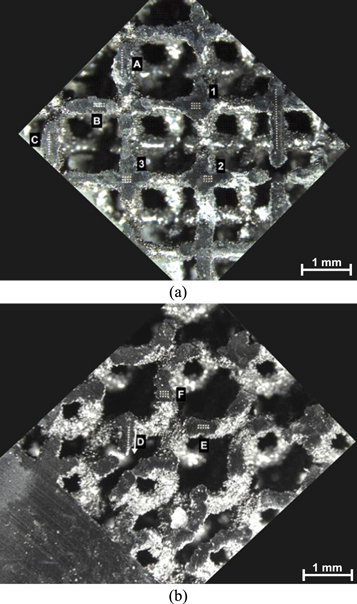
Figure 6. The testing places of the nanoindentation tests of the Ti6Al4V ELI trabecular structure: (a) the top of the sample (the perpendicular direction) and (b) the side of the sample (the parallel direction).
Download figure:
Standard image High-resolution imageThe results of testing in the perpendicular direction of the trabecular structure are presented in figure 7. The measured values for the reduced modulus of elasticity (figure 7(a)) as well as the values of the nano-hardness (figure 7(b)) are presented. At the same time, there is also a comparison with the values obtained for the titanium plasma spray.

Figure 7. The nanoindentation tests of Ti6Al4V ELI and the Ti plasma spray: (a) the reduced modulus of elasticity and (b) the nano-hardness.
Download figure:
Standard image High-resolution imageThe reduced modulus of elasticity in figure 7(a) is affected by the strut deflection. This includes the modulus of elasticity of the material itself, plus the contribution given by the strut deflection. The measured values of the modulus of elasticity ranged from 57.04–97.07 GPa and 143.38 GPa for the bulk part. A similar course was also found in the nano-hardness (figure 7(b)), ranging between 3.96–4.30 GPa and 4.88 GPa for the bulk part.
For the titanium plasma spray, the elasticity modulus of 53.80 GPa was comparable to the modulus of 57.04 GPa in the middle of the strut. On the other hand, the nano-hardness here was 4.35 GPa compared to the lower nano-hardness of 3.96 GPa in the middle of the strut. The measured values for the plasma spray can be influenced by the formation of the titanium oxides (TiO), which are formed on the surface of the titanium powder during the atmospheric transport from the nozzle to the substrate surface [27]. For all the measurements of the porous structures, both the modulus of elasticity and nano-hardness were lower compared to the values for the bulk parts, where there is no elastic deformation given by the structure geometry. The maximal depths hmax, plastic depths hf and their ratios are given in table 3 as the averages from all the measurements. The lower ratio corresponds to fully elastic deformation and the higher ratio to the rigid–plastic behaviour.
Table 3. The maximal depths hmax at the maximal load, the plastic depths hf after unloading and their ratios.
| Maximal depth hmax [mm] | Plastic depth hf [mm] | hf/hmax | |
|---|---|---|---|
| Ti plasma spray | 2440 ± 50 | 1939 ± 41 | 0.79 |
| 3D printed Ti6Al4V ELI - between crossings | 2481 ± 61 | 2032 ± 59 | 0.82 |
| 3D printed Ti6Al4V ELI - near crossing | 2304 ± 59 | 1959 ± 44 | 0.85 |
| 3D printed Ti6Al4V ELI - crossing | 2227 ± 44 | 1952 ± 47 | 0.88 |
| 3D printed Ti6Al4V ELI - bulk | 2029 ± 55 | 1831 ± 56 | 0.90 |
The main aim of mapping the local modulus of elasticity of the porous structures was to describe the interaction of the structure surface with the bone tissue at individual sites. For a 3D printed structure, the local modulus of elasticity differed more than twice as much in the individual locations. On the contrary, the plasma spray changed the local modulus of elasticity only minimally. The local modulus of elasticity can also be used to model of the elastic behaviour of porous structures, where it can refine the elastic properties of the individual struts.
3.2.2. Flexural modulus of elasticity
The modulus of elasticity in bending area, the so-called flexural modulus of elasticity Ef, considering the strut as a very simplified case of a strut with two supports at the ends (figure 8), can be approximately calculated from the deflection in the middle of the struts.

Figure 8. A simply supported strut where X1 is the indentation between the crossings with the deflection that follows and X2 is the indentation at the crossing.
Download figure:
Standard image High-resolution imageThe similar principle to the three-point bending flexural test was used to verify the effect of strut deflection on the modulus Ef. Using the nano-indenter, it was possible to very precisely determine the total depth of the penetration of the indenter including the depth of the strut deflection (figure 9).
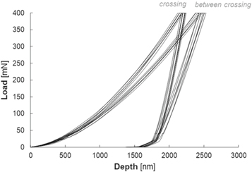
Figure 9. The difference in the load-depth data for the indentation at the strut crossing and for the indentation between the strut crossings with the elastic strut deflection that followed.
Download figure:
Standard image High-resolution imageThe modulus of elasticity Ef can then be derived from equation (2) of the three-point bending test for the circular beam:

where the maximum deflection δmax in the centre of the strut in figure 5 is obtained from the difference of the elastic depth of the indenter in the middle of the strut at X1 (the depth given by the elastic deformation of the material increased by the strut deflection) and at the crossing point of the strut at point X2 (it only includes the depth given by the elastic deformation of the material). The area moment of inertia for a solid cylindrical section can be calculated as:

where the diameter of strut d was 395 μm and the strut length L between the nodes was 1511 μm (see figure 3). The load applied in the middle of strut F was 400 mN. The resulting modulus Ef shown in table 4 reaches a value of 137.95 GPa. Generally, the flexural modulus of elasticity is equivalent to the modulus of elasticity. In our case, we can compare the value to the reduced modulus of elasticity of 143.38 GPa measured for the bulk portion (figure 7(a)). The resulting values are very similar, but may be subject to considerable error due to the simplification in the calculation and indentation itself (grinding the strut for the indentation, the rigid connection of supports to the strut, inaccuracies in the puncture placement, etc).
Table 4. The elasticity of a simple support strut with the load in the centre.
| d [mm] | L [mm] | F [N] | I [mm4] | Ø δmax [nm] | E [GPa] | |
|---|---|---|---|---|---|---|
| Strut of Ti6Al4V ELI | 0.395 | 1.511 | 0.400 | 0.001195 | 174.39 | 137.95 |
3.2.3. Effective modulus of elasticity
In addition to local elastic properties, it is important to know the behaviour of the structure as a whole. The elastic properties of the porous structure can be described by the so-called effective modulus of elasticity, which is not identical to the modulus of elasticity of the bulk material. It consists of a component comprising the elastic behaviour of the bulk material and a component comprising the elastic behaviour given by the geometry of the porous structure. It can be determined either experimentally by a compression test [9, 28] or theoretically on the basis of the empirical relationship (4) if we know the porosity of the material [12, 29, 30]:

where E and ρ are the effective modulus of elasticity and density of the porous material, E0 and ρ0 are the modulus of elasticity and density of the bulk material. C1 includes all of the geometric constants of proportionality and n1 is the density factor. For simplicity, we can consider C1 ≈ 1 and n1 ≈ 2 for the given shape and material. Table 5 shows the calculated elastic modulus values of the 3D printed [31, 32] and plasma sprayed material.
Table 5. The effective modulus of elasticity.
| ρ0 [g.cm−1] | ρ [g.cm−1] | E0 [GPa] | E [GPa] | |
|---|---|---|---|---|
| 3D printed Ti6Al4V ELI | 4.43 | 1.01 | 120.00 | 6.24 |
| Ti plasma spray | 4.51 | 3.23 | 105.00 | 53.95 |
The experimental determination of the modulus of elasticity using the compressive test is illustrated in figure 10. The graph shows the dependence of σ (compressive stress) on ε (compressive strain). The gradient of the elastic straight line between the two values of σ20 and σ70 correspond to a modulus of 2.82 GPa. Similar values in the range of 1.50–3.50 GPa are given in the publications dealing with testing structures from Ti6Al4V ELI with the corresponding shapes, dimensions and porosity [21, 33–35]. In comparison with the theoretically determined modulus of 6.24 GPa (table 3), it is more than two times less. The theoretical calculation is strongly dependent on the determination of the Gibson–Ashby parameters C1 and n1 in equation (4) [11, 33], this may be one of the reasons for the different values.
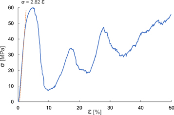
Figure 10. The stress-strain curve from compression testing of the Ti6Al4V ELI trabecular structure.
Download figure:
Standard image High-resolution image3.3. Chemical composition
The mechanical behaviour of the structure is influenced by the crossing points of the elements, which represent an increased risk in the case of the imperfect bonding of the powder grains during the laser sintering. The reason for this is the heat dissipation rate differs at the point of printing the compact material and at the point of the fine 3D structure. The result may be a change in the microstructure or the possibility of oxides forming at the joint site due to the residual atmosphere. The chemical composition as well as the microstructure were analysed at these critical points of the 3D printed trabecular structure.
The analysis obtained by the EDS method in figure 11 shows that the chemical composition of the line passing through the interface connecting the trabecular structure to the volumetric portion does not change and corresponds to the values shown in table 6 (shown without the O and Fe contents, varying between the resolutions). The values correspond to the chemical composition of the Ti6Al4V ELI input powder.

Figure 11. The chemical composition of the structure-volume connection of the 3D printed Ti6Al4V ELI (chemically not etched).
Download figure:
Standard image High-resolution imageTable 6. The chemical composition of the 3D printed Ti6Al4V ELI.
| Ti6Al4V ELI | wt% | at% |
|---|---|---|
| Ti | 90.31 | 86.50 |
| Al | 5.97 | 10.15 |
| V | 3.73 | 3.36 |
The chemical composition of the titanium plasma spray consists of titanium and titanium oxides that form on the powder surface during the transport of the atmosphere from the nozzle to the sample surface [27]. This was confirmed by the results of the chemical composition analysis of the test titanium plasma spray shown in table 7.
Table 7. The chemical composition of the Ti plasma spray.
| Ti plasma spray | wt% | at% |
|---|---|---|
| Ti | 78.50 | 54.95 |
| O | 21.50 | 45.05 |
3.4. Microstructure
The microstructure of the 3D printed Ti6Al4V ELI alloy after printing in figure 12(a) primarily consisted of the acicular martensite α' and β structure. Martensite α' has a hexagonal crystal lattice and mainly consists of slats or needles. The martensite in the structure is formed by the rapid cooling at the sintering site and causes higher material hardness [36, 37].

Figure 12. The microstructure of the 3D printed Ti6Al4V ELI (chemically etched by Kroll's reagent): (a) non-annealed and (b) annealed.
Download figure:
Standard image High-resolution imageAfter vacuum annealing, the microstructure of figure 12(b) was more homogeneous than that of the non-annealed material in figure 12(a) [38, 39].
The microstructure of the trabecular structure was evaluated in detail by SEM at the sites of the strut crossings, and, in particular, at the transition point from the bulk to the trabecular structure (figure 13). The lamellar microstructure does not change at this interface and forms a compact unit with the bulk portion.

Figure 13. The microstructure of the structure-volume connection of the 3D printed Ti6Al4V ELI (etched by Kroll reagent's).
Download figure:
Standard image High-resolution image
Based on the carried out tests, it was confirmed that nanoindentation can be very accurate method for testing the local elastic properties. The method is suitable for testing the porous materials with a defined geometric structure that do not show the rigid–plastic behaviour. However, there are few limitations affecting accuracy and repeatability of this method, such as an inaccurate grinding of the nanoindentation site, the inaccuracies in the indent placement or use of an unsuitable shape of the indenter (a sharp indenter increases lateral accuracy because the size of the affected volume is smaller than that of a spherical or flat one).
4. Conclusions
Based on the comparison of the 3D printed trabecular structure of the Ti6Al4V ELI with the titanium plasma spray, it was confirmed:
- The 3D printed trabecular structure showed a local modulus of elasticity in the range of 57.04–97.07 GPa depending on the site of testing. For the plasma spray, the local values did not change much and the modulus of elasticity reached an average value of 53.80 GPa.
- The porosity in plasma spray reduces the modulus of elasticity and creates a suitable surface roughness, but will not be ideal for the bone cell in-growth in the structure due to the mostly closed porosity, as is the case with 3D printed open-cell trabecular structures.
- The elastic behaviour of the structures as a whole, described by the effective modulus of elasticity, showed a considerable difference. For the 3D printed structure and plasma spray, the effective modulus of elasticity was 6.24 GPa and 53.95 GPa, respectively.
Both structures meet the requirements for a suitable surface of bone implants, but the 3D printing offers more possibilities to modify the elastic behaviour or the shape and size of the pores.
Acknowledgments
This study was supported by the Grant Agency of the Czech Republic project No. 20-01570S and the Technology Agency of the Czech Republic, Program National Centres of Competence, project No. TN01000071. The authors would like to thank the colleagues from Czech Technical University in Prague, namely Helena Chmelíčková, Matěj Dušek and Jakub Šulc for the metallographic preparation of the samples.