
Abstract
Al–Cu, being a high-strength aluminium alloy, is used to prepared castings which are widely used in the automotive and aerospace industries as lightweight parts. However, corrosion is an issue. The Al–Cu alloys show improved properties when other elements are added to them. One such alloy is Al–4.5Cu–3.5Zn–0.5Mg. In order to improve the corrosion resistance and strength of this Al–4.5Cu–3.5Zn–0.5Mg cast alloy, a novel non-isothermal ageing (NIA) treatment was developed that comprised a heating stage up to 250 °C, followed by a cooling stage down to room temperature at the rate of 60 °C·h−1. Specimens were removed throughout the process and immediately quenched for morphological, mechanical, and electrochemical testing. The hardness continuously increased up to 124 HV with ageing time. The alloy exhibited optimal properties after ageing for ~340 min (with the aging temperature reaching 130 °C during the cooling stage of the NIA treatment), with a tensile strength and maximum corrosion depth of 395 MPa and 165 μm, respectively. Fine precipitates discontinuously appeared at the grain boundaries during the cooling stage. Some new fine Ω phases were precipitated in the grains, thereby narrowing the precipitation-free zone. Thus, high strength and good corrosion resistance of the alloy can be obtained via the NIA treatment. Notably, NIA treatments are less time-consuming than isothermal ageing treatments, thereby expanding the applications of high-strength cast aluminium alloys in the manufacturing industry.
Export citation and abstract BibTeX RIS

Original content from this work may be used under the terms of the Creative Commons Attribution 4.0 licence. Any further distribution of this work must maintain attribution to the author(s) and the title of the work, journal citation and DOI.
1. Introduction
Aluminium alloys have been developed for application in the fields of automobiles, high-speed railways, and aerospace because of their excellent mechanical properties. For example, in order to minimise the structural weight and thus maximise the payload capacity of the KC-135 aircraft, 7178-T6 aluminium alloy is used in the lower wing skins, and 7075-T6 alloy is used in other parts of the aircraft [1–4]. Among the various aluminium alloys, Al–Cu alloys have received extensive research attention because of their remarkable tensile properties [5–8]. The properties of Al–Cu alloys can be improved by adding other elements to it. For example, the addition of elements such as Zr, Nb, and Y, which have low solid solubility in the aluminium matrix, facilitates the formation of stabilised nanophases in the matrix. These nanophases enhance the alloy strength [5]. In Al–Cu–Sc alloys, the addition of Sc reduces the interfacial energy, resulting in high coarsening resistance of the θ' precipitates in the alloy and considerably improved strength at both room temperature and high temperatures [9]. The addition of Ag to Al–Cu–Mg alloys promotes the precipitation of the Ω phase with an approximate chemical composition of Al2Cu along the {111}α planes [10]. The Ω phase is semi-coherent with the aluminium matrix and improves the strength and thermal stability of the alloy [11]. In our previous investigation on Al–4.5Cu–3.5Zn–0.5Mg alloy, the Ω phase was found to be the most efficient strengthening agent in reinforcing transition phases [12].
Al–Cu cast alloys exhibit great mechanical properties, such as high strength and hardness, low-cycle fatigue and creep resistance, and good machinability [13–15]. The most commonly used high strength cast aluminium alloys are based on the Al–Cu binary system (4.0–5.0 wt% Cu), such as A206 alloy, which is one of the strongest and toughest cast aluminium alloys [16, 17]. The mechanical properties and corrosion resistance of aluminium alloys are dependent on the heat treatment process [18, 19]. A206-T7 alloy has both higher tensile strength (436 MPa) and elongation (11.7%) [20]. To improve the strength, Al–Cu cast alloys are usually solution treated to dissolve the Al–Cu eutectic phases into the matrix, followed by ageing to precipitate the strengthening phase θ or θ'. The optimal strength can usually be reached at T6. To increase the stress corrosion resistance, T7 heat treatments are often applied to A206 cast alloys. The corrosion of Al–Cu alloys is related to the composition and distribution of a range of intermetallic particles such as those of Al2Cu and Al2CuMg [21, 22]. Heat treatment of the alloy to modify the grain structure and distribution of the second phase throughout the grains might result in better corrosion properties. To maintain high strength and simultaneously improve the corrosion resistance of aluminium alloys, alternative heat treatment processes have been employed, such as non-isothermal ageing (NIA) treatments.
Recent studies on NIA treatments of aluminium alloys showed that the mechanical properties and corrosion resistance were improved by NIA [23–25]. Compared with T6 specimens, NIA-treated Al–Cu–Mg–Si specimens had a higher density of fine, shearable θ' precipitates because of the secondary precipitation during cooling, which enhanced the mechanical properties and afforded excellent low-cycle fatigue performance [26]. Compared to T74 treatment, NIA imparted improved mechanical performance and optimal corrosion resistance to Al–Zn–Cu–Mg alloys [23]. Another study found that NIA treatment bestowed Al–Zn–Cu–Mg alloy with optimal performance, and a hardness and tensile strength of 182 HV and 578 MPa, respectively [27]. High electrical conductivity and high strength of the alloy were obtained by setting a heating range of 180 °C–190 °C and a cooling rate between 10 °C·h−1 and 20 °C·h−1 [28]. Thus, the NIA treatment can improve the mechanical properties and corrosion resistance of materials and significantly shorten the ageing period.
Al–Cu cast alloy is a lightweight material for use in equipment manufacturing owing to its high strength-to-weight ratio and excellent ductility. However, corrosion is a crucial issue for numerous applications in various industries. For NIA to be practically applicable, as discussed above, its feasibility for treating Al–4.5Cu–3.5Zn–0.5Mg alloys must be examined in order to demonstrate its the immense research value and promising applications.
In this study, the microstructural characteristics, mechanical properties, and corrosion behaviour of Al–4.5Cu–3.5Zn–0.5Mg alloy were investigated after a novel NIA treatment. The effects of the NIA treatment on the strength and corrosion of the alloy were evaluated. The results provide the basis for wide applications of the developed alloy and the novel NIA treatment.
2. Experimental
The experimental alloy was prepared using commercial 99.99 wt% pure Al, 99.99 wt% pure Cu, 99.99 wt% pure Mg, and 99.99 wt% pure Zn ingots. The raw materials were melted in a vertical pit furnace using a graphite crucible. After degassing and deslagging, the molten melt was cast into an ingot with a metal die. The specimens were homogenised for 48 h at 460 °C and for 36 h at 495 °C. The specimens were then solid solution-treated for 5 h at 515 °C in a salt bath furnace, followed by water quenching at room temperature. The specimens for the NIA treatment were heated from 30 to 250 °C and then cooled to 25 ± 5 °C at the rate of 60 °C·h−1 in a drying oven. In order to examine how the properties changed during the heat treatment, samples were removed and immediately quenched in cold water after reaching the target temperatures of 100 °C, 130 °C, 150 °C, 170 °C, 190 °C, 210 °C, 230 °C, and 250 °C in both heating and cooling stages. The samples removed during the heating and cooling stages were denoted as HX and CX, respectively, where X represents the target temperature. A schematic of the heat treatment is presented in figure 1. The chemical composition of the alloy was examined using an inductively coupled plasma atomic emission spectrometer (ICP-AES). The results are shown in figure 2. The mass fraction of the elements is obtained from figure 2 as shown in table 1. A further set of specimens were subject to T6 (170 °C/8 h) tempering for comparing their mechanical performances.

Figure 1. Schematic diagram of heat treatment processing for the alloy.
Download figure:
Standard image High-resolution image
Figure 2. Chemical composition of the alloy examined using ICP-AES.
Download figure:
Standard image High-resolution imageTable 1. Chemical composition of the alloy (mass fraction, %)
| Cu | Zn | Mg | Ti | Fe | Al | |
|---|---|---|---|---|---|---|
| Alloy | 4.4 | 3.4 | 0.5 | 0.05 | 0.01 | Balance |
Specimens were cut with dimensions of 10 mm × 10 mm × 10 mm for microhardness evaluations. The sample surfaces were mechanically polished with a 2000 grit SiC paper. Microhardness tests were performed using a Vickers hardness tester (HVS-10, Yantai, China) with 500 gf load and a dwell time of 15 s according to the ASTM E92–16 [29]. The reported specimen hardness value (HV) was the average of six measurements. Electrical conductivity tests were performed using a precision DC resistance tester (AT515, Changzhou, China). The measurements were used to calculate the electrical conductivity according to International Annealed Copper Standards (IACS).
Tensile tests were performed on a testing machine (MTS Landmark 810, Eden Prairie, MN USA) at 25 °C with 1 mm·min−1 loading speed according to the ISO6892-1:2016 [30]. Figure 3 depicts the test specimens. The original gauge length was 25 mm. Each reported measurement was the average of three test specimens.
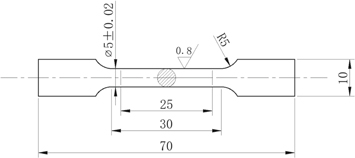
Figure 3. Tensile specimen geometry (all dimensions are given in mm).
Download figure:
Standard image High-resolution imageIntergranular corrosion (IGC) tests were performed according to the ASTM G110-2015 standard [31]. Five specimens were tested, H130, H170, and H250 (heating stage) and C170 and C130 (cooling stage). Electrochemical experiments were performed using an electrochemical instrument (Multi Autolab M204, Metrohm Company, Switzerland). The test specimen was polished to a square surface of 1 cm2 using a 2000 grit SiC paper and used as the working electrode. A saturated calomel electrode and a Pt sheet were used as the reference and counter electrodes, respectively. The anodic and cathodic polarisation curves were acquired from −1.2 to −0.2 V at a scan rate of 1 mV·s−1. The simulated bulk Ω phases (Al2Cu) of the alloy were melted and cast according to their chemical composition. Pure aluminium was simulated as a precipitation-free zone (PFZ). The solution-treated alloy was simulated as the matrix. The open circuit potential was determined at the scan rate of 1 mV·s−1.
The corrosion morphology and maximum corrosion depth were determined by optical microscopy (Leica DM3M, Wetzlar, Germany). Transmission electron microscopy (TEM; Tecnai G2F20, FEI Company, USA) images were obtained at the accelerating voltage of 200 kV. The specimens were mechanically thinned to 50–70 μm using emery papers and then twin-jet electro-polished in a solution of 75% methanol and 25% nitric acid at −25 °C.
3. Results
3.1. Hardness and electrical conductivity
The hardness variation in the alloy during the NIA treatment is presented in figure 4. During the heating stage, the hardness increases rapidly with increasing ageing time, reaching 120 HV at 250 °C. During the cooling stage, the hardness increases gently up to a peak value of 124 HV. The electrical conductivity increases during the heating stage up to 38% IACS at 250 °C. The growth rate decreases during the cooling stage, with the conductivity increasing to a maximum of 40.5% IACS at 170 °C, followed by a decrease to 39.5% IACS at 100 °C. For the T6-treated specimen, the final measured hardness and electrical conductivity were 120 HV and 38% IACS. The electrical conductivity and hardness showed identical trends. This implies that high strength and favourable corrosion resistance can be acquired by NIA treatment.

Figure 4. Hardness and conductivity variations in the alloy during the NIA treatment
Download figure:
Standard image High-resolution image3.2. Mechanical properties
The ultimate tensile strengths (UTSs) of the specimens subjected to different ageing treatments are shown in table 2 and figure 5. The UTS and yield strength (YS) increased with increasing ageing time and exhibited trends similar to those of the hardness. The UTS and YS of the C130 specimen were 395 and 355 MPa, respectively, which were similar to the values obtained for the T6 tempered specimen (400 and 365 MPa, respectively) and alloy B206 (T7 tempered; 400 and 360 MPa [32]). The total ageing time was only 340 min.
Table 2. Mechanical performance of the alloy in different conditions.
| Temper | Yield strength (MPa) | Ultimate tensile strength (MPa) | Elongation (%) |
|---|---|---|---|
| T6 | 365 | 400 | 7.5 |
| H130 | 285 | 290 | 7.0 |
| H170 | 294 | 350 | 6.0 |
| H250 | 340 | 380 | 6.5 |
| C170 | 346 | 385 | 7.0 |
| C130 | 355 | 395 | 8.2 |

Figure 5. Tensile properties variation of the alloy during NIA treatment.
Download figure:
Standard image High-resolution image3.3. Corrosion behaviour
3.3.1. Intergranular corrosion behaviour
Figure 6 shows optical micrographs of the corrosion morphologies and maximum corrosion depths of the specimens. All corrosion cracks grew along the grain boundaries. The corrosion depths were affected by the ageing treatment. The maximum corrosion depth of the H170 specimen was 80 μm, with a relatively distinct network structure. The corrosion resistance of the H250 and C170 specimens were much lower, with maximum depths of 180 μm and 220 μm, respectively. However, the corrosion sensitivity was lower for C130, with a maximum corrosion depth of 165 μm. This indicates that the corrosion sensitivity was reduced during the cooling stage. Thus, the corrosion resistance improved significantly through the NIA treatment in the following order: H170 > C130 > H250 > C170.

Figure 6. Optical microstructure of IGC during NIA process: (a) H170; (b) H250; (c) C170; (d) C130.
Download figure:
Standard image High-resolution image3.3.2. Electrochemical analysis
Figure 7 shows the polarisation curves of the Al–Cu–Zn–Mg alloy specimens subjected to different NIA treatments in 3.5% NaCl IGC solution. These polarization curves involving cathodic and anodic branches exhibited similar shapes. The corrosion current densities were obtained from the polarisation curves by Tafel plots using both cathodic and anodic branches of the polarization curves. The corresponding corrosion potentials (Ecorr) and corrosion current densities (Icorr) are shown in table 3, and they represent the typical electrochemical characteristics of an aluminium alloy system. The negative Ecorr and increased Icorr imply greater vulnerability to corrosion. Ecorr and Icorr varied significantly for the different NIA-treated specimens. During the cooling stage, Icorr decreased further for the C130 specimen, and its Ecorr was larger than that for the C170 specimen. Thus, it can be concluded that the C130 specimen exhibits excellent corrosion resistance.

Figure 7. Polarization curves of the alloy for different specimens.
Download figure:
Standard image High-resolution imageTable 3. Electrochemical parameters of the alloy with different NIA treatments.
| Temper | Ecorr(V) | Icorr(A cm−2) cm−2) |
|---|---|---|
| C130 | −0.6317 | 2.51E-06 |
| C170 | −0.7456 | 4.16E-06 |
| H250 | −0.6459 | 3.01E-06 |
| H170 | −0.6281 | 1.98E-06 |
| H130 | −0.6095 | 1.94E-06 |
3.4. Evolution of precipitates
Bright-field TEM images of the intragrain and grain boundary precipitates are shown in figure 8 with the ageing degree. This figure also shows the corresponding electron diffraction patterns acquired along the [110]Al zone axes. The diffraction pattern of H170 (inset of figure 8(a)) mainly comprises the matrix spots. At this early stage of ageing, no phase had precipitated from the matrix, as shown in the bright-field images in figures 8(a) and (b). In contrast, in the H250 specimen (ageing for 220 min), a small number of fine Ω precipitates appeared non-uniformly in the aluminium matrix (figure 8(c)); unlike the specimens removed during the cooling stage, there were no PFZs near the grain boundaries (figure 8(d)). The weak diffraction spots at the 1/3 and 2/3 {220}α positions corresponded to the Ω phase [33]. As the temperature decreased to 170 °C, numerous fine Ω phases were precipitated in the grain interior (C170; figure 8(e)). Some large precipitates existed along the boundary continuously. The precipitation of solution atoms at grain boundaries typically resulted in the formation of a PFZ (figure 8(f)). The width of the PFZ in the C170 specimen was 252 nm. For the C130 specimen (ageing time up to 340 min), new finer precipitates were formed at the intragrain, which reduced the width of the PFZ to 146 nm, as shown in figures 8(g) and (h).

Figure 8. Intragranular and intergranular TEM images of the alloy during the NIA process recorded close to <110 > :(a), (b) H170; (c), (d) H250; (e), (f) C170; (g), (h) C130.
Download figure:
Standard image High-resolution image4. Discussion
The results obtained in this study indicate that the NIA treatment bestows good corrosion resistance and tensile properties to the Al–Cu–Zn–Mg alloy. The precipitates in the Al–Cu–Zn–Mg alloy comprise large amounts of θ' and Ω phases. The ageing precipitation sequence of the cast alloy was supersaturated solid solution (SSS) → GP zone → Ω phase → θ' phase [12].
Precipitation strengthening was the primary strengthening mechanism for the cast aluminium alloy. Structural characterisation showed that the Ω-phase is the main precipitated phase in the alloy (figure 8). The mechanical strength was dependent on the size and density of the precipitates, which impeded the movement of dislocations in the grain interior. Fine dispersed Ω phases were precipitated in the cooling stage. As the dislocations could pass the Ω phase by cutting them, the strengthening effect could be expressed as [34]:

where f is the volume fraction of the precipitate, r is the radius of the precipitate, and c1, m, and n are constants. The high strength was related to the high volume fraction and large radius of the precipitate particles. Fine Ω phases precipitated when the ageing continued in the cooling stage, as demonstrated by the TEM analysis. By the time the ageing temperature had decreased to 130 °C (∼340 min into the ageing process), the new fine precipitated Ω phases and the previous Ω phases did not significantly coarsen. A higher volume fraction of Ω precipitated in the grain interior, whose radius can be controlled to some degree. Therefore, the specimens were observed to have improved strength.
The experimental potentiodynamic polarization curves for the different conditions are shown in figure 7. It is observed that the corrosion rates were very similar for all the examined specimens. It is well known that the corrosion degree is further dependent on the corrosion rate. Besides, the electrochemical corrosion rate increases linearly with the corrosion current density(Icorr) according to Faraday's law [35]. Low self-corrosion means high galvanic efficiency and the Icorr value is in good agreement with the corrosion rate. According to the section of the polarization curves, compared to C170 sample, the C130 sample showed more positive potential and lower corrosion current density. This indicates that the corrosion resistance of C130 was larger than C170, thereby implying the lower corrosion efficiency. It can be seen that the polarization results were in accordance with the IGC measurements.
As the Ω phases were the predominant precipitates of the Al–4.5Cu–3.5Zn–0.5Mg alloy, the bulk Al–Cu alloy was simulated as an Ω phase. The model was prepared according to the stoichiometry. The grain-boundary area of the alloy includes the matrix, PFZ, and the ageing-precipitation Al2Cu phase. The solution Al–Cu–Zn–Mg alloy was simulated as the matrix. Pure aluminium was simulated as the PFZ because no precipitates exist in the PFZ. The open circuit potentials (figure 9) increased as: EPFZ < EΩ < Ematrix. It is generally considered that the essential thermodynamic requirement for corrosion to occur is Ec − Ea > 0, where the corrosion driving force arises from the difference between the electro-chemical potentials of the cathode (Ec)and the anode (Ea) [36]. The IGC of the alloy is the result of microgalvanic cell action at the grain boundary, which is related to the grain boundary precipitates, PFZ, and the surrounding solid solution aluminium matrix. The effect of the PFZ on corrosion has been reported in many previous studies [19, 37, 38]. Compared to corrosion potentials of the matrix and Al2Cu, the corrosion potential of the PFZ is negative; hence, the PFZ acts as an anodic zone, with the lowest potential, for the Al2Cu phase and the matrix. Thus, it is preferentially corroded. Consequently, the IGC resistance of the alloy is mainly dependent on the microstructure of the PFZ. The H170 specimen had the least IGC sensitivity, as it contained no precipitates in the matrix or at the grain boundary. The H250 specimen had no distinct PFZ, but some precipitates had formed along the grain boundary, as shown in figures 8(c) and (d); the discontinuous distribution of precipitates makes the grain boundaries anodic in nature, which is in contrast with the nature of the matrix and results in the IGC (figure 6(b)). A schematic of this mechanism is presented in figure 10(a). As the ageing process continued, during the cooling stage, the formation and coarsening of precipitates on the grain boundaries led to the formation of a PFZ. In this case, two galvanic couplings can develop, i.e. between the PFZ and matrix, and between the PFZ and grain boundary precipitates. Hence, the IGC of the C170 specimen was the most severe; as it had the widest PFZ, as shown in figure 6(c) and figure 8(f). A schematic of this mechanism is presented in figure 10(b). As the ageing temperature decreased further to 130 °C, the new fine precipitates narrowed the PFZ (figure 8(h)). Narrowing of the PFZ is beneficial for improving corrosion resistance [39]. The precipitates along the grain boundary were discontinuous, thereby impeding corrosion; correspondingly, the degree of IGC was dramatically reduced for the C130 specimen, as shown in figure 6(d). Therefore, it is concluded that high strength and good corrosion resistance can be obtained by the NIA treatment.
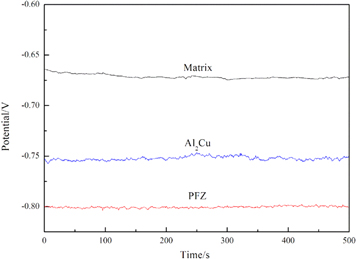
Figure 9. Open circuit potential of the simulated matrix, Al2Cu and PFZ.
Download figure:
Standard image High-resolution image
Figure 10. Schematic illustration of intergranular corrosion.
Download figure:
Standard image High-resolution image
5. Conclusions
The effect of NIA treatment on the strength and corrosion resistance of cast Al–4.5Cu–3.5Zn–0.5Mg alloy was studied. The following can be concluded from this work.
- (1)The hardness and tensile strength of the tested alloy increased up to 124 HV and 395 MPa, respectively, with increasing ageing degree. The electrical conductivity increased in the heating and cooling stages up to 170 °C, then decreased slightly; good IGC resistance and tensile strength were obtained for C130. The electrical conductivity and maximum corrosion depth were 40 % IACS and 165 μm, respectively.
- (2)The corrosion resistance of the alloy was mainly determined by PFZ. The width of the PFZ along the grain boundaries decreased during the cooling stage of the NIA treatment. As the result, the IGC resistance of the alloy decreased as: C130 > C170. Thus, NIA can provide an excellent combination of desirable characteristics (high strength and corrosion resistance) to Al–4.5Cu–3.5Zn–0.5Mg alloys, thereby expanding the applications of such alloys in the equipment manufacturing industry.