

Abstract
Single layer thermal barrier coatings (TBCs) of La2Zr2O7 (LZ) and double layer YSZ/LZ TBCs produced from amorphous (LZA) and crystalline (LZC) feedstock were deposited by atmospheric plasma spray (APS) technique. Thermal cycling behaviors, phase structures and cross-sectional morphologies before and after thermal cycling tests of these coatings were studied in detail. Microstructural properties of three different types of coatings affect thermal cycling lifetime of the coatings. The thermal cyclic test results indicate that the thermal cycling lifetime of LZC/YSZ double layer TBCs is longer than that of single layer LZA and LZC TBCs due to the fact that there are improvements in the sintering resistance ability, thermal expansion mismatch between the ceramic layer and the metallic substrate at high temperature, and thermal insulation effect of DLC (double layer coating) LZ/8YSZ TBCs. The thermal cycling tests indicated that the YSZ/LZC coating has a lifetime of 400 cycles which is longer than single layer LZA and LZC coating. The failure of LZC and LZA coatings mainly results from excessive growth of thermally grown oxide layer, the thermal expansion mismatch between ceramic top coatings and bond coat and thermal stresses accumulated during thermal cycling tests.
Export citation and abstract BibTeX RIS
1. Introduction
Thermal barrier coatings (TBCs) consist of a ceramic layer with low thermal conductivity and high thermal expansion coefficient on the high oxidation resistant metallic bond coat. In many industrial applications, most of the thermal barrier coatings are manufactured by using Y2O3 (yttria) stabilized ZrO2 (YSZ) [1].
However, YSZ coatings are damaged when surface temperature increases to higher than 1200 °C due to volume change associated with phase transformation [1–3]. In addition, sintering of ceramic top coat, TGO formation between top coat-bond coat interface, hot corrosion and CMAS is other damage mechanism for YSZ TBC as reported previous studies [4–9].
Therefore, new thermal barrier coating materials are needed to be operated above temperatures higher than 1200 °C. Up to date, various researchers have studied Pyrochlores, Hexaaluminate, Perovskites, Fluorite, Complex form of ceramic materials for high temperature service conditions as an alternative to YSZ [2, 9–12]. Lanthanum zirconate (LZ), candidate ceramic material for TBC applications, has attracted much interest due to its low thermal conductivity (1.5–1.8 W m−1 K−1 at 1000 °C for a fully dense pellet), high melting point (2280 °C), and high phase stability [10, 11, 13, 14]. Because of thermal expansion coefficient of LZ (9.45 × 10⁻⁶/K in the temperature range of 0 °C–1200 °C for plasma sprayed coating) is much lower than metallic materials, single layer LZ TBCs have poor thermal cyclic lifetime [15, 16]. Therefore, LZ can only be coated on YSZ layer to produce usable TBCs.
For the atmospheric plasma spray process, crystalline, spherical and fine powder (+20/−70 μm) is usually preferred as the feedstock to provide good flowability and deposition efficiency [17]. Fine micro size particles consist of nanosized grains. During the plasma spray process, powder particles transforms to semi molten form when passing through the plasma flame. After transformation, semi molten particles hit the substrate and solidify rapidly. At the end of this process, nanosize grains grow and are distributed randomly [18–20].
Chen et al reported that average grain size distribution of LZ coatings produced by amorphous feedstock (250 nm) is smaller than those produced by crystalline feedstock (450 nm). In addition, thermal conductivity of LZ coating produced by amorphous feedstock is lower than that of coating produced by crystalline feedstock in room temperature. Also, LZ coating produced by amorphous feedstock has a high thermal expansion coefficient compared to the LZ coating produced by crystalline feedstock [18]. High thermal expansion coefficient of coating produced by amorphous powder might reduce thermal expansion mismatch between ceramic top layer and metallic substrate and improve thermal cyclic lifetime of TBCs. In this study, thermal cycling performance of single layer LZ and double layer YSZ/LZC coatings produced using amorphous and crystalline feedstock is investigated in detail.
2. Experimental
2.1. Coating
Inconel 625 disc shaped samples with a diameter of 25.4 mm and thickness of 2 mm, were used as substrate. The chemical composition of inconel 625 substrate is given in table 1. Prior to bond coat production, the substrate was grit blasted using 50–80 mesh alumina particles, in order to remove surface oxides and to improve adhesion of bond coat. Commercial Sulzer Metco Amdry 997 (Ni-23Co-20Cr-8 .5Al-4Ta-0.6Y) powders were used for bond coat production by HVOF.
Table 1. Chemical composition of Inconel 625 substrate.
| Inconel 625 | Ni | Cr | Mo | Fe | Nb | Al | Mn | Other |
|---|---|---|---|---|---|---|---|---|
| Wt% | 63 | 20.6 | 7.9 | 4.3 | 3.2 | 0.4 | 0.2 | 0.4 |
The spray torches (APS and HVOF gun) were fastened on a three-axis CNC table and gun speed was selected as 600 mm min−1. Grit blasted samples were fixed by using clamps on the turntable and turntable speed was selected to be 200 rpm and number of passes was selected as 12. Amdry 997 bond coat powder was used for coating by using Sulzer Metco DJ2700 HVOF gun. HVOF process parameters are listed in table 2.
Table 2. Process parameters of HVOF.
| Material | Pressure (bar) | Flow rate (l/min) | Process | |||||
|---|---|---|---|---|---|---|---|---|
| AMDRY 997 | Oxygen | Propane | Air | Oxygen | Propane | Air | Spray distance (mm) | Powder feed rate (g/min) |
| 10.3 | 6.2 | 7.2 | 11.3 | 18.9 | 23.6 | 250 | 50 | |
Amorphous La-O-Zr powders (Auer-Remy GMBH) produced by chemical co-precipitation synthesis and spray dry method was used for this study. Amorphous La-O-Zr powders of which its La2O3 content was increased approximately 5% [21], were selected as a starting materials for amorphous LZ coating production. Crystalline La2Zr2O7 powder was synthesized by a solid state reaction method. Spray dried amorphous La-O- Zr powders were heat treated at 1400 °C for 4 h. YSZ powder (Metco 204-NS) has been used to produce double layer TBCs.
SEM images of powders are given in figure 1. As it seen in figure 1, Amdry 997 bond coat powder and YSZ powder have spherical morphology. LZA and LZC powders have complex-shaped morphology. LZA and LZC powders are formed by irregular distribution of spherical and angular particles.
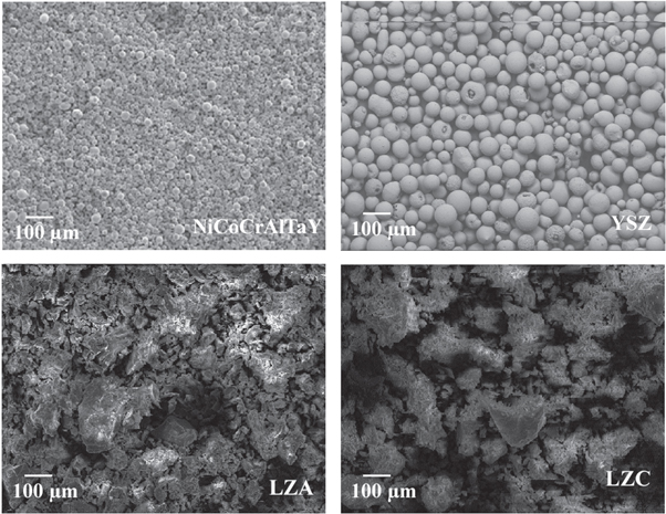
Figure 1. The morphology of powders.
Download figure:
Standard image High-resolution imageFigure 2 shows particle size distribution of powders. After heat treatment, particle size of amorphous powder has increased. Average particle sizes of YSZ, LZA and LZC powders are 65 μm, 89 μm and 120 μm respectively.

Figure 2. Particle size distribution of powders.
Download figure:
Standard image High-resolution imageLZA, LZC and YSZ buffer layer ceramic coatings were produced by air plasma spray (APS) method by using Sulzer Metco 9 MB plasma spray gun. Gun nozzle is a commercial 730 C and powder injection angle was placed perpendicular to plasma flame. Process parameters of plasma spray technique are listed in table 3.
Table 3. Process parameters of plasma spray.
| Parameters | |
|---|---|
| Current (A) | 500 |
| Voltage (V) | 65 |
| Primary gas,Ar (l/min) | 42.5 |
| Secondary gas, H2 (l/min) | 7 |
| Carrier gas flow rate, Ar (l/min) | 6.4 |
| Powder Feed Rate (gr/min) | 40 |
| Number of passes | 12 |
| Spray distance (mm) | 75 |
| Gun speed (mm/min) | 200 |
| Turntable speed (rpm) | 100 |
2.2. Thermal cycle tests
Thermal cycling tests were carried out on a burner-rig facility with a propane + oxygen flame. The sample surface was heated from room temperature to 1200 ± 50 °C in 1 min followed by a cool down process within 1 min using a compressed air jet. The cycling process was repeated until 50% of the ceramic coating area was spalled. Schematic representation of thermal cycle test facility is illustrated in figure 3.

Figure 3. Schematic illustration of thermal cycle test facility.
Download figure:
Standard image High-resolution image2.3. Microstructural characterization
The microstructure, morphology and chemical composition of the coatings taken from cross section were examined by field emission electron microscopy (JEOL JSM 7000F) which is equipped with EDS. X-ray diffraction (Rigaku Miniflex) was used to determine the crystalline structure of the powder and coatings before and after the thermal cycle tests. In order to analyze grain size of TBCs, coating surface was thermally etched by using laser. Average grain size of TBCs were determined by intercept method.
3. Results and discussion
Figure 4 shows photograph of two different TBC samples. The samples produced from amorphous powders have a lower surface roughness than samples produced from crystalline powders. This implies that amorphous and crystalline powders have a different particle size distribution. The feedstock powder with coarser particle does not easily melt due to the nature of APS process. This affects TBCs microstructure strongly in terms of porosity size, pore distribution and intersplats crack density [22, 23].
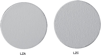
Figure 4. Surface photograph of LZ TBCs by using amorphous and crystalline powder as a feedstock.
Download figure:
Standard image High-resolution imageHeat treated amorphous powders transform into crystalline form and particle size increases as a result of sintering [10, 19]. Crystalline powder is again subjected to heat treatment when passing through plasma flame and transform into semi-molten form. These half molten particles travel through a spray distance and accumulate by bonding at the substrate surface. On the substrate, each molten particle is formed during solidification. The particles grow to form granules during solidification.
Firstly, amorphous powder particles are heat treated while they were passing through plasma flame. As a result of this heat treatment in plasma flame, amorphous powder transforms crystalline form and fine grains begin to form [18].
Figure 5 shows cross-sectional SEM images of two types of TBCs. Top coat thickneses of LZA and LZC TBCs are observed to be 250 μm approximately. The microstructure of top coats prepared by crystalline (figures 5(b) and (d)) and amorphous powder (figures 5(a) and (c)) are relatively porous, which are often observed in plasma sprayed coatings [24]. There are relatively large defects such as global, large pores LZC TBCs. However, pores distribution is low in matrix compared to LZA TBCs. In addition, LZA TBCs have smaller pores than LZC coatings and pore distribution is very high. Percentage of porosity is found to be close to each other in two type of TBCs. Percentage of porosity was determined by an image analysis software ImageJ. Porosity levels of the coatings are given in table 4. As it seen in table 4, because of the sintering effect, the porosity level of the coatings have decreased after the thermal cycle.
Table 4. Porosity levels of the coatings.
| Specimen | Porosity % | |
|---|---|---|
| Before thermal cycle | After thermal cycle | |
| LZA | 16 | 8.9 |
| LZC | 26.4 | 12 |
| DLCLZ | 21.6 | 18 |
| DLC-LZ layer | 17 | 12 |
| DLC-YSZ layer | 26 | 22 |

Figure 5. Cross sectional micrographs of LZA(a, c) and LZC(b, d) TBCs.
Download figure:
Standard image High-resolution imageRegions highlighted by a rectangular frame on figure 5 are shown to be intersplat cracks and voids. It can be seen that intersplat border of LZC TBCs are very distinct. LZA TBCs have less intersplats cracks and voids than LZC TBCs. Also, intersplat crack size of LZA TBCs are very short compared to intersplats crack size of LZC TBCs. Thus, different sintering and solidification behaviours of two type feedstock result in different microstructures. This strongly affected thermal cycling lifetime of TBCs in parallel with thermal expansion behaviour and thermal conductivity [3, 7, 25].
XRD patterns of amorf and crystalline LZ powder shown in figures 6(a) and 7(a) respectively. As expected, crystalline peak is not observed in XRD results of amorphous LZ powder. peaks of defect fluorite structure phase is seen in crystalline LZ powder. Amorphous powder transformed to crystalline phase after the heat treatment process. Figures 6(b), 7(b), 8(a) show XRD pattern of sprayed LZA, LZC and double layer YSZ/LZC TBCs before thermal cycle tests. Three type of TBCs are formed in crystalline form. All diffraction patterns belong to La2Zr2O7 defect fluorite structure (Card no: 080–0471) because of the absence of the four additional diffraction peaks in the 2θ range 14°–45° in its XRD pattern compared to that of A2B2O7 pyrochlore structure (Card no: 073-0444) [26–28]. But, previous studies show that pyrochlore and fluorite structure rare earth zirconate have similar thermophysical properties [29]. After spraying crystalline La2Zr2O7 powder, this phase transformation could not be observed, but peak intensity of TBCs gets higher than that of crystalline powders. On the other hand, LZA TBCs have a lower peak intensity than LZC TBCs due to the excess amorphous phase in the structure after plasma spraying.

Figure 6. Grain structure of LZA and LZC TBCs.
Download figure:
Standard image High-resolution image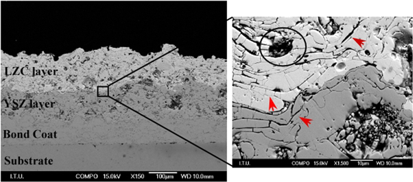
Figure 7. Cross sectional micrographs of YSZ/LZC double layer TBCs.
Download figure:
Standard image High-resolution image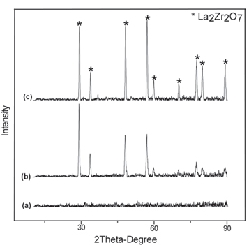
Figure 8. XRD patterns of (a) amorphous powder, (b) LZA TBCs, (c) LZA TBCs after thermal cycle test.
Download figure:
Standard image High-resolution imageFigure 9 shows grain structure of coatings after thermal etch. LZA coating have finer grains than LZC coating. Average grain size of LZA and LZC coatings calculated 160 nm and 450 nm respectively. This values close to values reported by Chen et al [18].
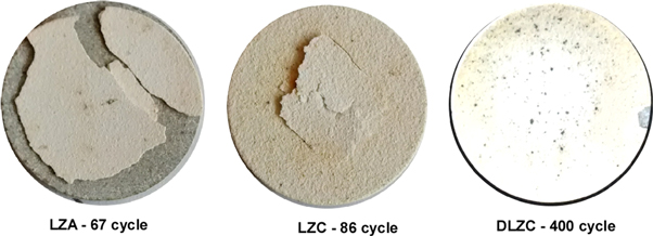
Figure 9. Photograph of TBCs samples after thermal cycling tests.
Download figure:
Standard image High-resolution imageFigure 10 shows cross-sectional SEM images of YSZ/LZC double layer TBCs. As can be seen that thicknesses of bond coat, YSZ layer, and LZ layer are about 100 μm, 100 μm, and 120 μm respectively. The double layer coating also has the traditional thermal barrier coating microstructure which contains porosities and intersplat cracks [30, 31]. When the transition zone between YSZ and LZ layers is examined, it is seen that the adhesion between the two layers is continuous.

Figure 10. Cross sectional scanning electron micrographs of LZA(a), (b) and LZC(c), (d) TBCs after thermal cycle tests.
Download figure:
Standard image High-resolution imageFigure 11 shows surface photographs of LZA and LZC TBCs after thermal cycling tests. Thermal cycling lifetime of LZA TBCs was lower than LZC TBCS. LZA TBC has completely damaged completely on the top coat after 67 cycles. There wasn't any damage observed on the top coat until 66 cycles for the LZC TBC, but, in the 67th cycle firstly a crack appeared in the middle region of the top coat. Then crack propagated further during thermal cycling test and this region spalled in 86th cycle. The difference between LZA and LZC TBCs thermal cyclic lifetime is based on the previously described microstructural differences. Different porosity and intersplat sizes and their distribution are quite effective in this situation. According to the finite element analysis from different studies, it is found that stress concentration often located at the position of the defects, porosities and intersplat cracks. High porosity and intersplat crack distribution result in high stress acumulation in the top coat. [32]. In addition, large pores and large intersplat crack size tolerate thermal expansion mismatch stress and improve thermal durability of TBCs [33].

Figure 11. Cross sectional scanning electron micrographs of YSZ/LZC double layer TBCs after thermal cycle tests.
Download figure:
Standard image High-resolution imageAt the end of the 400th cycle, double layer LZ/YSZ TBCs has not been damaged. The results of this thermal cycle tests are consistent with previous works [31, 34]. YSZ buffer layer tolerated thermal expansion mismatch between LZ layer and bond coat which leads to high thermal stress. This leads to good performance of thermal cycling in double layer YSZ/LZ coating.
Calculations from previous studies about double layer LZ/YSZ coatings made with finite element method are also compatible with these explanations [35–37]. The residual stress level in the ceramic top layer also affects the thermal cycle life. According to the calculations made by the finite element method it is found that the DCL LZ/8YSZ has lower residual stress compared with that of the single ceramic layer 8YSZ [32].
Figure 12 shows cross sectional SEM images of two types of TBCs after thermal cycling tests. It is observed that, after the thermal cycling tests the spallings of coatings are similar for two type TBCs. There is a complete delamination at the top coat, near the top coat-bond coat interface. Because of the sintering effect, the porosity level of the LZA and LZC coatings but also size of intersplat cracks have decreased after the thermal cycle test. Some significant intersplat cracks are marked with an arrow mark. It is seen that there is a more significant intersplat crack structure in the LZC coating than LZA coating. Porosities and intersplat crack size and distribution decrease as a result of sintering effect. Some distinctive intersplat cracks marked with arrows. LZC coating have more distictive intersplat crack than LZA coating .
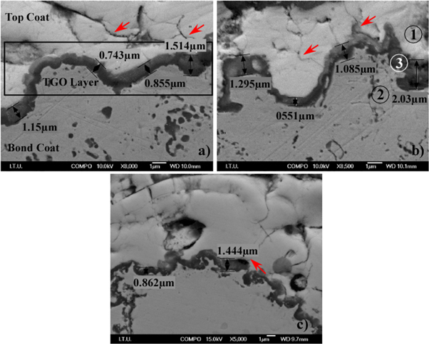
Figure 12. TGO microstructure of TBCs, (a) LZA, (b) LZC, (c) YSZ/LZC.
Download figure:
Standard image High-resolution imageFigure 13 shows cross sectional SEM images of doube layer TBCs after termal cycle test. LZC top coat microstructural properties similar to initial microstructure. Intersplat cracks and porosities of doube layer TBC are still distinctive compared to single layer coating. Unlike the single layer, it appears that after 400 thermal cycles pore and splat structure of the YSZ buffer layer are similar to the initial microstructure. Since the LZ has a low thermal conductivity, it keeps the YSZ layer at lower temperatures during the thermal cycle. Therefore YSZ buffer layer can keep its initial microstructure longer but after a long time it starts sintering [31]. Initial microstructure of TBCs shows that both TBCs after thermal cycling tests and vertical crack occurred at the cross section of LZA coatings. This vertical crack is shown with a surrounded rectangle in figure 12.
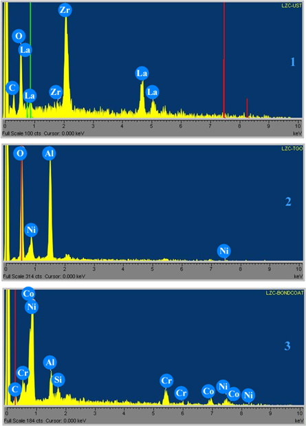
Figure 13. EDS results from points 1, 2, 3 in figure 12.
Download figure:
Standard image High-resolution imageCorrosion of TBCs microstructure is not the main failure mechanism for the LZA and LZC coating. Thermal stress between bond coat and ceramic top coat plays an important role in crack formation and progress. If the stress accumulated exceeds the adhesive and cohesive adhesion strength of the coating, separation and damage will occur in the coating [38]. Since thermal expansion mismatch is higher, the thermal stress accumulated in single layer coating is higher than the thermal stress accumulated in double layer coating. In addition, YSZ has higher fracture toughness when compared to LZ-based coatings [39]. Thus, this significantly affects crack formation and progress as a result of the thermal stress accumulated in ceramic top coat-bond coat interface [40]. Figure 14 shows the interface zone between bond coats and top coats. TGO layers have grown uninterruptibly at the interface of bond coats and top coats with a thickness of 0.7–2 μm. When coatings are spalled, substrates lose their thermal insulation so, this accelerates forming of Al2O3 and some mixed oxides (spinel oxides, NiO, Cr2O3 etc) at the top coat-bond coat interface [8]. TGO thicknesses of all coatings are found similar even though single layer LZA and LZC coatings are spalled much earlier than double layer coating. However, coatings were not spalled but top coat-TGO failure was totally from interface zone. TGO growth and thermal expansion mismatch between the top coat and substrate caused a formation of very fine vertical micro cracks propagating in the inner layer of top coats and this cracks accelerated the delamination to inner zone of top coat [3, 7, 8, 41].
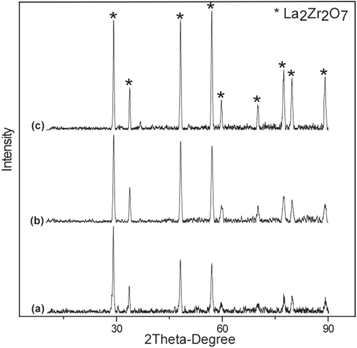
Figure 14. XRD patterns of (a) LZ crystalline powder, (b) LZC TBCs, (c) LZC TBCs after thermal cycle test.
Download figure:
Standard image High-resolution image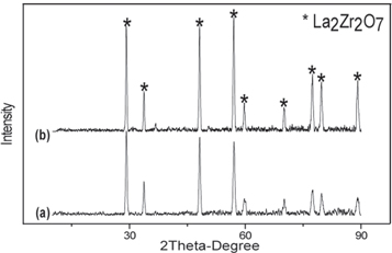
Figure 15. XRD patterns of (a)YSZ/LZC TBCs, (b) YSZ/LZC TBCs after thermal cycle test.
Download figure:
Standard image High-resolution image
The position of these very fine vertical microcracks is very important. According to the finite element analysis for TGO zone, maximum tensile stress is located at the peak of the TGO layer and near to the bond-coat, while the maximum compressive stress is located at the intermediate position of the peak to the valley or valley to the peak. The relative compressive stress has its maximum value, if projection of the vertical crack is in the middle of the peak and valley positions of TGO layer. If these micro cracks are located at the peak of the TGO layer, the vertical crack can partially release the stress concentration around the TGO layer compared with the horizontal crack. This horizontal cracks proceeds through the coating and cause the coating to separate [42].
EDS analysis performed on the point of number 1, 2 and 3 as seen in figure 13 shows EDS results for the marked three point. The point number 2, the TGO layer was mainly composed of Al2O3 and slight Ni [7, 8, 41].
Figures 6(c), 7(c) and 8(b) show XRD patterns of LZA, LZC and double layer YSZ/LZC TBCs respectively after thermal cycle tests. There is no observed phase transformation for the three types of TBCs following thermal cycling test. Three types of TBCs have fluorite peaks as in the TBCs, but peak intensity of TBCs increases after thermal cycling tests [27, 28].
4. Conclusions
In the present study, thermal cycling behavior and failure mechanism of the La2Zr2O7 TBCs produced from amorphous and crystalline powder have been studied. Coatings which are produced from crystalline powder have a higher thermal cycling lifetime than coatings produced from amorphous feedstock. Low intersplat crack density and size caused an early damage in the LZA TBCs. High intersplat crack density and size reduced inner stresses due to thermal expansion mismatch. For this reason, LZA coatings were spalled entire surface of TBCs. However, LZC coatings were spalled only in middle region of the TBCs surface. The spallation of the coatings are due to the effect of thermal expansion mismatch and thermal stress produced during thermal cycling. The oxidation of the bond coat and sintering of the top coat are the factors for the damage. In addition, thermal expansion mismatch accelerates the spallation process. The low thermal cycling performance of single layer coatings produced with two different powders limits the usability of these coatings. However, YSZ/LZC double layer coatings have reached a higher number of thermal cycles and double layer coatings are more usable than single layer coatings.