

Abstract
In this study corrosion behavior of TIG welded 316L stainless steel plates in simulated biological solutions is investigated. The mechanical testing results showed slight decrease in ductility after welding and the fracture surface represented mixed cleavage and inclusions containing dimple structure. The heat affected and weld zone (WZ) demonstrated higher corrosion potential and relatively large pitting tendency than base metal (BM) in both Hank's and Ringer's solution. The formation of delta (δ) ferrite in the heat affected and WZ decreased the corrosion resistance as confirmed from potentiodynamic Tafel scans. The decrease in pitting resistance and lower protection tendency of the WZ compared to BM and heat affected zone was also quantified from the cyclic polarization trends.
Export citation and abstract BibTeX RIS
1. Introduction
Stainless steel, Co–Cr, Ni–Cr and titanium based alloys are widely used in orthopedics as implants materials due to their good mechanical properties, chemical stability in the biological environments and low cost [1–3]. The biological environment is composed of water, dissolved oxygen, salts, organic compounds and complex amino acid structure. These ingredients could affect the functionality of bio-implants adversely if the surface of the implant has structural and design defects. Therefore fabrication, effective post treatment procedures, and excellent surgical practice could enhance the longevity of the implant materials. Stainless Steel AISI 316L is one of the most commonly used material in the orthopedics due to its economical fabrication, good mechanical properties [3, 4] and inherent tendency to form compact and self-healing passive film in the oxidizing environments [1]. The functionality of the surrounding tissues may also be adversely affected due to the release of nickel and chromium ions exceeding tolerance limits. These ions could initiate toxic, allergic or carcinogenic reactions in the surrounding tissues and may sometimes be life threatening [5].
Various components of the metallic implants are joined through welding which could introduce metallurgical defects if the quality procedures are not employed. Although austenitic stainless steels have good weldability but thermal spikes during welding may alter microstructure which could influence the mechanical and electrochemical properties. Also the inherent compositional and microstructural variation in the weld and thermally affected zone could also change the electrochemical behavior of the alloys [6, 7]. Prosthetic devices e. g. mono-bloc hip stems are made of stainless steel and are welded not because of fixation requirements but due to technical and commercial needs [8, 9]. These devices are designed to stay in the body for long periods and any manufacturing defect could lead to premature failure. This scenario is always painful and risky for a patient and requires definite repetitive post-surgical procedures [10]. The aggressive nature of body environment and formation of electrochemical cells at the tissue implant interface could accelerate the localized corrosion reactions [11].
The objective of this study was to determine the effect of welding on the microstructural variation and mechanical properties of the AISI 316L. Also the electrochemical behavior of base metal (BM), heat affected and weld zone (WZ) was examined in the simulated physiological environment i.e. Ringer's and Hank's solutions at ambient temperature.
2. Materials and methods
Two plates of 316L austenitic stainless steels (152.4 mm × 152.4 mm × 4.5 mm) were degreased in a soap solution followed by cleaning in acetone. Weld joint was prepared by beveling the edge of one plate to single 'V' shape with an included angle of 45°. These plates were then welded by Tungsten Inert Gas (TIG) technique using 99.95% pure Argon to prevent oxidation of weld pool. The 3 mm diameter wire (AWS-A5.9ER316) was used as a filler to make a Butt joint. The composition of BM, filler wire and welding parameters are given in tables 1 and 2 respectively.
Table 1. Chemical composition of the base metal (316L) stainless steel and weld filler metal (in wt%).
| Material | C | Mn | Cr | Ni | Mo | P | S | Fe |
|---|---|---|---|---|---|---|---|---|
| Base metal | 0.025 | 1.20 | 16.74 | 9.37 | 2.28 | 0.065 | 0.062 | Bal. |
| Filler metal | 0.022 | 1.35 | 17.00 | 11.52 | 2.10 | 0.031 | 0.014 | Bal. |
Table 2. The parameter used in TIG welding process to join two plates of 316L stainless steel.
| Material | Welding method | Filler material | Diameter of filler materials (mm) | Welding current (A) | Welding Groove | Welding inert gas |
|---|---|---|---|---|---|---|
| 316L | TIG | AWS A5.9ER316 | 3 | 150 | 'V' | Argon |
The three samples for tensile testing were wire cut as per standard (ASTM E8-03) and 1 cm2 samples for metallography were sectioned from each zone i.e. BM, thermally/heat affected zone (HAZ), and WZ. The schematic diagram of the welded plate is shown in figure 1 which describes the location of each sample cut from the BM, HAZ and WZ for microstructural, mechanical and electrochemical analyses. The fracture surface after tensile testing was examined through scanning electron microscope (SEM). For microstructural study one surface from each zone was ground using silicon carbide papers up to 1200 grit size. Final polishing was done with 1 μm diamond paste in order to produce scratch-free mirror-finished surface. The samples were degreased with acetone and washed with alkaline solution followed by rinsing in the distilled water. These samples were etched in a solution containing 3 parts hydrochloric acid (HCl), 2 parts glycerol and 1 part of nitric acid (HNO3) to reveal the microstructural details through optical microscope.
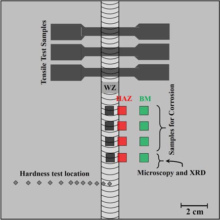
Figure 1. Schematic diagram of the welded plate showing the location of samples cut for mechanical, microstructural and electrochemical testing.
Download figure:
Standard image High-resolution imageThe microstructure and variation in the chemical composition of the WZ was examined through SEM and energy dispersive x-ray (EDX) analysis, respectively. X-ray diffraction (XRD) patterns of BM and WZ were also obtained by using Cu Kα1 (λ = 1.5405 A°) as radiation source. The hardness of the welded joint was determined across the weld line according to ASTM E18-03 standard to elaborate the microstructural features.
For electrochemical analysis; working electrodes (1.44 cm2) from BM, HAZ and WZ were ground to 1000 grit followed by soldering a glass encased copper wire at the back of each specimen. These were then cold mounted in a polyester resin by exposing one surface to the physiological solutions at room temperature. The chemical composition of both physiological solutions i.e. Ringer's and Hank's is given in table 3.
Table 3. Compositions of the physiological solutions (in g l−1).
| Components | Hank's solution pH = 7.4 | Ringer's solution pH = 7.0 |
|---|---|---|
| NaCl | 8.00 | 8.5 |
| KCl | 0.40 | 0.2 |
| CaCl2 | 0.14 | 0.2 |
| NaHCO3 | 0.35 | 0.2 |
| MgSO4.7H2O | 0.06 | — |
| MgCl2.6H2O | 0.10 | — |
| KH2PO4 | 0.06 | — |
| Glucose | 1.00 | — |
Potentiodynamic Tafel scan and cyclic polarization (CP) test methods were used to investigate the corrosion kinetics, passive behavior and pitting tendency of each zone in these solutions. Saturated Calomel was used as reference and compacted graphite rod was used as counter electrode in a three electrode cell system connected with Gamry Potentiostat (PC14-750). All the experiments were repeated three times and the average value of each parameter is given in this study.
3. Results and discussion
3.1. Microstructural study of weldment
The microstructural features of BM, HAZ and WZ depend on the thermal excursion during welding process. The BM represented the relatively finer grains of austenite (γ-phase), represented as 'A' in figure 2(a) compared to austenite in the HAZ (figure 2(b)) near fusion line. This behavior was attributed to the recrystallization of grain structure during thermal excursion. The pseudo-equilibrium conditions during welding, the heating and cooling cycle also resulted in the formation of delta (δ) ferrite phase designated as 'F'. In BM, HAZ and WZ the δ-ferrite phase was elongated within the austenite matrix (γ) depicting the direction of heat flow. However, the concentration of δ-ferrite was higher in WZ than BM and HAZ as shown in figure 2(c). The rapid cooling of WZ during welding cycle restricted the complete peritectic transformation of δ-ferrite into austenite (γ) [12]. The solidification of WZ followed the [L → L + δ → L + δ + γ → γ + δ] sequence representing the nucleation of δ-ferrite in the liquid (L) weld metal followed by the transformation of L-phase into the austenite (γ). The γ-phase formation in the WZ followed the nucleation of δ-ferrite during rapid solidification of the molten metal in the weld pool. To further elaborate the existence of δ-ferrite in the γ-phase, the high resolution image of WZ is shown in figure 3(a). Due to non-equilibrium cooling conditions in the WZ and heterogeneous solid-state phase transformation, the complete conversion of δ-ferrite into γ-phase was limited. By comparing the variation of alloying elements i.e. Cr, Ni, Mn and Mo concentrations in the δ-ferrite and γ-phase, it is possible to predict reason of δ-ferrite formation in the WZ. It was determined that the concentration of ferrite stabilizing elements i.e. Cr and Mo was low in the δ-ferrite compared to γ-phase as given in the table of figure 3. This could possibly be related with the hindered diffusion of these elements from the molten metal in the weld pool to the δ-ferrite nuclei during transient welding conditions.
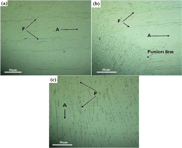
Figure 2. Optical micrograph of AISI 316L weldment showing the distribution of δ-ferrite in the (a) BM (b) HAZ and (c) WZ.
Download figure:
Standard image High-resolution image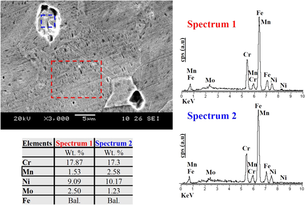
Figure 3. SEM and EDX analysis of the austenitic matrix and ferrite phases (δ-ferrite) in the WZ.
Download figure:
Standard image High-resolution imageAlso, the δ-ferrite in the WZ had acute angle to the ferrite in the HAZ and BM across the fusion line. This could be simulated with the swirling motion of molten weld pool due to arc striking and its forward motion along the weld line.
The formation of δ-ferrite could deleteriously affect the mechanical and electrochemical properties of stainless steel. The higher concentration of δ-ferrite could disrupt the formation of uniform passive film over the austenitic matrix (A) resulting in the initiation of localized corrosion reactions [13, 14]. In other way the existence of δ-ferrite in the WZ would be advantageous to minimize hot cracking tendency during solidification [15].
The presence of δ-ferrite in the austenite matrix (in WZ) was further confirmed from XRD patterns. Figure 4 represents the diffraction pattern of BM and WZ. The broad peaks originated at 47.4° and 64.8° in the diffraction pattern of WZ corresponded to the (110) and (200) planes of δ-ferrite. On the other hand the peaks affiliated with the austenite (γ) were centered at 2θ = 43.2°, 50.5° and 74.8° which represented the (111), (200) and (220) crystallographic planes, respectively of the matrix phase. The evidence of other Ni and Mn rich phase (i.e. Ni2Mn3Si) peaks in the XRD pattern of WZ also supported the relatively high concentration of these elements in δ-ferrite as confirmed by the EDX analysis (figure 3).
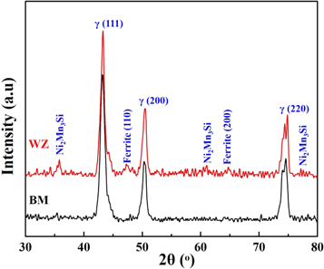
Figure 4. X-ray diffraction patterns of the base metal (BM) and weld zone (WZ).
Download figure:
Standard image High-resolution image3.2. Mechanical testing and fractography
The hardness profile of the weldment from BM to WZ is shown in figure 5. It is represented that the average Rockwell Hardness of BM was 78.5 ± 0.3 HRB which gradually increased to 83.3 ± 0.5 HRB at the fusion line. In the center of WZ the hardness was much higher (85.3 ± 0.5 HRB) than in the HAZ and BM. The increase in hardness was related with the high concentration of δ-ferrite in the austenite matrix [8]. As δ-ferrite (BCC phase) was non-coherent with the γ-matrix (FCC) and may increase the hardness in HAZ and WZ compared to BM.
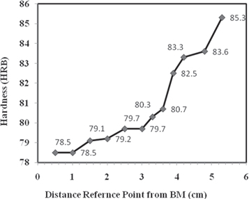
Figure 5. Hardness profile of AISI 316 weldment 5.3 cm away from weld center line.
Download figure:
Standard image High-resolution imageThe tensile testing of welded specimens was carried out in triplicate by using Instron 1120 universal testing machine. The decrease in the ductility of welded sample than 316L (BM only, without welding) was attributed to non-homogeneity in the microstructure (existence of δ-ferrite) which resulted in the fracture of tensile sample from WZ. The welded AISI 316L samples showed relatively higher hardness, yield strength (YS) and ultimate tensile strength than BM but these values were comparable to the filler metal (AWS A5.22 E316) properties as tabulated in table 4.
Table 4. Mechanical properties of the 316L weldment.
| Samples | Yield strength (MPa) | Tensile strength (MPa) | % Elongation |
|---|---|---|---|
| Welded sample | 377.842 ± 5.0 | 525.095 ± 4.0 | 30 ± 1.0 |
| AWSA5.22 E316 | 400 | 560 | 35 |
The 30% elongation of welded 316L samples before fracture was lower than un-welded AISI 316L (40%) steel and for comparison, it is recommended to see [16]. The fracture surface showed typical ductile dimple like structure mostly formed by the coalescence of micro voids originated at the inclusions as evident in figure 6.
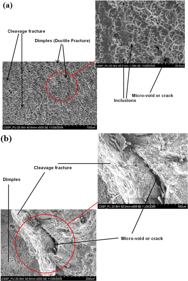
Figure 6. SEM images of fractured surface after tensile testing (a) ductile dimple structure (b) mixed mode fracture (dimple + cleavage).
Download figure:
Standard image High-resolution imageThe shallow shear tongue of dimples corresponded to the increase in hardness after welding which was also in support with low percentage elongation. It was noticed that some intergranular micro-cracks were present around the carbide precipitates within the WZ. The existence of transgranular crack along the crystallographic planes may produce cleavage facets along with dimple morphology as evident in figure 6(b). The mixed mode of fracture behavior through the WZ was attributed to the formation of non-coherent δ-ferrite in the austenitic matrix. The presence of second phase within the microstructure also validated the coalescence of micro-voids leading to final fracture due to segregation of δ-ferrite along the grain boundaries during rapid cooling of molten metal in the weld pool.
The composite (δ + γ) microstructure of WZ may also result in the decrease in ductility than the AISI 316L un-welded material. It was deduced that non-equilibrium thermal fluctuations and cooling affected the mechanical properties of the welded AISI 316L. This behavior was related with the presence of large concentration of δ-ferrite and other phases in the WZ.
3.3. Electrochemical investigation of weldments
3.3.1. Open circuit potential (OCP)
The OCP of BM, HAZ and WZ in both Ringer's and Hank's solutions was determined with respect to Saturated calomel (SCE) reference electrode (+250 mV versus SHE) as given in table 5. It was observed that OCP of BM, HAZ and WZ in Ringer's solution was more negative than in Hank's solution. This was attributed to the high chloride contents in the Ringer's solution, which may possibly decrease the OCP compared to Hank's solution. At pH (7.4 ± 0.1) the stable species i.e.  and
and  in the hanks solution have the ability to preferentially interact with the surface of stainless steel. These species could promote the stability of passive film over the surface and may limit the localized corrosion tendency of 316L stainless steel [1, 6]. The relatively negative OCP value of HAZ in Ringer's solution was considered due to the recrystallization of γ-phase and nucleation of δ-ferrite along the grain boundaries. These sites could be the active sites for electrochemical attack at the surface. Both HAZ and WZ were found to be more anodic (negative OCP) compared to the BM in Hank's solution whereas, thermodynamically the HAZ was more active than BM and WZ in the Ringer's solution.
Table 5. Open circuit potential (OCP) in both physiological solutions.
| Samples | BM | HAZ | WZ |
|---|---|---|---|
| Hank's Solution | |||
| OCP (mV) | −139.3 ± 5 | −292.09 ± 8 | −220.09 ± 7 |
| Ringer's Solution | |||
| OCP (mV) | −234.75 ± 7 | −368.33 ± 8 | −239.25 ± 10 |
3.3.2. Potentiodynamic polarization scans
Typical Potentiodynamic Tafel Scans for BM, HAZ and WZ were obtained (figure 7) in both simulated physiological solutions. The polarization behavior was evaluated in the potential range of (−0.5 to 1.5 V)OCP with a scan rate of 1 mV s−1. The kinetic parameters of BM, HAZ and WZ were calculated by Tafel extrapolation method using Echem Analyst software as given in table 6. The higher corrosion current density (Icorr) of HAZ and WZ in ringer solution represented higher corrosion rate compared to BM according to Butler–Volmer relation [17].

where ' ' and '
 ' are the anodic and cathodic Tafel constants. '
 ' and '
 ' represent the anodic and cathodic polarization of the metal surfaces during Tafel extrapolation.
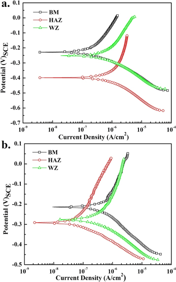
Figure 7. Potentiodynamic polarization scans (a) Ringer's (b) Hank's solutions.
Download figure:
Standard image High-resolution imageTable 6. Potentiodynamic Tafel scans extrapolation parameters.
| Samples | βa (mV/decade) | βc (mV/decade) | Icorr (μ A cm−2) | Ecorr (mV) | Corrosion rate (mpy) |
|---|---|---|---|---|---|
| Ringer's Solution | |||||
| BM | 298.5 | 93.50 | 0.241 ± 0.01 | −228.0 ± 10 | 0.104 ± 0.04 |
| HAZ | 1876 | 217.6 | 2.53 ± 0.02 | −398.0 ± 6 | 1.102 ± 0.05 |
| WZ | 1745 | 149.3 | 2.15 ± 0.05 | −275.0 ± 8 | 0.934 ± 0.04 |
| Hank's Solution | |||||
| BM | 219.4 | 72.70 | 0.0715 ± 0.005 | −187.0 ± 6 | 0.031 ± 0.006 |
| HAZ | 253.5 | 82.6 | 0.0842 ± 0.004 | −292.0 ± 9 | 0.036 ± 0.002 |
| WZ | 349.9 | 120.2 | 0.450 ± 0.008 | −277.0 ± 12 | 0.195 ± 0.02 |
The presence of δ-ferrite in the austenitic matrix could disrupt the uniformity of passive film. The preferential dissolution of δ-ferrite caused by the formation of local galvanic cells within the austenitic matrix could enhance the pitting tendency of surface in the chloride containing physiological solution. The higher Icorr and more negative (active) corrosion potential Ecorr of HAZ than BM in the Ringer's solution was also attributed to the formation microstructural inhomogeneity during welding process. The WZ zone also presented high corrosion rate than BM in the same solution and was related with the relatively high concentration of dispersed δ-ferrite in the austenitic phase. However, under steady state condition (at or near OCP), the relative small difference in the Ecorr of WZ (−275.0 mV)SCE and BM (−228.9 mV)SCE may be less deleterious in terms of local galvanic cell formation.
In Hank's solution the corrosion rate of WZ was relatively high and followed the trend (corrosion rate of BM < HAZ < WZ). In comparison, the corrosion rate of AISI 316L weldment (of all BM, HAZ and WZ) in the Ringer's solution was higher than in Hank's solution. The lower corrosion rate in Hank's solution may be related with the adsorption of stable species (
 ) at the local anodic sites developed at the surface under applied conditions. These adsorbed anions may restrict the de-polarization of surface and hence may decrease the ingress of other aggressive ions towards the surface. In relation with adsorption, the electrochemical stability of the passive film was enhanced and therefore decreased the corrosion tendency of weldment in Hank's solution. But the relatively high concentration of δ-ferrite in the WZ within and along the grain boundaries could disrupt the uniformity of the passive film, which could be the possible reason of high corrosion rate in both solutions. The reported results about the electrochemical behavior of are in support and comparable to other electrochemical investigations on literature austenitic steel welded joints [12, 18–20]. To evaluate the passivation tendency of different zones in the Ringer's solution, the each sample was polarized from its OCP to +1.5 V (versus OCP) with a scan rate of 5 mV s−1. The passive current density (ip) of HAZ was 35.93 μA cm−2 compared to 13.80 and 15.05 μA cm−2 for BM and WZ, respectively. Similarly in the Hank's solution, the ip for HAZ (11.03 μA cm−2) was slightly higher than BM (9.59 μA cm−2) but WZ presented no limiting current value (representing passive behavior). The continuous increase in the current density during anodic polarization was associated with formation of relatively unstable passive film due to presence of large concentration δ-ferrite in the γ matrix.
3.3.3. CP characterization
During CP the surface of all samples was scanned between −0.5 mV/OCP to an apex potential (1.00 V versus OCP). The pitting resistance and protection tendency was measured by reversing the potential from the apex potential at a scan rate of 2.5 mV s−1. The abrupt increase in the current during forward (anodic) scan belongs to the transpassive region corresponding to the breakdown of passive film, designated as pitting potential, Epit. The intersection of reverse polarization curve with the anodic polarization line resulted in the positive hysteresis loop, represented the pitting tendency and is designated as protection potentials, Eprot. In other words, the pitting may happen above Eprot and can be used as a diagnostic to estimate complete protection of surface from localized attack under applied conditions. There is always a possibility for the formation of metastable pits above this potential which are difficult to analyze by other physical characterization means. However, the potential larger than Epit represents the formation of stable pits at the surface.
The CP scans of all the samples are shown in figure 8 and the values of corrosion potential, (Ecorr) pitting potential (Epit) and protection potential (Eprot) are given in table 7.
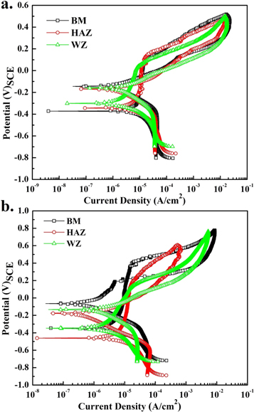
Figure 8. Cyclic polarization scans for AISI 316L (a) in Ringer's (b) Hank's solutions.
Download figure:
Standard image High-resolution imageTable 7. Electrochemical parameters calculated from Cyclic Polarization curves, the average values of each parameter is given form the triplicate test with a deviation of ±5%.
| Samples | Ecorr (mV) | Eprot (mV) | Epit (mV) | Pitting resistance = Epit − Ecorr (mV) | Protection tendency = Eprot − Ecorr (mV) |
|---|---|---|---|---|---|
| Ringer's Solution | |||||
| BM | −376.3 | −53.76 | 69.89 | 446.19 | 322.54 |
| HAZ | −338.7 | −104.8 | 48.39 | 387.09 | 233.9 |
| WZ | −306.5 | −123.7 | 16.13 | 322.63 | 182.8 |
| Hank's Solution | |||||
| BM | −346.2 | 221.9 | 357.7 | 703.9 | 568.1 |
| HAZ | −461.5 | −35.5 | 147.9 | 609.4 | 426.0 |
| WZ | −346.2 | −65.09 | 97.63 | 248.57 | 281.11 |
The stability of passive film in the Ringer's and Hank's solution depends on the microstructure and electrochemical species present in the electrolytes. Pit propagation kinetics was measured by analyzing the hysteresis loop in the CP trends [13, 21, 22].
The anodic polarization depicted the rapid increases in current, which reflected the pit initiation and growth due to breakdown of passive film from the localized sites. In Ringer's solution, the small current fluctuation within the passive region of HAZ and WZ was observed which confirmed to the presence of localized active sites within the microstructure, corresponding to the metastable pitting tendency. These localized corrosion reactions at the surface were attributed to the presence δ-ferrite in the austenitic (γ) matrix.
The lower pitting resistance and protection tendency of HAZ and WZ than BM in both solutions are represented in figure 9. In comparison to the solution types, the presence of  and
and  in Hank's solution behaved as buffer to modify the passive film and may adsorb at the local active sites to restrict the initiation and formation of pits at the surface [23].
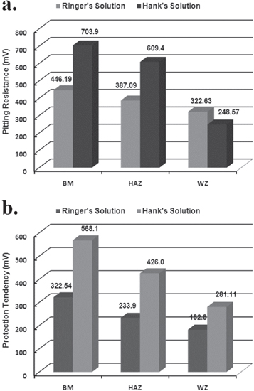
Figure 9. Electrochemical properties of weldments evaluated from the cyclic polarization trends (a) pitting protection (b) protection tendency; note: the values reported here are the average values with standard deviation of ±5%.
Download figure:
Standard image High-resolution imageThe higher pitting resistance of BM than HAZ and WZ demonstrated the direct relation with the microstructural inhomogeneity produced during weld thermal cycle. The decreasing trend in the pitting resistance from BM to WZ indicated the active localized dissolution of HAZ and WZ. The pitting resistance and protection tendency of welded samples in Ringer's solution was lower than in Hank's solution which could be associated with the high activity of Cl− ions species in the former electrolyte. Also, the  and
and  species present in the Hank's solution could preferentially adsorb at the active sites and may possibly restrict the dissolution tendency. The variation in the δ-ferrite concentration and other phases in the microstructure of HAZ and WZ could deteriorate the uniformity of passive film. It has been evaluated that the heterogeneity in the microstructure during welding could deleteriously affect the corrosion properties of AISI 316L and may accelerate localized dissolution of WZ in the simulated physiological solution.
4. Conclusion
- 1.This study concluded that welding thermal cycle greatly affected the microstructural, mechanical and electrochemical characteristics of the AISI316L weldment.
- 2.The formation of δ-ferrite and other phases in the WZ were confirmed from EDX and XRD analysis which possibly deteriorate the mechanical properties of the weldment by decreasing % elongation and fracturing through the WZ during tensile test experiments.
- 3.The fracture surface morphology also revealed mixed mode (Dimple + Cleavage) type of failure due to microstructural features of WZ.
- 4.The higher concentration of δ-ferrite and formation other phases in the WZ deleteriously affected the electrochemical properties of the weldment.
- 5.The relatively higher corrosion rate, lower pitting resistance and protection tendency of WZ than BM was confirmed from the potentiodynamic and CP analyses.
- 6.The Ringer's solution in contrast to Hank's solution was more aggressive towards BM, HAZ and WZ. The presence of
 and species in the Hank's solution may preferentially adsorb at the active sites and may possibly hinder the pitting corrosion of AISI 316L weldment.

