
Abstract
Gaining growing attention in spintronics is a class of magnets displaying zero net magnetization and spin-split electronic bands called altermagnets. Here, by combining density functional theory and symmetry analysis, we show that RuF4 monolayer is a two-dimensional (2D) d-wave altermagnet. Spin–orbit coupling leads to pronounced spin splitting of the electronic bands at the Γ point by  and turns the RuF4 into a weak ferromagnet due to nontrivial spin-momentum locking that cants the Ru magnetic moments. The net magnetic moment scales linearly with the spin–orbit coupling strength. Using group theory we derive an effective spin Hamiltonian capturing the spin-splitting and spin-momentum locking of the electronic bands. Disentanglement of the altermagnetic and spin–orbit coupling induced spin splitting uncovers to which extent the altermagnetic properties are affected by the spin–orbit coupling. Our results move the spotlight to the nontrivial spin-momentum locking and weak ferromagnetism in the 2D altermagnets relevant for novel venues in this emerging field of material science research.
Export citation and abstract BibTeX RIS

Original content from this work may be used under the terms of the Creative Commons Attribution 4.0 license. Any further distribution of this work must maintain attribution to the author(s) and the title of the work, journal citation and DOI.
1. Introduction
A recent discovery of non-relativistic spin splitting in electronic bands of materials with compensated collinear magnetic order opened a new venue in antiferromagnetic spintronics [1–3]. These intriguing materials constitute a separate magnetic phase, besides ferromagnets (FM) and antiferromagnets (AF), dubbed the name altermagnets (AM) [4, 5] or, alternatively, antiferromagnets with non-interconvertible spin-structure motif pair [6–9]. Altermagnets display a profusion of diverse physical phenomena, including anomalous Hall effect [10], piezoelectricity [11], and chiral magnons [12]; they can be used for efficient spin-charge interconversion [13], to generate orientation-dependent spin-pumping currents [14] and to proximitize superconductor materials [15–17], just to scratch the manifold of their possible applications.
Many altermagnetic compounds have been classified so far [18, 19], including MnTe [20, 21], MnF2 [22], RuO2 [4, 10, 23] and CrSb [24]. In MnTe the spin splitting of  is experimentally determined by angle-resolved photoemission spectroscopy (ARPES) measurements, thus confirming its altermagnetic status previously predicted by density functional theory (DFT) calculations. For possible spin-transport applications, apart from the magnitude of the splitting energy, the positioning of the spin-split bands is highly important. In this respect, CrSb may be a promising candidate for producing spin-polarized currents as a giant spin splitting of
  occurs just below the Fermi energy [24].
Regarding their dimensionality, all the previously mentioned altermagnets are three-dimensional (3D) compounds, and as of now, reports on two-dimensional (2D) altermagnets are limited. In the work of Brekke et al [25], it is proposed that magnon-mediated superconductivity in a 2D altermagnet could result in a superconductor with substantially enhanced critical temperature. However, this is accomplished using a microscopic model, and no specific material has been suggested to test this result. Very recently, monolayer Cr2Te2O is predicted as a promising platform for practical realization of the spin Seebeck and spin Nernst effects of magnons [26]. Further, it is shown that monolayer MnPS3, which is a conventional antiferromagnet, can be converted into altermagnet if one of its S layers is replaced by Se [27]. However, in thus obtained MnP(S,Se)3 Janus monolayer, the spin splitting of the relevant top valence band is modest, not exceeding  in the best case. Considering this, the endeavor to fabricate the Janus monolayer might be deemed excessively demanding in comparison to the anticipated benefits. Hence, for prospective applications in miniature and highly efficient spintronic devices, it would be beneficial to have 2D materials that inherently exhibit altermagnetic properties.
There is yet an important peculiarity concerning 2D magnets in general. Namely, in the absence of an external magnetic field the long-range order of spins on a 2D lattice can sustain above  temperature only if the system possesses the magnetic anisotropy energy (MAE) [28]. MAE is crucial here as it gaps the magnon spectra. Otherwise, the low-energy magnon excitations would destroy the long-range order at arbitrary non-zero temperatures. In this respect, altermagnets are not any different from ferromagnets and antiferromagnets. MAE, in turn, requires the presence of a sizable spin–orbit coupling (SOC) in the system. Therefore, for a realistic description of a 2D altermagnet the SOC must be accounted for. This raises a question—to what extent its non-relativistic properties, e.g. the hallmark spin splitting of bands, are affected by SOC?
Here, we show that in the non-relativistic limit monolayer RuF4 is a 2D altermagnet and we describe the spin splitting of band structure and spin textures of the altermagnetic phase. Subsequently, we analyze the influence of SOC on the altermagnetic properties. The structure of monolayer RuF4, and its crystallographic and magnetic symmetries, are described in section 2.1. The altermagnetic phase is analyzed in section 2.2. Weak ferromagnetism and SOC-induced spin splitting of bands are exposed in sections 2.3 and 2.4. Finally, we summarize the paper in section 3 with an outlook on the link between altermagnetism and weak ferromagnetism.
2. Results
2.1. The structure and crystal symmetries of RuF4 monolayer
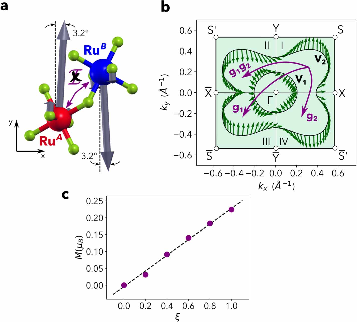
Monolayer RuF4 is composed of ruthenium atoms sitting in the centers of fluorine octahedra. It is a van der Waals material that can be exfoliated from the bulk compound which was experimentally synthesized in monoclinic  crystallographic space group (group No. 14) [29]. We will refer to a Ru atom with its surrounding F ligands as the Ru cluster. In each Ru cluster, two out of six F atoms belong only to that cluster, whereas four of them are shared by the four nearest neighbors. The crystal lattice of monolayer RuF4 has two sublattices with symmetrically distinct Ru clusters, RuA
and RuB
, that are arranged as depicted in figure 1.
crystallographic space group (group No. 14) [29]. We will refer to a Ru atom with its surrounding F ligands as the Ru cluster. In each Ru cluster, two out of six F atoms belong only to that cluster, whereas four of them are shared by the four nearest neighbors. The crystal lattice of monolayer RuF4 has two sublattices with symmetrically distinct Ru clusters, RuA
and RuB
, that are arranged as depicted in figure 1.
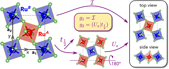
Figure 1. Structure of monolayer RuF4 and a schematic depiction of transformations  and
and  that are generators of its crystallographic group. Distinct Ru clusters are depicted by red (RuA
) and blue (RuB
) octahedra.
that are generators of its crystallographic group. Distinct Ru clusters are depicted by red (RuA
) and blue (RuB
) octahedra.
Download figure:
Standard image High-resolution imageTwo perpendicular lattice vectors that define the RuF4 plane, a1 and a2, have different lengths,  Å and
Å and  Å, as obtained from our DFT calculations. Therefore, we will refer to the two directions defined by these vectors as the shorter and the longer in-plane directions. The structure of monolayer RuF4 belongs to the
  layer group (layer group No. 17) [30] which has two generators: the space inversion
  and the non-symmorphic group element
  that is the combination of two operations each transforming RuA
into RuB
and vice versa: a rotation Ux
by 180∘ around the shorter in-plane direction a1 and a fractional lattice translation
that is the combination of two operations each transforming RuA
into RuB
and vice versa: a rotation Ux
by 180∘ around the shorter in-plane direction a1 and a fractional lattice translation  . Therefore, the group symmetry consists of four elements,
  , where e is the identity element and
  represents a joint action of the group generators. Importantly, the crystal structure is centrosymmetric, but the Ru–Ru bond does not have the point of inversion, meaning that the Dzyaloshinskii–Moriya interaction can occur between the Ru magnetic moments [31]. We will discuss this in detail in the remainder of the manuscript.
2.2. Non-relativistic description of magnetic properties: 2D altermagnet
RuF4 has a compensated net magnetic moment due to the opposite magnetic moments on the two Ru sublattices. Octahedral crystal field of F− ions acts on Ru4+ ion, leading to the  splitting of its 4d orbitals and leaving two spin-unpaired electrons in the
  manifold. Therefore, from the crystal field theory, magnetic moments of
  are expected on Ru atoms. Our DFT calculations give
  , in agreement with the value reported in [32]. The discrepancy between the expected and the DFT-calculated magnetic moments is due to the hybridization between the Ru 4d and the F 2p orbitals. Concretely, the F atoms that belong to a single Ru cluster exhibit moderate magnetic moments of 0.214 µB, induced by the nearest Ru magnetic moment, that are coupled ferromagnetically to that moment. On the other hand, the F atoms shared between two clusters are bonded to the two opposite-spin Ru atoms and are thus non-magnetic. In summary, the magnitude of the magnetic moment on each Ru cluster is
  .
.
In the absence of an external magnetic field and without SOC, the direction of magnetic moments and thus the Néel vector (N) is arbitrary. To perform symmetry analysis, we assume that N points along the longer in-plane lattice direction a2, which coincides with the y-axis in our choice of coordinate frame (see figure 1). Space inversion g1 has a trivial effect on magnetic moments as they are pseudovectors, whereas g2 leaves the magnetic order invariant because the rotation Ux
and the fractional lattice translation  each reverse the magnetic order. Therefore, all the symmetry operations from the
  layer group leave the magnetic order unaltered and are thus the symmetries of the magnetic system as well, meaning that the magnetic space group is equal to its parent crystallographic group (type-I). Given that (1) the magnetic space group is of type-I [33] and (2) the combination
  of time reversal θ and space inversion symmetry
  is broken due to the magnetic order, the non-relativistic spin splitting in monolayer RuF4 is allowed [8, 18].
In figure 2(a) we plot the band structure of monolayer RuF4 calculated with spin-polarized DFT calculations. The system is a semiconductor with an indirect band gap of  between the valence band maximum, located on the XY path, and the conduction band minimum located at S.

Figure 2. Non-relativistic RuF4 band structure calculated with spin-polarized DFT calculations. In (a), the  path is assumed and the spin splitting energies of the top valence (V
 ) and bottom conduction (C
 ) bands are given in the inset (yellow rectangle). In (b) the top valence band V
 is illustrated once again along the
  path, and the d-wave nature of its spin-momentum locking in the full Brillouin zone (green rectangle) at
  below the Fermi energy is illustrated in (c).
Download figure:
Standard image High-resolution imageAlong the chosen k-path in the Brillouin zone (BZ), the spin-up and spin-down bands are degenerate along the ΓX, XS, and ΓY lines, whereas a sizable spin splitting  (n is the band index) is observable along the ΓS and XY lines. Notably, of all the bands in the energy window from
  below to
  above
above  , the spin splitting is the largest for the top valence (V
 shown in figure 2(b)) and the bottom conduction bands (C
 ), reaching
  and
and  , respectively (yellow rectangle in figure 2(a)). The spin-momentum locking of the bands V
 presented in figure 2(c) clearly shows that monolayer RuF4 is a d-wave altermagnet [4].
To model the spin splitting of these bands around the Γ point we employ a simple time-reversal breaking Hamiltonian, compatible with the system's symmetry,
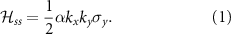
Here  and α is the band-dependent parameter determined by fitting the model to the DFT bands. For the V
 and C
and C , up to the 25% of the ΓX line, the spin splitting in an arbitrary k-direction can be described using
  meV Å2 and
  meV Å2.
As DFT calculations pointed out, the spin degeneracy of bands is not lifted along the ΓX and ΓY lines. This can be explained by analyzing how the group elements connect different points of the energy surface  . Keeping the assumption that magnetic moments are in the y-direction, the action of group elements reflects on the electronic bands as
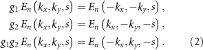
Based on the equations (2), one concludes that along ΓX, where  , and ΓY, where
  , the relations
express the spin degeneracy. On the other hand, these constraints are not present along an arbitrary k path and the spin splitting of bands is not forbidden. This is exactly the case of the ΓS and XY lines, where we observe a noticeable non-relativistic spin splitting, which is the hallmark of the altermagnetic phase.
2.3. SOC turning altermagnet into a weak ferromagnet
To investigate SOC effects on the magnetic ordering in RuF4, we add to the one-electron DFT Hamiltonian a symmetry-independent relativistic correction. For more details see section 4. As SOC entangles spin space and real space, the Néel vector N obtains a defined crystallographic direction. Our DFT calculations reveal that the shorter in-plane lattice direction (the y-axis) is the preferential direction for N, with MAE separating it from the longer in-plane direction (x-axis) and from the out-of-plane direction (z-axis) by  and
and  , respectively.
Due to SOC, the magnetic moments are getting canted from the y-axis towards the x-axis by 3.2∘, as depicted in figure 3(a). Canting lowers the total energy only slightly ( ), but it induces a net magnetic moment of
  which points in the +x direction. Therefore, upon the inclusion of SOC, the monolayer RuF4 changes its magnetic phase from the altermagnetic to the weak ferromagnetic [34] (WF) phase.

Figure 3. (a) SOC-induced canting of magnetic moments on two sublattices of RuF4. (b) Spin textures of the top valence bands V1 and V2 at energy −0.15 eV below the Fermi level. (c) Dependence of induced net magnetic moment on the SOC strength.
Download figure:
Standard image High-resolution imageThe direction of the induced magnetic moment in RuF4 can be inferred from the group theory analysis. In general, the magnetic moment 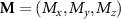 of any system must stay invariant under the action of all the group symmetry elements. Since the inversion g1 has a trivial action on the pseudovector M through the
  representation [35],
  , whereas the group elements g2 and
  change the sign of the y and z component of M,
 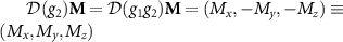 , both the My
and Mz
must be zero. Therefore, the net magnetic moment of RuF4 must point along the x-axis, in accordance with our DFT results.
, both the My
and Mz
must be zero. Therefore, the net magnetic moment of RuF4 must point along the x-axis, in accordance with our DFT results.
The transition from the altermagnetic to the weak ferromagnetic phase leaves its fingerprints on the spin texture. The spin texture is a vector field in the reciprocal space defined through the expectation value of the spin operator  in a given Bloch state
  ,
,

The spin texture, like the net magnetic moment, complies with the symmetry of the system. We provide detailed derivation in appendix
where  is the Kronecker delta, equal to 1 if i = x and 0 otherwise.
The equation (5) shows that the spin texture in the I quadrant of the BZ  is related to the spin texture in the II, III, and IV through the action of the group elements
  , g1, and g2, respectively. We can illustrate these relations on a concrete example. In figure 3(b) we show the spin texture of the valence bands V
 at the constant energy surface
  below the Fermi level. Now, it is clear that the spin expectation values
  from the II and IV quadrants cancel out the spin expectation values in the I and III quadrants (actually
  is zero everywhere, which is not shown in the plot). The cancellation of the spin expectation values from different quadrants of the BZ leads to the vanishing of My
and Mz
in the real space. Indeed, each component of the net magnetic moment can be expressed as an integral of the corresponding spin expectation values over the BZ,
is zero everywhere, which is not shown in the plot). The cancellation of the spin expectation values from different quadrants of the BZ leads to the vanishing of My
and Mz
in the real space. Indeed, each component of the net magnetic moment can be expressed as an integral of the corresponding spin expectation values over the BZ, 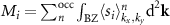 , where the 'occ' denotes that the sum runs over the occupied states. On the other hand,
  in all the four quadrants, yielding non-zero Mx
.
in all the four quadrants, yielding non-zero Mx
.
In the following, we question the microscopic mechanism responsible for canting the magnetic moments. In the work of Wang et al [32] it is shown that the Dzyaloshinskii–Moriya interaction (DMI) acting between the Ru moments is mainly responsible for their canting, with some contribution from the single-ion anisotropy (SIA). The DMI between the opposite-spin Ru atoms is allowed because the Ru–Ru bond does not display inversion [31], as we mentioned in section 2.1. Given that SOC is the common origin of both the DMI and SIA, the magnitude of the induced net magnetic moment must depend on the SOC strength. To shed light on this relation, we scale the SOC strength in DFT calculations by using the modified SOC constant  , where the dimensionless parameter ξ ranges from 0 (no SOC) to 1 (realistic SOC). Then, we constrain the magnetic moments in the directions that are canted by angle α from the y-axis. For a set of directions α the equilibrium canting angle αξ
is found by minimizing the auxiliary function
, where the dimensionless parameter ξ ranges from 0 (no SOC) to 1 (realistic SOC). Then, we constrain the magnetic moments in the directions that are canted by angle α from the y-axis. For a set of directions α the equilibrium canting angle αξ
is found by minimizing the auxiliary function 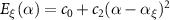 , where
  is the total energy of the system for a particular canting angle α and SOC strength
  . Finally, for each ξ we perform DFT calculations for magnetic moments canted by αξ
and we calculate the net magnetic moment. The plot in figure 3(c) shows that the net magnetic moment is linear in SOC strength.
. Finally, for each ξ we perform DFT calculations for magnetic moments canted by αξ
and we calculate the net magnetic moment. The plot in figure 3(c) shows that the net magnetic moment is linear in SOC strength.
The linearity of the dependence  can be explained by turning to the microscopic expression for the DMI. First, we noticed that the magnitude of the Ru cluster's magnetic moment
 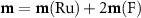 is almost unaffected by SOC, changing only slightly from
  for ξ = 0 to
  for ξ = 1 while
  does not change at all, staying
  . Second, the magnitude
  of the net magnetic moment
  and the canting angle αξ
are related by
and the canting angle αξ
are related by  , where
  . Now, assuming that canted magnetic moments stay in the xy-plane, the DMI energy can be expressed as

where  . As pointed out by Moriya [31], the magnitude of the Dzyaloshinskii vector is linear in SOC constant,
  (here
(here  as we are using the scaled SOC constant), whereas its direction depends on the symmetry of the structure. Therefore, the angle
  does not depend on
  and the DMI energy can be expressed as
 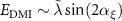 . As long as the canting angle is small the approximate relation
  holds. Noticing that the DMI energy is quadratic in Dzyaloshinskii vector magnitude [36],
  , the last relation shows that the canting angle is linear in the modified SOC constant,
  . Finally, for small canting angles, the linearity of the
  dependence stems from the relation
 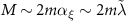 .
.
2.4. SOC-induced spin splitting of bands
Spin–orbit coupling, besides inducing net magnetic moment in the 2D altermagnet RuF4, is responsible for significant (additional) spin splitting of the electronic bands. To shed light on this SOC effect, in figures 4(a) and (b) we plot the band structure calculated with SOC along the same k-path and in the same energy window as in the figure 2. In addition, we project the spin expectation values  and
and  over each band to reveal how their spin polarization evolves along different k-directions.

Figure 4. Non-collinear relativistic DFT calculations of the band structure for RuF4 along high symmetry lines. (a) spin expectation values  and (b)
  plotted as a band color. (c) spin splitting of the top valence V
 and bottom conduction bands C
 is along the same k-path given, with the AM-induced spin splitting plotted for comparison with dashed lines. (d) spin splitting of V
 and C
and C at the Γ point calculated for the different SOC strength ξ. (e) the difference between spin splitting energies with and without SOC of V
 and C
and C bands along the ΓS path for different SOC strengths ξ.
Download figure:
Standard image High-resolution image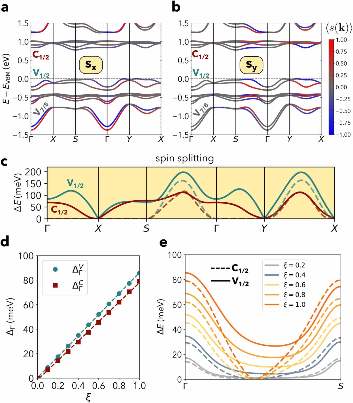
Due to SOC, the bands V and C
and C , which are degenerate in the AM phase along some special k-directions, are now split in almost the entire BZ, displaying highly nonuniform splitting energies (figure 4(c)). Intriguingly, the non-relativistic (AM-induced) and relativistic (SOC-induced) spin splitting reach their respective maxima in different regions of the BZ: while SOC-induced splitting is maximal at Γ and S points, where the bands were previously degenerate in the AM phase, the AM-induced splitting in the middle of the ΓS and XY lines is barely affected by SOC.
Apart from the splitting energies, the polarization of bands displays non-uniform k-dependence. For example, the V bands are polarized in the x-direction along the ΓX and ΓY lines, with
  for V1 and
  for V2 (figures 4(a) and (b)). The polarization in the x-direction along these k-lines is the most evident for the V
 bands. On the other hand, both
  and
and  are nonzero and vary substantially along the ΓS and XY lines, meaning that V
 have mixed polarization along these directions. Also, there are k-directions along which the bands are almost unpolarized, such as the XS line where
  .
.
The point that deserves special attention is the lifting of spin degeneracy along the  path. What is particularly striking is a large spin splitting at Γ, which is a time-reversal invariant momenta (TRIM) point, of
 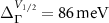 and
and  for the V
 and C
and C bands, respectively. Moreover,
  scales linearly with the SOC strength, as shown in figure 4(d). At first glance, this linear splitting seems to occur due to a nonzero net magnetic moment pointing in the x-direction, but our additional DFT calculations reveal that even when the Ru magnetic moments are strictly constrained in the y-direction (so that
  ), the spin splitting of bands along
  persists.
To shed light on this, let us consider a non-relativistic Hamiltonian of the AM phase  and include SOC as a perturbation. The complete derivation is exposed in appendix
  point,
 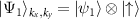 and
and 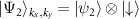 , are with the same energy E, the perturbation
  in the
 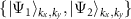 basis has the matrix elements of the form
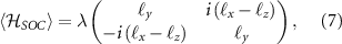
where  ,
,  , are real numbers related to nonzero matrix elements of the pseudovector operator L, see appendix
 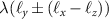 , meaning that SOC lifts the degeneracy of
  and
and  inducing the spin splitting of
 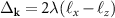 . The derivation exposed in appendix
The spin degeneracy along the ΓS and XY lines is lifted already in the AM phase, but the inclusion of SOC changes this spin splitting drastically. To show how the SOC-induced splitting gradually develops over the AM-induced one, we plot the difference of the SOC-induced and AM-induced splitting energies for V and C
and C bands along the ΓS path for different SOC strengths
  (figure 4(e)). As ξ varies from 0 to 1 the SOC-induced splitting increases, but the fraction of the ΓS path where it dominates over the AM-induced splitting never surpasses 40%. Therefore, the AM-induced splitting is still dominant along the ΓS line despite the sizable SOC-induced spin splitting.
3. Discussion and conclusion
In this work, we have shown that in the non-relativistic limit, the monolayer RuF4 represents a 2D d-wave altermagnet. Using the type-I magnetic space group, we have revealed the symmetry properties of the non-relativistic spin splitting in the altermagnetic phase. By applying the theory of invariants, we have derived a simple model Hamiltonian that captures the spin-momentum locking of the top valence and the bottom conduction bands, both of which can be activated for spin transport by carrier doping. In the relativistic limit, we have shown that spin–orbit coupling induces weak ferromagnetism and significantly changes the spin splitting and the spin texture of bands. Using the perturbation theory, we explained the appearance of a sizable SOC-induced spin splitting at the time-reversal invariant Γ point, which is reminiscent of Zeeman splitting but occurs even in the limit of vanishing net magnetic moment. We have shown that the magnetic moment induced due to canting of Ru spins is linear in SOC strength. This implies that in altermagnetic compounds containing heavy atoms, which exhibit very strong SOC, the altermagnetic phase could be significantly altered. The presence of the weak ferromagnetism in our system, originating from the SOC, could be detected using the charge-spin interconversion schemes [37, 38]. By applying a current in the y-direction, the nonzero spin accumulation due to the Rashba–Edelstein effect [39] would be a signature of the canted magnetic moments of Ru. Alternatively, weak ferromagnetism can be measured using standard magnetometry techniques or neutron diffraction [40].
Finally, it is worth noting that Autieri et al [41] recently highlighted that the emergence of weak ferromagnetism in metallic altermagnets is a property unparalleled in conventional antiferromagnets. As such, the appearance of weak magnetization in metallic compounds can be used to demarcate the conventional antiferromagnets from altermagnets. Yet, as we have shown in this work, RuF4 is a semiconductor and we argue that the appearance of SOC-induced weak ferromagnetism may be a general property of all the altermagnetic compounds, not just metallic ones. Actually, this opens additional possibilities once one realizes that the small component of net magnetic moment, induced by SOC, could be employed as a knob to control the direction of dominant magnetic arrangement in altermagnets. Indeed, the Néel vector in weak ferromagnets can be dragged by a small external magnetic field using the experimental technique exposed in the work of Dmitrienko et al [42]. In this way, one could control the direction of spin-polarized currents in altermagnets. Therefore, we strongly believe that the relation between weak ferromagnetism and altermagnetism warrants greater attention, and would stimulate interest to delve into this intriguing topic.
4. Methods
DFT calculations were performed using the VASP code [43]. The effects of electronic exchange and correlation were described at the Generalized Gradient Approximation (GGA) level using the Perdew–Burke–Ernzerhof (PBE) functional [44]. The Kohn–Sham wavefunctions were expanded on a plane wave basis set with a cutoff of  . We used the projector-augmented wave (PAW)[45] pseudopotentials with Ru 4p,5s,4d and F 2s,2p states as valence states. The lattice constants
  Å and
Å and  Å were obtained from spin-polarized non-relativistic DFT calculations using the Birch–Murnaghan equation of state and assuming the antiparallel arrangement of RuA
and RuB
magnetic moments. In the out-of-plane direction, we used the lattice constant of a3 = 20 Å to ensure sufficient separation between the periodic replicas. The atomic positions were relaxed until all the forces' components dropped below 0.002 eV/Å−2. The Brillouin zone was sampled with
Å were obtained from spin-polarized non-relativistic DFT calculations using the Birch–Murnaghan equation of state and assuming the antiparallel arrangement of RuA
and RuB
magnetic moments. In the out-of-plane direction, we used the lattice constant of a3 = 20 Å to ensure sufficient separation between the periodic replicas. The atomic positions were relaxed until all the forces' components dropped below 0.002 eV/Å−2. The Brillouin zone was sampled with  k points mesh during the relaxation and with a finer
  mesh during the self-consistent field calculations. To find the canting angle of the Ru magnetic moment we performed magnetic non-collinear DFT calculations with SOC and for a set of directions we constrained the magnetic moments using the penalty functional [46]. The SOC in the VASP code is implemented by adding a term
 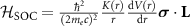 to the one-electron DFT Hamiltonian, where L is the angular momentum operator,
  is the vector of Pauli spin matrices, V(r) is the spherical part of the effective all-electron potential inside the PAW sphere, and
  , as explained in [47]. As the SOC is a relativistic interaction, it is assumed that the predominant contribution comes from the regions close to the nuclei. Therefore, the matrix elements of the
  operator are neglected outside the PAW spheres. For plotting bandstructure and spin texture we used the Pyprocar package [48]. For setting up DFT calculations and for structural visualization we used the Atomic Simulation Environment [49], XCrySden [50], and Vesta [51] packages.
Acknowledgments
We acknowledge support from the Italian Ministry for Research and Education through the Nanoscience Foundries and Fine Analysis (NFFA-Trieste, Italy) project and through the Next-Generation EU program PRIN-2022 project "SORBET: Spin-ORBit Effects in Two-dimensional magnets" (IT MIUR Grant No. 2022ZY8HJY). M M, M O, and S S acknowledge the financial support provided by the Ministry of Education, Science, and Technological Development of the Republic of Serbia. This project has received funding from the European Union's Horizon 2020 Research and Innovation Programme under the Programme SASPRO 2 COFUND Marie Sklodowska-Curie Grant Agreement No. 945478. M G acknowledges financial support provided by the Slovak Research and Development Agency under Contract No. SK-SRB-23-0033 and by the Ministry of Education, Science, Research and Sport of the Slovak Republic provided under Grant No. VEGA 1/0695/23 and Slovak Academy of Sciences project IMPULZ IM-2021-42 and project FLAG ERA JTC 2021 2DSOTECH. The authors gratefully acknowledge the Gauss Centre for Supercomputing e.V. for providing computational resources on the GCS Supercomputer SuperMUC-NG at Leibniz Supercomputing Centre. We acknowledge the CINECA award under the ISCRA initiative, for the availability of high-performance computing resources and support.
Data availability statement
All data that support the findings of this study are included within the article (and any supplementary files).
Conflict of interest
The authors declare no competing financial or non-financial interests.
Author contributions
S S and M M conceived the project. S S and M O performed the first-principles simulations and M M performed the symmetry analysis and perturbation theory analysis, supported by M G. All the authors discussed the results and contributed to the writing of the manuscript.
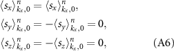
Appendix A: General constraints on spin expectation values in the relativistic case
Let  represent an eigenstate of the altermagnetic Hamiltonian in a relativistic phase

with group symmetry  of both the relativistic and/or altermagnetic phase, since the magnetic space group is equal to the crystallographic group, see section 2.2. The commutation relation
 ![$[d(g),\mathcal{H}_{\mathrm{AM}}^\textrm{rel}] = 0$](https://content.cld.iop.org/journals/2053-1583/11/3/035025/revision2/tdmad4c73ieqn150.gif) holds for any element
holds for any element  , where d is the representation of the group acting in the Hilbert space of the Hamiltonian
  . For a given state
  , the spin expectation values are defined as

Using the action of the group element  in the Hilbert space in which the Hamiltonian
  acts, the previous equation can be transformed to
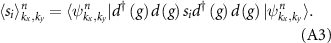
By analyzing the action of nontrivial group elements  ,
,  and
and  , one obtains general constraints on the spin expectation values
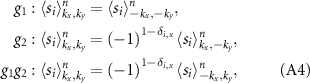
where  is the Kronecker delta, equal to 1 if i = x and 0 otherwise. To obtain the previous relations, we have used the following identities
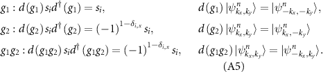
In short, the set of equations (A4) show that in a system with  symmetry the spin texture
  can accumulate, yielding a finite net magnetic moment in the x-direction, whereas the
  and
and  from different quadrants of the BZ cancel out, as explained in the main text and illustrated in figure 3(b).
Furthermore, the equations (A4) in the special cases of the Γ point and along the ΓX and ΓY lines, suggest that spin expectation values are nonzero in the x-direction solely since for  (ΓX line) we have
while along the ΓY line ( ) one gets

This conclusion is in agreement with the band structure plotted in figure 4 which shows that along the  path the x-component of spin is nonzero (blue and red bands figure 4(a)) while the y-component equals to zero (gray bands figure 4(b)).
Also, it should be mentioned that the conclusions agree with the ones given in appendix B, where we have shown that the SOC is solely responsible for the observed splitting along the high-symmetry lines ΓX and ΓY, as well as in the Γ point.
Appendix B: Perturbation theory of SOC-induced removal of spin degeneracy at arbitrary k point
The spin splitting at the Γ point and along the ΓX and ΓY lines can be explained using the perturbation theory, where the SOC Hamiltonian is introduced as a perturbation. To do this, we apply a first-order degenerate perturbation theory, valid for bands not only along the  path but also at other k points of the Brillouin zone that host the degenerate bands in the altermagnetic phase.
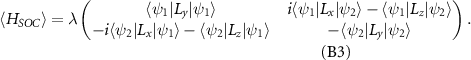
We describe the two degenerate states as 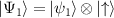 and
and 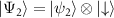 , where
  corresponds to the orbital part of the wave function, while
  are eigenstates of the Pauli σy
operator for the eigenvalues 1 and −1, respectively. We chose σy
because we assumed that the spin quantization axis is along the y-direction. Now, if the
are eigenstates of the Pauli σy
operator for the eigenvalues 1 and −1, respectively. We chose σy
because we assumed that the spin quantization axis is along the y-direction. Now, if the  is the non-relativistic one-electron Hamiltonian (AM emphasizes here that this is the non-relativistic Hamiltonian of the altermagnetic phase), then the following relation holds

In the orbital space the action of the group element g2 is through the representation  , while in the magnetic space acts as a representation dM
,
, while in the magnetic space acts as a representation dM
,  , which flips the magnetic moments
 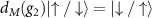 . Using the commutation relation between the Hamiltonian and the elements of the group,
 ![$[d_O(g_2)\otimes d_M(g_2),\mathcal{H}^\textrm{nrel}_\textrm{AM}] = 0$](https://content.cld.iop.org/journals/2053-1583/11/3/035025/revision2/tdmad4c73ieqn176.gif) , one can say that
, one can say that
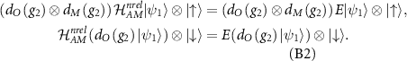
The last relation is equal to  , which leads us to conclude that the relation
  must hold. Furthermore, noticing that
  , where I is the identity matrix, one concludes that
  , which suggests that the relation
  holds. Therefore, the group element g2 interchanges the orbital parts of two degenerate states. This will be useful for calculating the matrix elements of the SOC operator in the
  basis.
To account for the SOC effects we use the first-order perturbation theory and calculate the allowed matrix elements of the operator 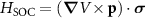 , where
  represents the gradient of the crystal potential, p the momentum operator, and
σ
the Pauli operator. Now, the fact that
represents the gradient of the crystal potential, p the momentum operator, and
σ
the Pauli operator. Now, the fact that  transforms as a pseudovector allows us to rewrite the SOC Hamiltonian as
  , where λ describes the SOC strength. Note that L
is not the angular momentum but it transforms like one. Now, the matrix elements of
, where λ describes the SOC strength. Note that L
is not the angular momentum but it transforms like one. Now, the matrix elements of  in the
  basis are
Here we have used that the Pauli operators in a given spin basis 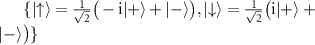 (
( are eigenvectors of the σz
operator,
are eigenvectors of the σz
operator,  ) are equal to
  ,
,  ,
,  . The symmetry argument in this case gives us
where we have used that  and that
  is the real number. Also, we calculate the matrix elements
  and
and  ,
,
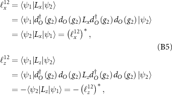
and use the relations  and
and  .
.
The conditions obtained in (B5) imply that  and
and  , where
  , allowing us to simplify
  to
to
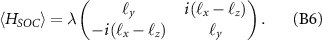
Using the final form of  given by equation (B6), the SOC-induced energy contribution to the degenerate level in the altermagnetic case is equal
 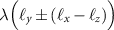 . The spin splitting due to the SOC is equal to
  . Furthermore, by calculating the eigenvectors of
  , where E0 represents the energy of the double degenerate bands, while I2 is the
  identity matrix in the eigenbasis
  of the altermagnetic phase, we find that the spin expectation values have the nonzero component in the x-direction only, consistent with the general conclusion from appendix A. However, the first-order perturbation theory predicts
  (in the units of
  /2) at the Γ point, which is not consistent with the data obtained from first-principles calculations, where
  . This implies that the higher-order perturbation theory needs to be applied to account for the interaction with the bands higher in energy, responsible for the reduction of the intensity of the spin expectation value.