

Abstract
Pre-vascularization has been receiving significant attention for developing implantable engineered 3D tissues. While various pre-vascularization techniques have been developed to improve graft vascularization, the effect of pre-vascularized patterns on in vivo neo-vessel formation has not been studied. In this study, we developed a functional pre-vascularized construct that significantly promotes graft vascularization and conducted in vivo evaluations of the micro-vascular patterns (μVPs) in various printed designs. μVP formation, composed of high-density capillaries, was induced by the co-printing of endothelial cells and adipose-derived stem cells (ADSC). We implanted the printed constructs with various μVP designs into a murine femoral arteriovenous bundle model and evaluated graft vascularization via 3D visualization and immune-histological analysis of the neo-vessels. The μVP-distal group (μVP located away from the host vessel) showed approximately two-fold improved neo-vascularization compared to the μVP-proximal group (μVP located near the host vessel). Additionally, we confirmed that the μVP-distal group can generate the angiogenic factor gradient spatial environment for graft vascularization via computational simulations. Based on these results, the ADSC mono pattern (AMP), which secretes four times higher angiogenic factors than μVP, was added to the μVP + AMP group design. The μVP + AMP group showed approximately 1.5- and 1.9-fold higher total sprouted neo-vessel volume than the μVP only and AMP only groups, respectively. In immunohistochemical staining analysis, the μVP + AMP group showed two-fold improved density and diameter of the matured neo-vessels. To summarize, these findings demonstrate graft vascularization accelerated due to design optimization of our pre-vascularized constructs. We believe that the developed pre-vascularization printing technique will facilitate new possibilities for the upscaling of implantable engineered tissues/organs.
Export citation and abstract BibTeX RIS
1. Introduction
Engineering artificial tissues is an essential aspect of regenerative medicine aimed to replace and restore the functionality of damaged organs [1]. Hence, many advanced technologies have been developed to fabricate engineered tissues with architectures and functions similar to living tissues [2]. Recent fabrication techniques for hierarchical and branched vascular networks are particularly notable for the developing volumetric tissue constructs [3]. Several studies have reported the engineering of functional in vitro cardiac and hepatic models with perfusable 3D vascular structures [4–6]. Further, the transplantation of engineered tissues with direct anastomosis between pre-vascularized structures and host vessels has been attempted recently to address the hypoxic environment within the graft [6–9]. Szklanny et al [9] demonstrated direct blood perfusion through implanted constructs maintained for 14 d via surgical anastomosis of a rat femoral artery and engineered macro-scale vessel. However, thrombosis, which frequently occurs due to the excessive reaction of platelets by the vasculature composed of foreign substances in contact with the blood, is a major limitation for the long-term blood supply to the implanted grafts [10].
Alternatively, the implantation of a pre-vascularized graft containing micro-scale capillaries has been widely studied to enhance in vivo graft vascularization [11–17]. Baranski et al [13] reported that hydrogel implantation of micro-vasculature in parallel-aligned patterns induced numerous host vessel formation along the pre-patterned regions. Additionally, Kang et al [14] demonstrated that grafts with aligned pre-vascularized structures induced faster in vivo neo-vascularization than those with randomized patterns. Similarly, several recent studies have reported that scaffolds with organized microvascular patterns (µVPs) promote the engraftment of pancreatic islets and hepatocytes [18, 19]. Essentially, engineered organized pre-vasculature has been shown to promote graft vascularization. However, only the in vivo functionality of simple aligned pre-vascularized patterns was confirmed by comparing randomized patterns. Additionally, the impact of the design of pre-vascularized patterns on in vivo graft vascularization remains unknown.
In this study, the effect of various pre-vascularized patterns on neo-vascularization was analyzed. Based on these results, our proposed pre-vascularization strategy to dramatically improve graft vascularization was established (figure 1(a)). We printed various designs of pre-vascularized constructs including the μVPs and adipose-derived stem cells (ADSC) mono pattern (AMP). Further, to confirm the in vivo functionality of the printed construct, we conducted animal experiments using a murine femoral arteriovenous (AV) bundle model. To precisely analyze the effect of graft vascularization, volumetric quantification of the sprouted neo-vessel was performed via tissue clearing and 3D imaging. Lastly, we confirmed the effectiveness of our in vivo graft vascularization strategy through experimental analysis and comparison with other pre-vascularized construct designs.
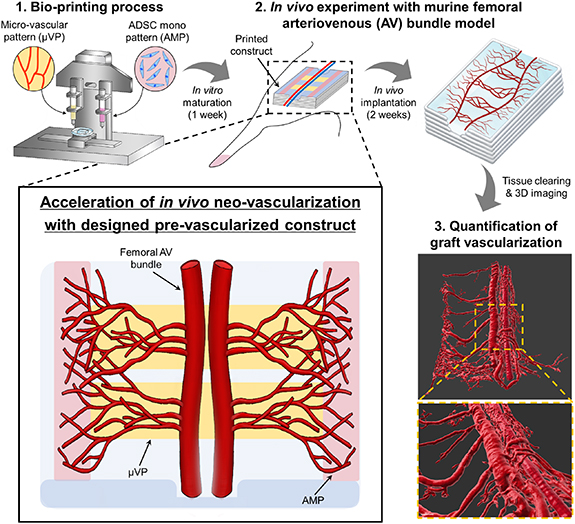
Figure 1. Designed pre-vascularized construct for enhanced in vivo neo-vascularization. Bioprinting of the designed pre-vascularized construct and experimental procedure for investigating graft vascularization within the printed constructs are illustrated.
Download figure:
Standard image High-resolution image2. Materials and methods
2.1. Cell culture
Green fluorescent protein expressing human umbilical vein endothelial cells (GFP-HUVEC; Angio-Proteomie, Boston, MA, USA) and HUVEC (Lonza, Basel, Switzerland) were cultured in Endothelial cell Growth Medium-2 Bulletkit (EGM-2; Lonza, Basel, Switzerland). Except for the cell viability test, all experiments were conducted with GFP-HUVEC. Human ADSC (Lonza) were cultured in Dulbecco's Modified Eagle Medium with low glucose (DMEM; Gibco, Marcq-en-Baroeul, France) containing 10% (v/v) fetal bovine serum (Gibco) and 1% (v/v) penicillin-streptomycin (Gibco). The cells were cultured in a humidified incubator at 37 °C and 5% CO2, and the culture media were replaced every 2–3 d. The subculture of cells was performed at 70%–80% confluency by treating with 0.05% trypsin/ethylene-diaminetetraacetic acid solution (Thermo Fisher Scientific Inc., Waltham, MA, USA). All the cells up to passage 7 were utilized in the experiments.
2.2. Preparation of cell-laden bio-inks
Two bio-inks were used for printing μVP and AMP. The bio-ink is a composite hydrogel comprising of hyaluronic acid (HA; Sigma, MO, St. Louis, USA, 3747), gelatin (Sigma, G6144), and fibrinogen (Sigma, F8630). The concentration of each component of the two bioinks was determined based on our previous study [20], and the printing performance of each bio-ink was tested prior to this study (figure S1). The bio-ink was fabricated by dissolving HA (3 mg ml−1) in a minimum essential medium (MEM; Corning, NY, USA) at 37 °C overnight with gentle rotation. Next, gelatin (40 mg ml−1) was added and incubated for 1 h at 37 °C. Subsequently, fibrinogen (5 mg ml−1 for μVP; 10 mg ml−1 for AMP) was dissolved in the mixture and further incubated for 30 min at 37 °C. All the bio-inks were sterilized using a 0.45 μm syringe filter and stored at −80 °C. Prior to bio-printing, the prepared bio-inks were melted in a water bath at 37 °C, and the cells were homogeneously mixed based on the following concentrations of each bio-ink; endothelial cells (EC; 5 × 10⁶ cells ml−1) and ADSC (1 × 10⁷ cells ml−1) for μVP and ADSC (2 × 10⁷ cells ml−1) for AMP.
2.3. Bio-printing process
All the printing procedures to fabricate the pre-vascularized grafts were performed using our custom-designed bioprinting system [20]. The bio-printing system consists of a motorized three-axis stage, multi-cartridge dispensing modules, and a closed chamber with a high efficiency particulate air (HEPA) filter and temperature/humidity controller.
To fabricate the grafts for transplantation into our animal model, we designed our constructs based on the desired μVP and AMP patterns. All constructs were prepared via layer-by-layer printing and molding of the surrounding matrix (figure S2). The construct size (6 × 6 × 0.75 mm3) was adjusted during the transplantation pilot study. For the in vitro study (viability assay and parameter study of EC/ADSC ratio), similar sized (7.5 × 6 × 0.75 mm3) printed constructs were utilized. The prepared bio-inks and polycaprolactone (PCL; Polysciences, Inc., PA, USA, molecular weight: 43 000–50 000) were sequentially printed. One milliliter sterilized plastic syringes containing the bio-inks were equipped with a 250 μm metal nozzle, and the bio-inks were extruded at 0.21 μl s−1 using mechanical dispensers. The printing speed and extruding time were controlled according to the desired pattern. PCL was dispensed via a 30 ml metal syringe through a 200 μm metal nozzle heated to 90 °C–95 °C under 210 kPa air pressure. To fabricate the frame of the construct, the PCL pattern was stacked with a printing speed of 200 mm min−1. All printing was performed at 18 °C maintained by the chamber system. After printing, the constructs were covered with a fibrin molding gel (1:1 (v/v) mixture of fibrinogen (40 mg ml−1 in saline solution) and thrombin (10 U ml−1 in saline solution; Sigma-Aldrich, T7326)). They were allowed to crosslink for 30 min at room temperature (RT). The printed constructs were then immersed in EGM-2 and cultured at 37 °C in a 5% CO2 incubator to induce the active sprouting response of EC. The culture media were changed every two days. For in vivo experiments, the constructs were cultured for seven days prior to implantation for capillary maturation.
2.4. Printed construct transplantation into murine femoral AV bundle model
The femoral AV model (also known as the femoral vascular pedicle model) is one of the experimental approaches to investigate the in vivo angiogenic ability of cells or bio-materials [21]. To investigate neo-vascularization from the host vessels based on the different printed patterns, we implemented the murine femoral AV model using our surgical procedure (figure S3). Six week old Balb/c male mice (Orient bio., Seongnam, Republic of Korea) were anesthetized using isoflurane and the femoral AV bundle was isolated from the muscle tissue after skin incision. The AV bundle was carefully lifted and inserted between the two groove structures of the printed constructs to fix the position of the host vessels. A medical grade silicone sheet (Bioplexus, AZ, USA) was wrapped entirely around the construct and AV bundle to prevent the infiltration of surrounding tissues and generate an independent environment for neo-vascularization. Next, the incision was closed using a 6-0 silk suture (Ethicon, Somerville, NJ). After two weeks of implantation, the implanted constructs were harvested by removing the surrounding tissue and covering silicone sheet. The vascularized morphology of the femoral AV bundle within the constructs was observed with the naked eye. Consequently, we evaluated the neo-vascularization score based on the microscopic images (gross images) of the harvested constructs (figure S4). The area fraction of the red region (blood vessels) within the construct image was calculated using the imageJ software (National Institutes of Health, Bethesda MD, USA), and each harvested image was scored based on the area fraction value. The harvested samples with highest score in each group were selected and used for neo-vascularization analysis. All animal studies were performed according to the protocols approved by the Institutional Animal Care and Use Committee (IACUC) at Ulsan National Institute of Science and Technology (IACUC protocol number: UNISTIACUC-20-39).
2.5. Cell viability assay
Cell viability within the printed constructs was determined using the live/dead viability/cytotoxicity kit (Invitrogen, Carlsbad, CA, USA, Catalog # L3224). The printed and cultured samples were incubated with calcein-AM (0.5 μl ml−1) and ethidiumhomodimer (2 μl ml−1) for 40 min at RT (18 °C–21 °C). Then, the samples were washed with phosphate buffered saline (PBS) and imaged via fluorescent microscopy (DM2500; Leica, Hamsburg, Germany). The numbers of live and dead cells were manually counted per field, and cell viability was estimated by the number of live cells divided by the total number of cells.
2.6. Immunocytochemistry
The printed constructs were fixed with 4% paraformaldehyde (Sigma) overnight at 4 °C followed by washing with PBS overnight at 4 °C. The samples were permeabilized with 0.15% Triton X-100 (Sigma) for 30 min at RT (18 °C–21 °C) followed by blocking with 5% bovine serum albumin (Sigma) for 3 h. Then, the constructs were incubated for 24 h at 4 °C with the following primary antibodies: rabbit anti-VE-cadherin (Abcam, Cambridge, UK, Cat# ab33168, 1:100 dilution), mouse anti-ZO-1 (Invitrogen, Carlsbad, CA, USA, Catalog # 33-9100, 1:50 dilution), rabbit anti-α-smooth muscle actin (SMA) (Abcam, ab5694, 1:100 dilution), and rabbit anti-NG-2 (Abcam, ab129051, 1:100 dilution). The constructs were washed with PBS overnight at 4 °C and incubated for 2 h at RT with the following secondary antibodies: Alexa Fluor 568-conjugated goat anti-rabbit IgG (Invitrogen, Cat. # A-11036, 1:1000 dilution) and Alexa Fluor 568-conjugated goat anti-mouse IgG (Invitrogen, Cat. #A-11004, 1:1000 dilution). To stain the actin filaments (F-actin), Alexa Fluor 568-conjugated Phalloidin (Invitrogen, Catalog # A12380, 1:400 dilution) was utilized. For cell nuclei staining, the samples were incubated with 4ʹ,6-diamidino-2-phenylindole (DAPI; Vector Laboratories, CA, USA) for 30 min at RT. A confocal microscope (FV1000; Olympus, Tokyo, Japan) was used to observe the staining results.
2.7. Quantification of µVP formation
To determine the cell ratio of GFP-HUVEC and ADSC for forming the high-density capillaries, the printed construct containing μVP in different concentrations of ADSC (0, 2.5, 5, 10 × 106 cells ml−1) was prepared, and the formation of µVPs was observed in situ. The fluorescent µVP images composed of GFP-HUVEC were obtained on days 2, 4, and 6 after printing. The vessel area coverage (%) and average vessel length (μm) of the µVPs were quantified using the AngioTool software (National Cancer Institute, Bethesda MD, USA). Based on the tools of the program, the vessel area and average vessel length per field can be obtained by setting the estimated vessel diameter and intensity values (figure S5). Comparing the original and processed images of each group, the threshold and other settings were appropriately adjusted to accurately include the micro-vascular regions. The vessel coverage area was calculated by dividing the pixel value of the vessel area with the pixel value of the image size.
2.8. Scanning electron microscopy (SEM)
Printed constructs were fixed with 4% paraformaldehyde (Sigma) and 2% Glutaraldehyde (Sigma) in PBS overnight at 4 °C. The samples were washed thrice with deionized water for 30 min at RT and dehydrated with 30%, 50%, 70%, 90%, and 100% ethanol for 15 min in each. Then, the samples were processed with lyophilization overnight and coated with platinum at 20 mA for 60 s via sputter coater (E-1045; Hitachi High-Technologies Co., Tokyo, Japan). Finally, the samples were imaged via SEM (SU8220; Hitachi High-Technologies Co.) at 10 kV to investigate the microstructures of the printed patterns and surrounding matrix.
2.9. 3D imaging analysis of the infiltrated blood vessels into constructs
To precisely quantify host neo-vascularization within the whole harvested construct, we attempted to visualize the vasculature three-dimensionally via tissue clearing and volumetric fluorescent imaging (figure S6). Clearing was performed on the fixed implanted samples using the Binaree Tissue Clearing™ Kit (HRTC-001, Binaree, Daegu, Republic of Korea) following the manufacturer's instructions. Then, the cleared samples were observed under a light sheet microscope (Lightsheet Z1; Zeiss, Carl Zeiss, Oberkochen, Germany). When monitoring the constructs with a 561 nm wavelength laser, the vasculature was clearly visualized by the strong red signal from the autofluorescence of host blood. 3D rendered images of the vasculature were created from fluorescent images using the Imaris 9.6 Zen blue program (Oxford Instruments, Abingdon, UK). All 3D rendered images of the sprouted AV bundles were generated by rendering with a fixed surface grain size value (1.5 μm). Based on the volumetric rendered images of vasculature, the total volume of sprouted neo-vessels and branched vessel diameter (from femoral AV bundle) were quantified via an Imaris program function. The total volume of sprouted neo-vessels was estimated by subtracting the volume of the AV bundle from the total volume of the entire vasculature. To estimate the average diameter of the branched vessel, we measured the diameter of the rendered neo-vessels at a distance of 500 μm from the AV bundle (figure S7). The sample number for vessel volume and branched vessel diameter indicated the quantified images and quantified branched vessels, respectively.
2.10. Immunohistochemistry and neo-vascularization quantification
The samples were embedded in paraffin and sectioned into 8 μm-thick slices after being fixed overnight in 4% paraformaldehyde (Sigma) at 4 °C. As per standard histological procedure, the sectioned specimens were co-stained with Alexa Fluor 647 anti-mouse CD31 (BioLegend, California, USA, Cat# 102416, 1:100 dilution), rabbit anti-α-SMA (Abcam, Cat. # ab5694, 1:100 dilution) antibodies, and mouse anti-human CD31 (Cell Signaling Technology, MA, USA, Cat. # 3528S, 1:100 dilution) antibodies. The constructs were washed with PBS and incubated for 2 h at RT with the following secondary antibodies; Alexa Fluor 488-conjugated goat anti-rabbit IgG (Invitrogen, Cat. # A-11008, 1:1000 dilution) and Alexa Fluor 488-conjugated goat anti-mouse IgG (Invitrogen, Cat. # A-11001, 1:1000 dilution). Then, the samples were incubated with in nuclear staining dye (DAPI; Vector Laboratories, 1:1000 dilution) for 5 min at RT. The staining results were examined via a confocal microscope (FV1000). The vessel analysis plugin in Fiji software (National Institutes of Health) was used to calculate capillary density by measuring the CD31-positive and α-SMA-positive vessel densities and the diameters of α-SMA-positive vessels.
2.11. Angiogenic factor secretion quantification
To analyze angiogenic factor secretion of the printed patterns (μVP or AMP), the constructs were printed with the same volume and printing pattern design but different cell ratios in each group. Then, we measured vascular endothelial growth factor (VEGF) secretion, one of the representative angiogenic factors [22]. The printed construct of each group was cultured with a basal medium of EGM-2 (without the supplements). The culture medium was then collected from each culture dish with printed constructs on days 2, 4, and 6. The VEGF concentration in the medium was determined using enzyme-linked immunosorbent assay kits (R&D systems, Minneapolis, MN, USA) following the instructions of the manufacturer.
2.12. Computational simulation of the angiogenic factors diffusion
To investigate the diffusion of angiogenic factors secreted by the printed patterns, computational simulation was performed using Comsol Multiphysics 5.5. Based on the VEGF secretion data on day 6 (figure S8(b)), the VEGF secretion rates of each pattern: μVP (3.53 × 10⁻⁶ mol m−3s−1), AMP—low density (6.00 × 10⁻⁵mol m−3s−1), and AMP—high density (1.41 × 10⁻⁵mol m−3s−1) were estimated. The diffusion coefficients were assumed to be 1.0 × 10⁻⁵ and 1.0 × 10⁻⁶ mm2s−1 for the printed patterns and surrounding fibrin matrix, respectively [23]. The spatial concentration of angiogenic factors in each domain was governed by Fick's second law: (δC)/(δt) = D (δ2C)/(δ × 2), where C denotes the concentration of angiogenic factors (mol m−3) and D denotes the diffusion coefficient (mm2 s−1).
2.13. Statistical analysis
All results are expressed as mean ± standard deviation (SD). All quantitative data were statistically analyzed using GraphPad Prism (GraphPad Software, San Diego, CA, USA). Two-tailed Student's t-tests and one or two-way analysis of variance followed by Tukey multiple comparison tests was used to determine statistical significance. *p < 0.05, **p < 0.01, and ***p < 0.005 were considered to be statistically significant.
3. Results
3.1. Induction of high-density matured capillary network to produce designed μVPs
EC and ADSC have been widely utilized to induce the spontaneous formation of capillary networks within a hydrogel [14, 24–26]. An experimental study was first performed to determine the EC/ADSC ratio within the bio-ink to print μVP containing a high density of matured capillaries. Prior to the experiment for parameter study, we checked cell viability within the printed constructs in different culture media (figure S9). In a mono-culture environment, the ADSC maintained high viability in all media conditions, whereas EC showed relatively low viability except for EGM-2 (figures S9(a) and (b)). In the co-culture environment, many live cells within the printed patterns were observed three and seven days post-printing (figures S9(c) and (d)). However, several dead cells were observed in two media conditions (1:1 and 0:1 of EGM-2/DMEM). The morphologies of EC also sprouted well only in EGM-2, while ADSC were highly proliferative and elongated f-actin for all three media conditions (figure S9(e)). Based on these results, we determined EGM-2 to be the co-culture medium considering the viability and sprouting response of EC. The constructs containing the aligned patterns of the EC/ADSC bio-ink were printed, and capillary formation was observed during the culture process (figure 2(a)). The bio-ink containing different concentrations of ADSC (0, 2.5, 5, 10 × 106 cells ml−1) and a fixed the concentration of EC (5 × 10⁶ cells ml−1) were utilized to compare capillary formation (figures 2(b) and S10). In patterns without ADSC (5:0 group), sprouted EC morphology was not observed until six days of culture. In the 5:2.5 group, slight capillary formation was induced, but clustered EC morphology were still observed in the central part of the pattern until six days. These results showed that ADSC at the corresponding ratios was insufficient to induce capillary formation. The formation of a capillary network within printed patterns can be observed in the 5:5 and 5:10 groups, with the microscopic 5:10 group images showing a slightly higher density of elongated capillaries. We quantitatively analyzed the vessel area coverage and average vessel length to compare capillary formation responses in those two conditions (figures 2(c) and (d)). Accordingly, vessel area coverage showed an increasing tendency in both groups (figure 2(c)), and the 5:10 group showed higher vessel density than the 5:5 group over all culture periods. In terms of the average vessel length, both groups showed a similar increasing trend on days 2 and 4. However, on the sixth day, a significant difference between the 5:5 (894.3 ± 113.2 μm) and 5:10 groups (1371.7 ± 334.5 μm) (figure 2(d)) was observed. Based on these results, the optimum EC/ADSC concentration ratio of 5:10 was determined for printing the μVP for subsequent experiments.
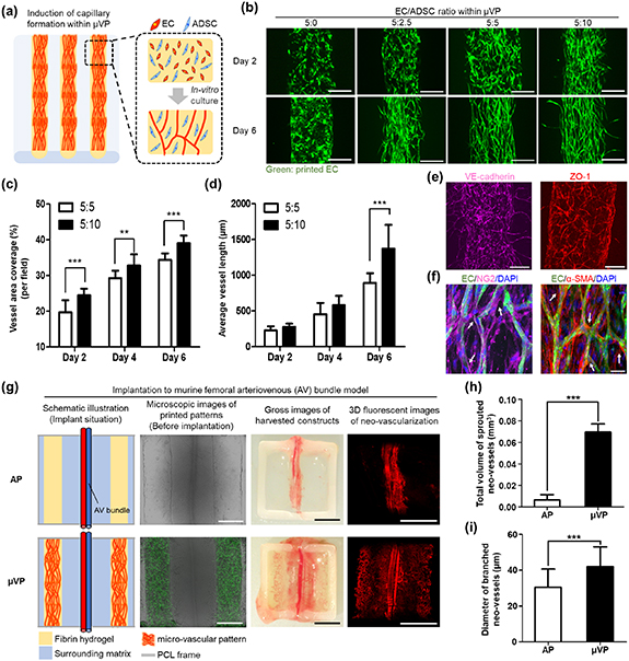
Figure 2. Formation of high density and matured μVP and in vivo functionality investigation for graft vascularization. (a) Schematic of the printed construct to induce the μVP formation, (b) fluorescent images showing the morphology of the induced μVP according to EC/ADSC ratios (5:0, 5:2.5, 5:5, 5:10—the concentration of EC in all groups is uniform at 5 × 10⁶cells ml−1) (scale bars = 250 μm). (c), (d) Quantification results of vessel area coverage and average vessel length for the 5:5 and 5:10 of EC/ADSC ratios (data represented as mean ± SD; n = 12, **p < 0.01 and ***p < 0.001, via unpaired two-tailed t-test). (e) Representative confocal z-stack images of printed μVP after seven days of culture, showing the induced micro-vessels of vascular endothelial cadherin (VE-cadherin) marker and zonula occludens-1 (ZO-1) marker (scale bars = 250 μm). (f) Confocal z-stack images of the printed μVP showing neuron-glial antigen 2 (NG2) and alpha smooth muscle actin (α-SMA) expressions. White arrows indicate the NG2 and α-SMA-expressing ADSC near the micro-vessel structure (green signal) as a function of micro-vascular pericytes (scale bars = 50 μm). (g) Graft vascularization results in two different constructs (AP: acellular patterns) after two week implantation of murine femoral AV bundle model; combined bright-field and fluorescent images illustrating the printed patterns and induced μVP after seven days of culture (scale bars = 500 μm); gross and 3D fluorescent images showing blood infiltrated vessel-like structures within the harvested constructs (scale bars = 2.5 mm). (h), (i) Quantification results of the total volume of sprouted neo-vessels and diameter of branched neo-vessels (data represented as mean ± SD; n = 4, **p < 0.01, and ***p < 0.001, via unpaired two-tailed t-test).
Download figure:
Standard image High-resolution imageTo confirm whether the capillaries formed within the µVP had in vivo-like matured characteristics, we performed the immunostaining of the printed μVP during culture. On day 7 of culture, the induced capillary network showed the formation of EC-specific adherens junctions and elongated tight junctions (figures 2(e) and S11(a)). These inter-cellular junctions are known to play a critical role in the structural functionality of matured capillaries [27, 28]. Additionally, the cultured μVP were immuno-stained using anti-neuron-glial antigen 2 (NG2) antibody and anti-α-SMA antibody (figures 2(f) and S11(b)). The proliferated ADSC (no green signal) within the μVP was confirmed to express these two markers and showed strong signals around the capillary network. Further, when EC and ADSC are co-cultured, ADSC are known to perform the role of pericytes, contributing to the stabilization of the microvascular structure [14, 24–26]. These results demonstrated that after a certain culture period (more than six days), EC can form a matured capillary network with ADSC support as perivascular cells within printed patterns.
3.2. 3D image-based analysis of in vivo neo-vascularization
We printed the constructs with acellular patterns (APs) and μVP and performed in vivo experiments with murine femoral AV bundle models (figures 2(g) and S3). The AV bundle was located at a distance from the two printed patterns (AP or μVP) across the center of the implanted constructs (shown in the schematic illustration and microscopic images of the printed patterns). After two weeks of implantation, the μVP group showed numerous micro-vessels covering a large area of the graft, easily observed with the naked eye (gross images of the harvested constructs). The 3D fluorescent images of μVP clearly showed the sprouted morphology of the AV bundle and neo-vascularization results within the harvested constructs (shown in the 3D neo-vascularization fluorescent images). Conversely, only a few short neo-vascular morphologies were identified around the AV bundle in the AP group. To compare neo-vessel infiltration into the implants more precisely, we generated 3D volumetric rendered images (figure S12) and quantified the total volume of sprouted neo-vessels and diameter of the branched neo-vessels based on the volumetric images (figures 2(h) and (i)). The μVP group (0.070 ± 0.008 mm3) showed approximately 11 times higher sprouted neo-vessel volume than the AP group (0.006 ± 0.005 mm3) (figure 2(h)). The diameter of the branched neo-vessel in the μVP group (42.06 ± 10.95 μm) was also significantly thicker than the neo-vessel diameter in the AP group (30.05 ± 10.14 μm) (figure 2(i)). These results showed that the μVP placed besides the AV bundle induced significantly increased neo-vascularization into the implants than AP.
3.3. Investigation of patterning effects of pre-vascularized constructs on graft vascularization
We investigated whether accelerated graft vascularization could be induced by controlling the designs of μVP considering the location of the host vessel (AV bundle). Pre-vascularized constructs with three different designs (μVP-Proximal, μVP-Distal, and μVP-Combined) were printed and implanted to the AV bundle model (figure 3(a)). A previous study has reported that pre-vasculature can integrate with the nearby host vasculature by remodeling the implanted EC activity [29]. The μVP-Proximal group was designed with two μVP close to the host vessel (AV bundle) to focus on the promotion of this anastomosis phenomenon. In vivo neo-vascularization (or angiogenesis) has also been reported to be guided in the direction of the concentration gradient of angiogenic factors and infiltrated into the grafts [30–32]. The μVP-Distal group is designed to facilitate the guiding effect of host vessel infiltration through continuous angiogenic factor secretion by placing the μVP away from the AV bundle. The μVP-Combined group is a combined design of the two groups that can simultaneously have both the effects described previously. We printed the pre-vascularized constructs in the desired designs and cultured them for capillary maturation. As previously confirmed, EC within the μVP showed active sprouting morphologies on day 2 (figure S13(a)) and formation of high-density capillary networks in each group was observed on the pre-implantation date (day 7) (figure 3(b)). Also, SEM images showed the microstructures with different densities of fibrin fibers between the surrounding matrix and AP, and elongated cells were placed on the fibrin fibers within μVP (figure S13(b)). Different neo-vascularization results of two week implantations were obtained when observing the harvested constructs (figure 3(c)). Several constructs of μVP-Proximal and Distal groups showed the thick branched vessels extending from the AV bundle, while some μVP-Combined group samples were primarily covered with matured blood vessels and capillaries. Considering these variances of in vivo results, we evaluated the neo-vascularization score based on the microscopic images of the harvested constructs (figure 3(d)). Score 2, which shows neo-vessel coverage of 50%–75%, appeared at similar rates in all groups. However, Score 3, which shows neo-vascularization in the widest area, could only be observed in the μVP-Proximal group and Combined groups. To precisely compare neo-vascularization of each group, we performed 3D imaging and volumetric quantification of the infiltrated blood vessels (figure 3(e)). In the μVP-Proximal group, AV bundles with several thick branched vessels were observed, similar to the gross images. The μVP-Distal group showed that a wider distribution of capillary shapes than the μVP-Proximal group. In the 3D image of the μVP-Combined group, almost all areas of the graft were covered with capillaries and numerous thick branched vessels were observed. The 3D volumetric images of each group were obtained by rendering previous fluorescent images (figure S12), and the total volume of the sprouted neo-vessels was quantified (figure 3(f)). Additionally, the neo-vessel volume of the μVP-Distal group (0.119 ± 0.023 mm3) was 2.6 times higher than that of the μVP-Proximal group (0.045 ± 0.011 mm3). The neo-vessel volume of 0.238 ± 0.037 mm3 of the μVP-Combined group was approximately 1.9 times higher than that of the μVP-Distal group. The difference also showed statistical significance. The branched vessel diameter resulting from the AV bundle surprisingly showed similar values (around 54 μm) in all groups (figure 3(g)). Further, branched vessels with similar diameters were confirmed to be formed, regardless of the μVP designs.
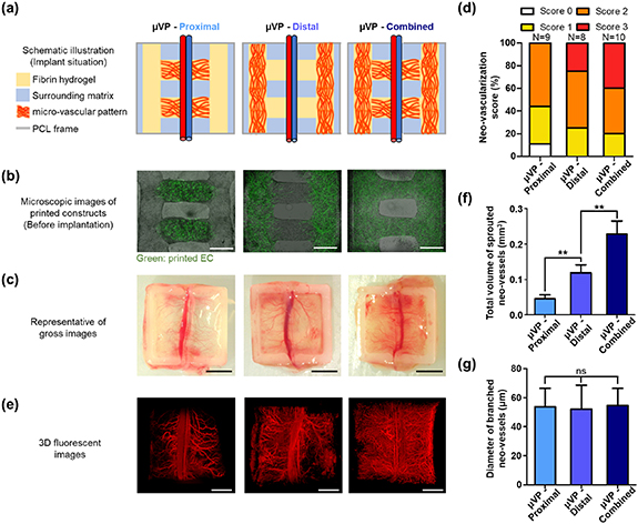
Figure 3. Pattern effect of pre-vascularized constructs on graft vascularization. μVP—proximal: micro-vascular patterns proximally located to the host vessel, μVP—distal: micro-vascular patterns distally located to the host vessel, μVP—combined: μVP—proximal + μVP—distal (a) implantation schematic of the printed constructs in the murine femoral AV bundle model. (b) Merged bright-field and fluorescent images showing the printed patterns and induced μVP after seven days of culture (scale bars = 500 μm). (c) Gross images showing the results of neo-vascularization (scale bars = 2.5 mm). (d) Fraction ratio of vascularization score from the femoral AV bundle based on the gross images of harvested constructs with different μVP designs. (e) 3D fluorescent images of blood infiltrated vessel-like structures within the implanted constructs (scale bars = 1 mm). (f), (g) Quantification results of the total volume of sprouted neo-vessels and diameter of branched neo-vessels (data represented as mean ± SD; n = 4, *p < 0.05, **p < 0.01, and ns: not significant, via one-way ANOVA followed Tukey's multiple comparisons test).
Download figure:
Standard image High-resolution imageTo verify the volumetric quantification results, we analyzed immunohistochemistry as a conventional method for neo-vascularization quantification. Harvested constructs in all the groups were sectioned in a region approximately 500 μm from the AV bundle to demonstrate similar host angiogenic responses (figure S14). Then, immunohistochemical staining with mouse-specific anti-CD31 and anti-α-SMA was performed to observe the infiltrated host vessels within the constructs (figure 4(a)). The μVP-Distal and Combined groups showed more capillary morphologies (mCD31 positive) and arterioles (α-SMA positive) compared to the μVP-Proximal group. Quantification based on immune-histological images (figures 4(b)–(d)) also showed similar neo-vascularization trends in each group compared with previous volumetric quantification results (figures 3(e) and (f)). All the quantification results (densities and diameters of stained vessels) showed an increasing trend in the order of μVP-Proximal, Distal, and Combined groups. Moreover, statistical significance between the groups was consistently confirmed. To summarize, based on two quantitative results (3D imaging and immune-histochemistry), the μVP-Distal group was confirmed to show higher neo-vascularization than the μVP-Proximal group, and the μVP-Combined group with both patterns could promote remarkable graft vascularization.

Figure 4. Immuno-histochemical analysis of neo-vascularization and computational simulation of VEGF gradient within the implanted constructs with different μVP. (a) Representative images of constructs with double-immunostaining of α-SMA/mCD31/DAPI (scale bars = 50 μm). (b)–(d) Quantification results of capillary density, arteriole density, and arteriole diameter, respectively. (e) 2D distribution of VEGF within the constructs. (f) VEGF concentration profiles along the x-coordinate of the dotted white lines in images of surface plots.
Download figure:
Standard image High-resolution imageThe significant differences in the in vivo neo-vascularization results of the three groups were hypothesized to be related to the paracrine effect of the angiogenic factors secreted by the different μVP designs. We first verified the VEGF concentration of the pre-vascularized constructs during culture to estimate the μVP secreting ability (figure S8(a)). The VEGF concentration of the constructs with μVP on day 6 (timeline of implantation) was approximately 202.60 ± 70.08 pg ml−1, which showed a lower value than on day 4. This may be due to the differentiation of the ADSC present in the μVP into pericyte-like cells during culture, thereby reducing their secreting ability (figure 2(f)) [33]. Then, we performed computational simulation analysis with the estimated VEGF secreting rate of μVP to investigate the concentration gradients of the angiogenic factors within the constructs of each group. The simulation results showed the distribution of high VEGF concentration (indicated in red) around the μVP regions (figure 4(e)), similar to the printed design of each group (figures 3(a) and (b)). The μVP-Distal group created an environment wherein VEGF diffused from the μVP at both ends to the central region (where the AV bundle is located) along the acellular hydrogel pattern. Conversely, the μVP-Proximal group showed opposite VEGF gradient results. The μVP-Combined group had a higher VEGF concentration within the μVP regions than the two groups, and a slightly lower concentration in the central part of the horizontal μVP. To analyze the VEGF concentration gradient for neo-vascularization from the AV bundle, we analyzed the VEGF concentration profile along the horizontal pattern (indicated with white dotted lines) of each design (figure 4(f)). In contrast to the μVP-Proximal group, the μVP-Distal group formed a VEGF gradient that increased from the center (3 mm of x-coordinate) to both ends. In addition, the μVP-Combined group showed a similar but larger VEGF gradient to the μVP-Distal group. The formation of an angiogenic factor gradient, which increases from a low to high concentration, is known to be a critical parameter for inducing angiogenic response [30–32]. Based on these simulation results, the angiogenic factor concentration gradient formed by the design of μVP-Distal and Combined groups was confirmed to promote neo-vascularization compared to the μVP-Proximal group.
3.4. Synergetic effect of μVP and AMP on graft vascularization
The robust graft vascularization was hypothesized to be obtained if angiogenic factor gradient formation was further optimized in the μVP-combined group design. Hence, we investigated bio-ink conditions for patterns with increased secretion of angiogenic factors than μVP. Previous results confirmed that VEGF secretion of μVP tended to decrease in the six day cultures (figure S8(a)), and the VEGF secretion ability of the patterns containing ADSC alone (10, 20 × 106cells ml−1 of ADSC; indicated as A10, A20) was evaluated. Surprisingly, despite the same concentration of ADSC, A10 showed 1.5-fold higher VEGF secretion than μVP (figure S8(b)). Moreover, A20 showed approximately four times higher VEGF secretion than μVP. These results are consistent with studies showing higher VEGF secretion in single ADSC cultures than in a combination of EC and ADSC [34, 35]. Therefore, we determined the AMP as the ideal condition for A20 and devised our novel pre-vascularized construct (figure 5(a)). μVP was paced close to the host vessel to focus the vascular integration ability, whereas AMP was placed away from the host vessel to form an angiogenic factor gradient. Using the synergetic effect of these two patterns, robust graft vascularization is expected to be achieved compared to previous results.

Figure 5. Bioprinting of pre-vascularized construct with synergetic patterns (μVP and AMP) to enhance neo-vascularization. (a) Schematic of pre-vascularized constructs with two different patterning, and the mechanism of neo-vascularization induction in each pattern from the neighboring vessels. (b) Implantation schematic of the printed constructs in the murine femoral AV bundle model. (c) 3D fluorescent and rendered images of blood infiltrated vessel-like structures within the implanted constructs (scale bars = 2 mm). (d) Fraction ratio of vascularization score from the femoral AV bundle based on the gross images of the harvested constructs. (e), (f) Quantification results of the total volume of sprouted neo-vessels, and the diameter of branched neo-vessels (data represented as mean ± SD; n = 4, **p < 0.01 and ***p < 0.001, via one-way ANOVA followed by Tukey's multiple comparisons test).
Download figure:
Standard image High-resolution imageTo demonstrate this synergetic effect, we investigated the in vivo neo-vascularization results in three different designs (μVP only, AMP only, μVP + AMP) of printed constructs (figure 5(b)). The μVP only group is the same design as the μVP-Combined group that showed the most effective results in the previous experiments (figures 3 and 4). The AMP only group was designed to create a similar angiogenic factor concentration gradient environment and adjust the total amount of ADSC with μVP + AMP group. The AMP with low density (A10) were placed near the host vessels and AMP with high density (A20; same patterns within μVP + AMP group) were printed parallel to the blood vessels. As expected, the VEGF simulation results showed that the AMP only and μVP + AMP groups had a higher VEGF concentration within the entire printed patterns than the μVP only group, and yellow colored (relatively lower VEGF concentration) horizontal patterns were observed in both groups (figure S15(b)). Also, the VEGF concentration profiles along the x-coordinate illustrate the significant differences in the concentration gradient (figure S15(c)). These results confirmed that the new designs with AMP printing can enhance the angiogenic function of our printed constructs. All three groups induced the high vascularization results after two week implantation, but the AMP-only group showed an overall shorter sprouting neo-vascular morphology (figure 5(c)). Comparing the neo-vascularization score of each group, the samples from the μVP + AMP group showed high scores more frequently (figure 5(d)). The proportion of neo-vascularization with a score of 3 was 40%, 27%, and 70% for the μVP only, AMP only, and μVP + AMP groups, respectively. The quantification of total sprouted neo-vessel volume was 0.335 ± 0.022 mm3 for the μVP + AMP group, 1.5- and 1.9-fold higher than the μVP only and AMP only groups, respectively (figure 5(e)). Moreover, the branched vessel diameter of the μVP + AMP group was significantly higher (72.07 ± 14.46 μm) than two other groups (figure 5(f)), identified by the clear differences in morphologies of the branched vessels with the 3D imaging results (figure 5(c)).
We also performed immuno-histological analysis on both groups. The μVP + AMP group showed significantly more mCD31-positive and α-SMA-positive vessels than the μVP only group and AMP only group (figure 6(a)). The quantitative results also demonstrated differences in vessel density and statistical significances between the two groups (figures 6(b) and (c)). Additionally, the diameter of the α-SMA-positive vessel was approximately 1.7 times higher for the μVP + AMP group (44.75 ± 9.64 μm) than the μVP only group and AMP only group (figure 6(d)). Lastly, the harvested constructs were immuno-stained with anti-hCD31 antibody to observe the implanted capillary network (composed of human EC) after transplantation (figure 6(e)). A large number of hCD31-positive vessels were identified within the μVP region of the implant, and some vessels with relatively large lumens (yellow arrows in the fluorescent image) were located in the same positions with vessel-like structures including red blood cells (H&E image). These blood-perfused vessel structures are expected to result from the vascular integration between the engineered and host vasculatures reported in various studies [13, 14, 36–39]. We also confirmed the in vivo potency of μVP located nearby the AV bundle by observing the vessel-like structures composed of implanted EC. In addition, although both groups (AMP only and μVP + AMP groups) can generate a similar VEGF gradient environment (figure S15), this result indicates that the positioning of μVP adjacent to the host vessels can be a critical factor for robust graft vascularization. To summarize, these results clearly indicated that the implantation of pre-vascularized constructs with μVP and AMP guided robust graft vascularization with synergetic effects of the two printing patterns.

Figure 6. Immuno-histochemical analysis of the implanted constructs to investigate the synergetic effects of μVP + AMP on graft vascularization. (a) Representative images of the construct with immunostaining of α-SMA/mCD31/DAPI (scale bars = 50 μm). (b)–(d) Quantification results of capillary density, arteriole density, and arteriole diameter respectively. (e) H&E (left) and immuno-histological images with hCD31/DAPI staining (right) show red blood cells perfused micro-vessels and vessel-like structures implanted ECs within the implanted construct (μVP + AMP). Yellow arrows indicate vessel-like structures in similar locations of both images (scale bars = 50 μm).
Download figure:
Standard image High-resolution image
4. Discussion
A pre-vascularization strategy is reportedly beneficial for inducing in vivo vascularization in implanted constructs [11–19, 36–39]. Recently, the implantation of scaffolds with aligned vascular patterns has been reported to promote graft vascularization and lead to enhanced viability and functionality of the engrafted parenchymal cells (e.g. hepatocytes or islets) [18, 19]. However, only the effect of organized vascular patterns has been demonstrated, and the impact of pre-vascularized patterns on in vivo neo-vascularization has not been elucidated. Therefore, we analyzed the neo-vascularization results based on the design of μVP using the AV bundle model (which allowed fixing the location of the host vessels) (figure 3(a)). Based on the quantification via 3D imaging and immuno-histochemistry, the μVP-Distal group was confirmed to induce more neo-vascularization than the μVP-Proximal and Combined groups (combined design of the two groups), leading to the most effective results (figures 3 and 4(a)–(d)). The computational simulation results revealed the angiogenic factor concentration gradient of the by different μVP designs, which provide details of the effect of the patterns on neo-vascularization (figures 4(e) and (f)). Based on these results, we developed a novel pre-vascularized construct using AMP to improve paracrine functionality (figures 5(a) and S15). Consequently, the pre-vascularized constructs of the new design (μVP + AMP) showed improved in vivo neo-vascularization results than the μVP only and AMP only constructs (figures 5 and 6). To summarize, we developed a novel strategy to fabricate the proposed pre-vascularized construct with two synergetic patterns (μVP and AMP) and verified its effectiveness for graft vascularization. We believe that our developed method can be used as a practical pre-vascularization method to promote the engraftment of volumetric engineered tissues.
We developed a method for printing high density μVP with mature capillaries (figures 2(a)–(f)). Several studies have used EC and ADSC (or other tissue-derived mesenchymal stem cells) co-cultures for in vitro vascular formation and introduced the positive aspects of in vivo vascularization into these pre-vascularized grafts [13, 14, 24–26, 36–39]. Baranski et al [13] demonstrated that the formation of high-density µVPs with in vitro cultures can promote host vessel infiltration into the grafts. We also used a specific EC/ADSC ratio and sufficient culture time before implantation to form the dense capillaries in μVP (figures 2(b)–(d)). This may have contributed robust graft vascularization upon implantation (figures 3–6). Several studies suggested that ADSC exhibits peri-vascular cell-like characteristics for the stabilization of the matured vascular structures during micro-vascular network formation [14, 24–26]. In our results, the induced capillaries expressed the tight inter-cellular junction marker (indicates the matured characteristics) (figure 2(e)), and ADSC presence around the micro-vessel structures strongly expressed pericyte markers. (figure 2(f)). Recent studies reported that the implantation of scaffolds containing matured micro-vascular networks promote graft vascularization [36, 37]. This conclusion is in good agreement with the results obtained in the current study, which highlights that the matured capillaries with enough culture time of EC and ADSC had a beneficial effect on the in vivo results.
The pattern effect of μVP on in vivo neo-vascularization was confirmed using the AV bundle model and 3D imaging-based quantification (figure 3). Various transplantation sites in the murine model (dorsal subcutaneous tissue, hindlimb tissue, greater omentum, etc) are typically used to analyze neo-vascularization functionality [40, 41]. However, the host tissues have been reported to show randomized vasculature, leading to varied graft vascularization results depending on the implantation sites [42]. Hence, the AV bundle model is a method of inducing intrinsic vascularization by placing host macro-vessels inside the graft [21]. Using this model is expected to allow the designing of the experiments to define the location of host blood vessels (AV bundles) and analyze the patterning effect of μVP accordingly. The AV bundle was fixed at the center of the structure through via printed frame structure, and the isolated environment from the surrounding host tissues was generated by wrapping them with a medical silicone sheet (figure S3). After the implantation period, the printed constructs were easily harvested and the neo-vascularization results were clearly observed from AV bundle (figure S4). Additionally, immune-histological analysis has been used as a general tool for quantifying the vascularization of implanted constructs [40, 41]. However, we gauged that 2D sectional views were not sufficient to analyze the vascularization result within 3D structures. Hence, tissue clearing was performed on the harvested implant, enabling its visualization as a 3D volumetric image of blood vessels containing host blood (figure S6). Consequently, 3D images of the graft vascularization results were observed based on μVP design and quantitatively analyzed for neo-vascularization (figures 3(e)–(g)). Additionally, by confirming similar neo-vascularization tendencies with histological analysis, the reliability of our 3D image-based quantification methodology was confirmed (figures 4(a)–(d)). Hence, our implantation model and vascular quantification method is expected to be utilized for the evaluation of the angiogenic functionality of printed 3D artificial tissues, including cells andJ biomaterials.
A novel pre-vascularized construct capable of inducing robust in vivo neo-vascularization from host vasculature was developed. Recently, many papers introduced organized vasculature implantation to induce neo-vascularization and regenerative effects in the ischemic regions [14, 43–45]. Kang et al [14] fabricated an implant containing EC/ADSC co-aligned patterns and demonstrated therapeutic effects in a critical peripheral ischemic model. Mirabella et al [44] reported rapid blood flow recovery effect of parallel patterned EC channels compared to other patterns. However, these studies confirmed a therapeutic effect on the ischemic region of the implant considering only micro-vasculature patterning. However, based on our analysis, these grafts containing only organized vasculature may have lacked paracrine functionality (figures 5 and 6). In addition, our results showed that pre-vascularized patterns near the host vessel can integrate with host vasculature (figure 6(e)), and implants with dual patterns induce higher graft vascularization than constructs without EC even though both printed constructs (AMP only and μVP + AMP groups) can create a similar VEGF gradient (figure S15). We believe that optimization of pre-vascularized patterns and paracrine functionality considering existing host vasculature should be simultaneously performed for the vascularization of scaled-up constructs. Additionally, if our pre-vascularized constructs using μVP and AMP are applied to ischemic therapy, we expect that our pre-vascularized constructs can induce enhanced therapeutic efficacy. As a follow-up study, functional implants will be developed with effective regenerative abilities for ischemic diseases through parameter studies between the two patterns.
5. Conclusion
In this study, pre-vascularized construct designs were developed to including synergetic printing patterns (μVP and AMP) capable of promoting graft vascularization. Printing conditions were established to induce high-density mature capillary formation within the printed μVP, and the pattern effect of μVP on in vivo neo-vascularization with AV bundle model implantation was confirmed. Finally, pre-vascularized constructs using μVP and AMP were designed to improve paracrine functionality, and effectiveness of synergetic dual patterns for graft vascularization promotion was confirmed via implantation experiments. Our method is believed to be used as an efficient pre-vascularization strategy for achieving rapid vascularization of scaled-up artificial tissues and develop functional implants for ischemic diseases.
Acknowledgments
J S and H-W K designed the research project. J S, H J M, A N, and H-W K drafted and revised the manuscript. J S performed in vitro analysis for micro-vascular formation and computational analysis. J S, H J M and W H conducted all animal experiments. J S and H-C J conducted 3D image-based analysis. J S and H J M performed immuno-histological analysis. C A C, Y K, and S P contributed to the establishment of animal models and analysis of neo-vascularization results. The authors thank Hyeon Seo Kim (Department of Biomedical Engineering, UNIST) for assistance with harvest of implants. This research was supported by the National R&D Program through the National Research Foundation of Korea (NRF) funded by the Ministry of Science and ICT (NRF-2020M3H4A1A02084827). Additionally, this research was financially supported by the Institute of Civil Military Technology Cooperation funded by the Defense Acquisition Program Administration and Ministry of Trade, Industry and Energy of the Korean government under Grant No. 22-CM-BR-12
Data availability statement
The data cannot be made publicly available upon publication because they are not available in a format that is sufficiently accessible or reusable by other researchers. The data that support the findings of this study are available upon reasonable request from the authors.
Conflict of interest
The authors declare no conflict of interest.
Supplementary data (2.1 MB PDF)