
Abstract
The tissue engineering applications of coaxial electrospinning are growing due to the potential increased functionality of the fibres compared to basic electrospinning. Previous studies of core and shell scaffolds have placed the active elements in the core, however, the surface response to a biomaterial affects the subsequent behaviour, thus here hydroxyapatite (HA) was added to the shell. Coaxial electrospun polycaprolactone (PCL)-polylactic acid (PLA)/HA (core–shell) scaffolds were produced in 2D sheets using a plate collector, or 3D tubes for bone tissue engineering using a rotating needle collector. The scaffolds include high hydroxyapatite content while retaining their structural and mechanical integrity. The effect of the collector type on fibre diameter, fibre alignment and mechanical properties have been evaluated, and the impact of HA incorporation on bioactivity, BMP-2 release, cell behaviour and mechanical properties for up to 12 weeks degradation were assessed. Fibre uniformity in coaxial electrospinning depends on the relative flow rate of the core and shell solutions. Using a rotating needle collector increased fibre alignment compared to a stationary collector, without affecting fibre diameter significantly, while HA content increased fibre non-uniformity. Coaxial PCL-PLA/HA fibres exhibited significantly higher bioactivity compared to PCL-PLA scaffolds due to the surface exposure of the HA particles. Apatite formation increased with increasing SBF immersion time. Coaxial tubular scaffolds with and without HA incorporation showed gradual reductions in their mechanical properties over 12 weeks in PBS or SBF but still retained their structural integrity. Coaxial scaffolds with and without HA exhibited gradual and sustained BMP-2 release and supported MSCs proliferation and differentiation with no significant difference between the two scaffolds types. These materials therefore show potential applications as bone tissue engineering scaffolds.
Export citation and abstract BibTeX RIS

Original content from this work may be used under the terms of the Creative Commons Attribution 3.0 licence. Any further distribution of this work must maintain attribution to the author(s) and the title of the work, journal citation and DOI.
1. Introduction
Numerous synthetic bone graft substitutes have been developed to overcome the problems associated with using autografts and allografts, which includes limited supply, donor site complications and the risk of disease transmission and immune rejection. Polymer-based biomaterials can be fabricated into a variety of structures with acceptable mechanical properties, topography, geometry and architecture for multiple biomedical applications. However, usually they have too low bioactivity for bone formation. Therefore the incorporation of bioactive fillers into polymers matrices is used to increase their bioactivity [1, 2]. Calcium phosphate ceramics (CaPs), such as hydroxyapatite (HA), tricalcium phosphate (TCP) and biphasic calcium phosphate (BCP), are commonly added as fillers to polymers due to their resemblance to the natural inorganic component of bone and their osteoconductive properties. Additionally incorporation of calcium phosphate fillers can both stiffen and strengthen low modulus and low strength polymers [3].
Among various scaffold fabrication techniques, electrospinning has been extensively investigated over the last two decades as it is a relatively simple and low-cost method to produce fibrous scaffolds from polymeric solutions with diameters ranging from nano- to micro-scale that mimic extracellular matrix (ECM) of the native tissue [4]. A variety of natural and synthetic polymers have been used to produce electrospun scaffolds for bone tissue engineering and have been reinforced with calcium phosphates, bioglasses, or glass-ceramics. However, one of the major problems associated with increasing filler incorporation is the significant reduction of the mechanical properties due to the brittleness of the ceramic fillers in general, bead formation along the fibres and the lack of interfacial bonding between the polymer matrix and the filler. One method of improving the mechanical properties is using electrospinning where two dissimilar materials are delivered independently through a coaxial needle to form fibres with core and shell configuration.
In this study, micron-sized sintered HA was investigated for electrospinning with PLA as the shell component for the coaxial scaffolds to improve the bioactivity and osteoconductivity while PCL was selected as the core to provide the mechanical stability to the scaffolds. These two polymers were chosen to give a slower degrading and more ductile core with a relatively faster degrading outer layer. The addition of HA to the shell phase was expected to affect the degradation of both polymers as both degrade acidically, whereas the breakdown products of HA are basic and thus moderate acidic degradation [3]. The two polymers are compatible and the same solvent was used thus a good interface between the core and shell was expected.
Modification of an electrospinning collector is a common method to produce 3D electrospun scaffolds for tissue engineering applications. For many tissue engineering applications, tubular scaffolds are fundamental as they imitate anatomical structures in the body. They are employed in clinical applications such as nerve guides and bone defects [5]. Thus, this study aims to produce bioactive tubular scaffolds of core and shell fibres via coaxial electrospinning and a rotating needle collector.
2. Materials and methods
2.1. Materials
Polylactic acid (Ingeo Biopolymer 3001D PLA) with 136 000 g mol−1 average molecular weight (Mw) [6], 1.5% D-lactide content and 1.24 g cm−3 density was supplied by NatureWorks LLC (Minnetonka, USA). Polycaprolactone (PCL) with 80 000 g mol−1 average number molecular weight and 1.145 g cm−3 density was obtained from Sigma-Aldrich, UK. Sintered hydroxyapatite (HA P220S, d50 = 3.59 μm) with specific surface area of 0.965 m2 g−1 and a theoretical density of 3.162 g cm−3 was obtained from Plasma Biotal Ltd, UK. The solvent used to prepare both polymeric solutions was a 2:1 chloroform:acetone mixture, using chloroform, 99.8+%, certified AR for analysis and stabilised with amylene and acetone, 99.5+% (both Fisher Scientific, UK).
2.2. Electrospinning solutions preparation
To prepare the core solution, PCL was dissolved in the chloroform:acetone mixture at 40 °C to give a concentration of 20% (wt/v), while the shell solution was prepared by dissolving PLA in the chloroform:acetone mixture at room temperature to give 15% (wt/v) PLA solution. HA was then added to the PLA solution to give 20 vol% (38.9 wt%) in the final composite shell layer. The PLA/HA solution was mixed for 30 min, followed by placing in an ultrasound bath for at least 15 min to ensure that the filler was well distributed throughout the solution. After mixing and sonication the solutions were placed in the syringes and electrospinning started.
2.3. Fabrication of scaffolds
Coaxial electrospinning was performed using a horizontal setup (figure 1). Two programmable syringe pump modules (Spraybase, Dublin, Ireland) were used to deliver the shell and core solutions. The two solutions were fed to a coaxial needle (16 G inner diameter, 11 G outer diameter, figure 1(a)) via PTFE tubes (Spraybase, Dublin, Ireland). Solutions were electrospun using 13.7 kV voltage and tip-to-collector distance of 20 cm. The flow rate of the shell solution was fixed at 3 ml h−1, while the core flow rate was set at either 2 or 3 ml h−1 to give 2:3 or 3:3 flow rate ratios.
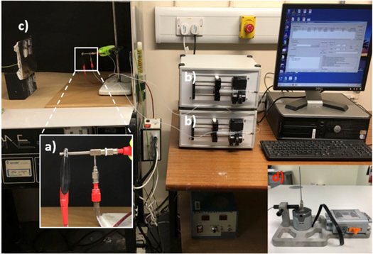
Figure 1. Coaxial electrospinning setup showing (a) the coaxial needle, (b) the two syringes mounted in their pumps, with either (c) the plain collector and (d) the rotating needle collector.
Download figure:
Standard image High-resolution imageThe 2D scaffolds were collected on standard microscope slides (75 × 25 mm) (figure 1(c)) while the 3D tubes were collected on a custom built rotating needle collector (figure 1(d)) manufactured using a LEGO power functions XL-motor (Billund, Denmark) (rotation speed 220 rpm) and G16 (OD = 1.35 mm) or G21 (OD = 0.67 mm) stainless steel collector needles. Prior to electrospinning, the collector needles were sprayed with anti-adhesive PTFE spray and left to dry for 10–15 min before electrospinning. The finished electrospun tubes were left to dry for 15–20 min after electrospinning before extracting them gently from the collector. Dual core scaffolds, but without HA, manufactured under the same conditions, were used as controls.
2.4. Characterisation of electrospun scaffolds
2.4.1. Structural and morphological characterisation
The morphology of the electrospun scaffolds was observed using scanning electron microscopy (SEM, JOEL JSM-6400, Tokyo, Japan) at 10 kV. Control and HA containing sheets and tubes were cut into small pieces and mounted on aluminium stubs using double-sided conductive carbon adhesive tape. The specimens were sputter coated with a thin (<20 nm) layer of gold-palladium using a Quorum Q150T ES (Quorum, East Sussex, UK). The average fibre diameter for each scaffold type was calculated by analysing at least 50 fibres from three different SEM images using ImageJ software (NIH, USA). Fibre orientation was measured using the SEM images and MATLAB software. The total porosity of the scaffolds was calculated using a gravimetric method, the specimens were weighed and the dimensions of the scaffolds were measured. The bulk density of the coaxial scaffolds were calculated to be 1.19 and 1.30 g cm−3 for control and HA containing scaffolds.
Different methods were employed to identify the core and shell structure within the coaxial fibres: firstly, electrospun sheets were placed into liquid nitrogen and manually broken prior to sputter coating to observe cross sections of the fibres. Secondly, small square pieces were cut from the scaffolds and embedded in Epon resin (Hexion, Columbus, OH, USA) before slicing into thin (∼70 nm thick) sections using a Leica ultracut UCT ultramicrotome (Leica, Vienna, Austria). The thin sections were collected on TEM copper grids and imaged using a JOEL 1200 EX II transmission electron microscope (JOEL, Tokyo, Japan) at 80 kV. Lastly, rhodamine B and FITC dyes were added to the core and shell solutions respectively prior to electrospinning and mixed for about 1 h to ensure homogeneity. Aluminium foil was wrapped around the solution containers to protect them from light. Samples were observed using a LSM880 inverted confocal microscope with Airyscan (Carl Zeiss, Jena, Germany) with 20×, 40× and 63 × objectives. A 488 nm laser was used to excite the FITC labelled shell and collect the resulting fluorescence, while a 561 nm laser was used to excite the rhodamine B labelled core. Images were acquired and analysed using ZEN Black software (Carl Zeiss, Jena, Germany).
2.5. Biodegradation and bioactivity measurements
To evaluate the dissolution rate and bioactivity of the control and HA containing scaffolds, samples were immersed in either phosphate buffered saline (PBS) or simulated body fluid (c-SBF) at 37 °C for up to12 weeks. PBS solution (pH 7.4) was prepared by dissolving PBS tablets (Gibco™) in distilled water. c-SBF were prepared following the method described by Oyane et al [7]. The solutions were changed every 7 d. Six samples of each scaffold type (n = 6) were extracted after 4, 8, or 12 weeks to measure their water uptake and weight loss. After each degradation time, samples were taken out of the solution, washed carefully and thoroughly in distilled water and blotted gently with a paper towel to remove excess water prior to weighing. After measuring the wet weights, samples were dried for 48 h in a desiccator and re-weighed.
Apatite formation on the surface of fibres was detected using a Carl Zeiss Sigma variable pressure analytical SEM at 20 kV equipped with Oxford microanalysis EDX system (Jena, Germany). Three samples (n = 3) of both control and HA containing tubes were measured at each time point.
2.5.1. Mechanical testing
The tensile mechanical properties were measured. For 2D sheets, test samples were cut to 10 mm by 60 mm to provide a 40 mm test gauge length (reduced size ISO 13934), while for the 3D tubular scaffolds, tubes electrospun on to G16 needles were cut to 60 mm to give 40 mm gauge length for mechanical testing. Testing using a Zwick/Roell Z2.0 (Zwick Roell, Leominster, UK) test machine with a 5 N load cell operating at 3 mm min−1 and running Zwick/Roell TestXpert® software. Five samples were tested for each group. Young's modulus, ultimate tensile strength and strain at failure were calculated, before or after immersion in either PBS or SBF.
2.5.2. Measurement of BMP-2 release
The release of recombinant human BMP-2 from the co-electrospun control and HA containing sheets in vitro was quantified via enzyme-linked immunosorbent assay (ELISA). 15 mm diameter circular samples were placed in 24-well plates. BMP-2 was dissolved in PBS at concentration of 50 ng ml−1 and then a 250 μl drop placed on the surface of the samples, which were allowed to dry overnight at room temperature. The next day, the samples were placed in new wells and 1 ml of PBS was added to each membrane. At time points between 15 min and 4 d, the PBS was collected and stored at −20 °C until analysis, and the scaffold was re-incubated in 1 ml fresh PBS. The concentration of BMP-2 in the collected PBS was measured using an ELISA kit following the protocol provided by the manufacturer (R&D Systems, Inc., Minneapolis, USA). Five samples (n = 5) were used for each composition and time point. The cumulative release ratio was calculated as the ratio of the cumulative amount released during each time interval to the initial amount placed on the scaffold.
2.5.3. Human mesenchymal stem cell (MSC) adhesion and morphology
Coaxial control and HA containing sheets were used for cell adhesion studies. Scaffolds were sterilised by soaking in an 80% ethanol solution, washed several times in sterile PBS and finally soaked in Dulbecco's modified Eagle's medium supplemented with 10% fetal bovine serum, 110 mg l−1 sodium pyruvate, 1000 mg l−1 glucose, 100 U ml−1 penicillin, 100 μg ml−1 streptomycin and 0.25 μg ml−1 amphotericin, 2 mM l−1 glutamine (expansion media). Prior to cell seeding, scaffolds were cut under sterile conditions to fit the wells of standard 24-well culture plates. Human MSCs (Promocell, UK) were expanded under standard culture conditions (5 % CO2 and 37 °C) and cells up to passage three used. Scaffolds were seeded at a density of 4000 cells cm−2. Cells were cultured for up to 21 d, with media changed every two days.
Cell-scaffold interactions were examined using scanning electron microscopy (SEM, JOEL JSM-6400, Tokyo, Japan). At 1, 7, 14, or 21 d cell culture the media was removed. The seeded scaffolds were washed in HEPES saline and fixed in 1.5% glutaraldehyde in 0.1 M sodium cacodylate for 1 h at 4 °C. Afterwards, the fixative solution was removed and scaffolds was submerged in 0.1 M sodium cacodylate buffer rinse for three times (5 min each). Samples were post fixed in 1% osmium tetroxide buffer for 1 h followed by three distilled water washes (10 min each) and then en bloc stained with 0.5% aqueous uranyl acetate for 1 h. Finally, scaffolds were dehydrated through an ethanol gradient and then critically point dried using a Tousimis Autosamdri-815 (MD, USA) before mounting on aluminium stubs and coating with gold-palladium.
2.5.4. MSC proliferation
To assess the effect of electrospun scaffold composition on MSC proliferation Alamar Blue assays were performed. At defined time points, the culture media was removed and cells were washed three times in warm 1 × PBS. 10% (v/v) of AlamarBlue resazurin (Bio-Rad, Watford, UK) diluted in phenol-red-free media (D5030, Sigma) was added to each scaffold. After further incubation for 4 h at 37 °C and 5% CO2, the culture supernatant was transferred into 96-well plates to measure AlamarBlue reduction indicating cell metabolism. A microplate reader (Clariostar, BMG Labtech, Germany) was used to detect light absorbance at wavelengths of 570 and 600 nm.
2.5.5. Assessment of scaffold ability to support osteogenic differentiation through quantitative real-time PCR (qRT-PCR)
To induce osteogenic differentiation of MSCs on electrospun scaffolds, expansion media was further supplemented with 100 μmol ascorbic acid (Sigma Aldrich, UK), 100 nmol dexamethasone (Sigma Aldrich, UK) and 10 mmol glycerol phosphate (Sigma Aldrich, UK) and cells were cultured for 21 d, with media changes every 2 d.
Following 21 d culture, the osteogenic differentiation of MSCs on scaffolds was assessed using qRT-PCR. Cell scaffolds were removed from culture wells and transferred to 15 ml Falcon tubes. Equal volumes of Trizol reagent (Life Technologies) was added to each sample, which were then vortexed. 0.2 ml of chloroform (Sigma Aldrich) was added per ml of Trizol to each sample, mixed and centrifuged to separate the aqueous and organic phases. The aqueous phase was removed and the total RNA content was then extracted using the Qiagen RNeasy extraction kit (including a DNAse step) according to the manufacturer's instructions (Qiagen, Hilden, Germany). The RNA concentration was quantified using the Nanodrop and normalised for each sample. cDNA was prepared by reverse transcription using the Qiagen Quantitect kit. 12 μl of the normalised dilutions for each RNA sample were added to a 0.2 ml RT–PCR tubes. To each of the samples, 2 μl gDNA wipeout buffer was added. Following this, each sample was run at 42 °C for 2 min on a thermal cycler (PCR) system to remove any DNA present in the samples. Following the removal of the innate DNA, 6 μl of a stock solution (containing Qiagen reverse transcription buffer reagents) was added to each reverse transcription Eppendorf tube, to give a total volume of 20 μl and reverse transcription of the RNA into cDNA performed. This was subsequently used to perform PCR quantification using the relative comparison method. The Quantifast SYBR green qRT-PCR kit (Qiagen) was used to perform amplification with specific primers (Eurofins Genomics, Ebersberg, Germany) related to osteogenesis as well as GAPDH, which was used as a genetic internal control. qRT-PCR products were quantified using the 2−∆∆Ct method and amplification was carried out using an Applied Biosystems 7500 Real Time PCR system. Primer sequences used in this study are listed in table 1.
Table 1. qRT-PCR primer sequences used in this study.
| Gene name | Forward primer | Reverse primer |
|---|---|---|
| GAPDH | TCAAGGCTGAGAACGGGAA | TGGGTGGCAGTGATGGCA |
| RUNX2 | GGTCAGATGCAGGCGGCCC | TACGTGTGGTAGCGCGTGGC |
| BMP2 | CTTCTAGCGTTGCTGCTTCC | AACTCGCTCAGGACCTCGT |
| ALKP | ATGAAGGAAAAGCCAAGCAG | CCACCAAATGTGAAGACGTG |
2.6. Statistical analysis
Results are expressed as mean ± standard deviation (SD) in all experiments. Statistical analysis was performed using a one- and two-way analysis of variance (ANOVA), with p-values less than 0.05 considered statistically significant, and Student's t-test was used for pairwise comparisons.
3. Results
3.1. Structure and morphology of scaffolds
Electrospinning at 2:3 and 3:3 flow rate ratios yielded uniform, non-beaded fibres (figure 2). Fibre diameters measured using ImageJ were 5.91 ± 3.47 μm and 6.06 ± 2.89 μm respectively. Figure 3(a) shows individual fibre morphology of coaxial HA containing scaffolds at 3:3 flow rate ratio while figures 3(b) and (c) show TEM images of resin embedded control and HA containing coaxial fibres electrospun at 3:3 core:shell flow rate ratio respectively. Fibres of both scaffolds exhibited core and shell structure, however, the thickness of the shell layer was variable and in some cases discontinuous. The HA containing scaffolds show HA particles protruding from the surface of the fibres (blue arrow in figure 3(b)) or into the core layer. The HA particles are brittle and fractured during the sectioning process explaining the fragments of HA surrounded by gaps seen in figure 3(b). Tubular PCL-PLA and PCL-PLA/HA co-electrospun scaffolds were fabricated using the rotating needle collector. Macroscopic and microscopic morphology of the tubular scaffolds are shown in figure 4 with the internal hole clearly visible.
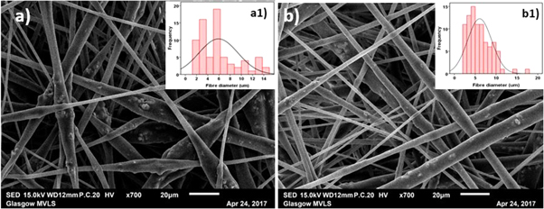
Figure 2. SEM images of core–shell PCL-PLA/HA fibres electrospun at (a) 2:3 and (c) 3:3 core:shell flow rate ratio (marker bars = 20 μm) with (a1) and (b1) showing the histograms of the fibre diameters for 2:3 and 3:3 flow rates.
Download figure:
Standard image High-resolution image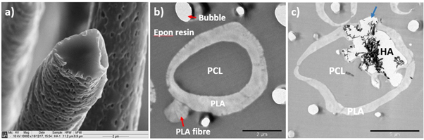
Figure 3. (a) SEM image of freeze fractured PCL-PLA/HA coaxial fibres electrospun at 3:3 core:shell flow rate ratio, (b) and (c) TEM images of resin embedded PCL-PLA and PCL-PLA/HA coaxial fibres electrospun at 3:3 core:shell flow rate ratio respectively, showing with the shell layer covering the fibre completely. Also visible are a PLA fibre with no core (red arrow) and (c) partial encapsulation of HA particles (blue arrow) (marker bars (a)) and (b) = 2 μm, (c) = 5 μm).
Download figure:
Standard image High-resolution image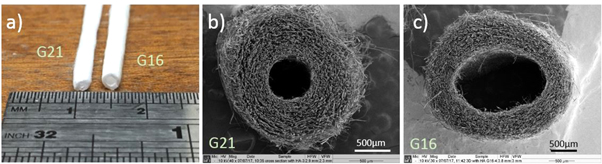
Figure 4. (a) Macroscopic and microscopic structures of the PCL-PLA/HA tubular scaffold the dimensions of the tubes, (b) and (c) SEM images of G16 and G21 tube cross sections, respectively (marker bars (b)) and (c) = 500 μm).
Download figure:
Standard image High-resolution imageFigures 5 and 6 show the morphologies of electrospun control and HA containing tube scaffolds and 2D sheets, respectively, along with their fibre alignment patterns and fibre diameter distribution curves. The tubular scaffolds all had increased fibre alignment compared to their 2D coaxial sheets equivalents, as can be seen in both figures 5 and 6 by comparing (B2) and (B3) with (B1). The fibres in the all control scaffolds and the 2D HA containing scaffolds had more uniform diameters with lower SDs than for the HA containing tubes (table 2), however, but the changes in porosity are not significant, with all the porosities high enough to expect good tissue ingrowth.
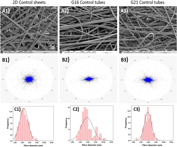
Figure 5. SEM micrographs of control (A1) 2D sheets, (A2) G16 tubular scaffolds, and (A3) G21 tubular scaffolds (marker bars = 20 μm for A1 and 50 μm for (A2) and (A3). (B) The calculated fibre alignment pattern for control (B1) 2D sheets, (B2) G16 tubular grafts, and (B3) G21 tubular grafts. (C1)–(C3) Shows the fibre diameter distribution in the 2D sheets, G16, and G21 tubular scaffolds, respectively.
Download figure:
Standard image High-resolution image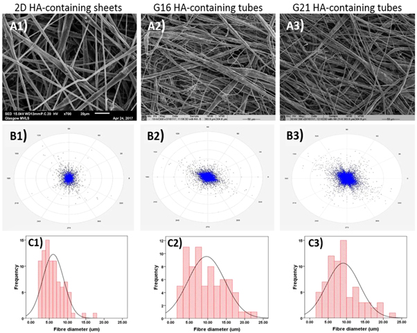
Figure 6. SEM micrographs of HA containing (A1) 2D sheets, (A2) G16 tubular scaffolds, and (A3) G21 tubular scaffolds (marker bars = 20 μm for A1 and 50 μm for (A2) and (A3). (B) The calculated fibre alignment pattern for HA containing (B1) 2D sheets, (B2) G16 tubular scaffolds, and (B3) G21 tubular scaffolds. (C1)–(C3) Shows the fibre diameter distribution of the HA containing 2D scaffolds, G16, and G21 tubular scaffolds, respectively.
Download figure:
Standard image High-resolution imageTable 2. Fibre diameters and porosities for Control and HA containing 2D and tubular scaffolds.
| Control | HA containing | |||
|---|---|---|---|---|
| Needle collector gauge size | Fibre diameter (μm) | Porosity (%) | Fibre diameter (μm) | Porosity (%) |
| 2D control samples | 4.42 ± 1.14 | 90.3 ± 2.9 | 6.06 ± 2.89 | 88.3 ± 3.4 |
| G16 (OD = 1.35 mm) Speed = 31.1 mm s−1 | 5.78 ± 1.52 | 85.6 ± 3.4 | 9.65 ± 5.01 | 88.2 ± 4.0 |
| G21 (OD = 0.67 mm) Speed = 15.4 mm s−1 | 5.84 ± 0.91 | 91.3 ± 3.5 | 9.08 ± 4.51 | 90.4 ± 2.4 |
3.2. Mechanical testing
The tensile properties for electrospun 20%PCL, 15%PLA with 20%HA scaffolds in addition to co-electrospun PCL-PLA and PCL-PLA/HA scaffolds as 2D sheets and 3D tubes at core:shell flow rate ratio of 3:3 are shown in table 3.
Table 3. Mechanical properties of 2D and 3D electrospun PCL-PLA and PCL-PLA/HA at 3:3 core:shell flow rate ratio along with PCL and PLA/HA single core scaffolds.
| Scaffold | Young's modulus (MPa) | UTS (MPa) | Elongation at break (%) |
|---|---|---|---|
| 2D single core PCL | 4.92 ± 0.77 | 0.837 ± 0.200 | 323.2 ± 119.1 |
| 2D single core PLA/HA | 59.54 ± 9.66 | 0.263 ± 0.055 | 13.1 ± 2.9 |
| 2D core–shell PCL-PLA | 41.23 ± 8.59 | 1.259 ± 0.396 | 102.6 ± 17.4 |
| 2D core–shell PCL-PLA/HA | 31.33 ± 5.04 | 0.680 ± 0.101 | 30.5 ± 4.4 |
| 3D core–shell PCL-PLA (G16) | 8.62 ± 2.19 | 0.621 ± 0.147 | 94.6 ± 15.1 |
| 3D core–shell PCL-PLA/HA (G16) | 5.12 ± 1.63 | 0.337 ± 0.082 | 29.9 ± 4.7 |
3.3. Biodegradation and bioactivity
Minimal differences were seen in water uptake and weight loss between the control and HA containing scaffolds in PBS, however, in SBF the variability in the results was substantially larger. The control scaffolds showed continuous weight loss during 12 weeks of SBF immersion while for HA containing scaffolds, the weight loss decreased noticeably at week 12 of immersion (figure 7(a)).
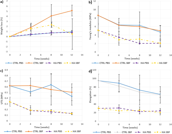
Figure 7. (a) Weight loss, (b) Young's moduli, (c) UTS and (d) elongation at failure of control and HA containing tubular scaffolds during 12 weeks of immersion in PBS or SBF.
Download figure:
Standard image High-resolution imageFigure 8 shows the morphologies of tubular scaffolds after 4, 8 and 12 weeks of immersion in either PBS or SBF. In both solutions, the samples maintained their shape and no fibre swelling was noticed, although all samples were dried prior to SEM. No apatite formation was observed on the fibres immersed in PBS (figures 8(a1)–(a3) and (c1)–(c3)) or control fibres in SBF (figures 8(b1)–(b3)). Most of HA containing fibres also preserved their structure during immersion in PBS (figures 8(c1)–(c3)). However, few broken fibres were observed, where the fibres narrowed, at week 8 (figure 8(c2)). In SBF, the HA containing scaffolds showed high levels of bioactivity with white layers of apatite already formed on the surface of the fibres after 4 weeks. The extent and thickness of the apatite layer grew with increasing immersion time (figures 8(d1)–(d3)).
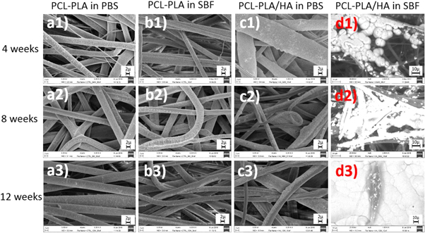
Figure 8. SEM images of coaxial control and HA containing tubular scaffolds after immersion in PBS or SBF for 4, 8, and 12 weeks, respectively (marker bars for (a1)–(c2) = 2 μm and for (d1)–(d2) = 10 μm)
Download figure:
Standard image High-resolution image3.4. EDX
Figures 9 and 10 show the EDX spectra of HA containing scaffolds along with element mapping before and after 12 weeks of immersion in SBF. The control samples showed carbon and oxygen only from the PCL and PLA. However, the presence of HA is seen on the surface of the HA containing fibres even before soaking, with calcium and phosphorous peaks present, but at a lower level than the carbon peak, and the calcium to phosphorous ratio being 1.68, very close to that of stoichiometric HA (1.67) (figure 9). After soaking (figure 10) deposited apatite can be seen along with small amounts of chlorine and magnesium from the SBF and a reduction in the calcium to phosphorous ratio.
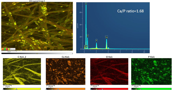
Figure 9. EDX spectrum and mapping of HA containing scaffolds before immersion showing the distribution of carbon (C), calcium (Ca), oxygen (O) and phosphorus (P).
Download figure:
Standard image High-resolution image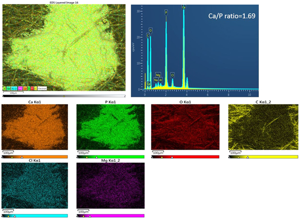
Figure 10. EDX spectrum and mapping of HA containing fibres after 12 weeks immersion in SBF showing the distribution of calcium (Ca), phosphorus (P), oxygen (O), carbon (C), chlorine (Cl) and magnesium (Mg).
Download figure:
Standard image High-resolution imageThe Young's moduli, ultimate tensile strength, elongation at failure for control and HA containing tubular scaffolds before and after 12 weeks immersion in PBS or SBF are shown in figures 7(b)–(d). Gradual decreases in all these properties can be seen, but they are all capable of load bearing even after 12 weeks soaking. Minimal differences between the effects of PBS or SBF can be seen.
3.5. BMP-2 release
The cumulative release of BMP-2 over 96 h for coaxial PCL-PLA (control) and PCL-PLA/HA scaffolds is shown in figure 11. Two regions are observed, the first 4 h showed a high release rate with a second linear phase of 0.0672% h−1 and 0.0728% h−1 for the control and HA containing scaffolds respectively. The BMP-2 release behaviour showed minimal differences between control and HA containing samples over 96 h.
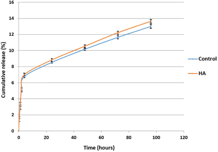
Figure 11. Cumulative release of BMP-2 from coaxial control and HA containing scaffolds.
Download figure:
Standard image High-resolution image3.6. Cell culture
Figures 12 and 13 show SEM images of MSC adhesion and interaction with control and HA containing coaxial scaffolds respectively at days 1, 7, 14 and 21 of culture. On both scaffolds, cell had spindal shaped or rounded morphologies and were mainly seen to interact with single fibres, aligned along the fibre length. After 7 d culture, MSCs were seen to be spread between fibres and anchored to fibres with numerous filopodal projections. Observed cell numbers increased with culture time and retained a spread morphology typical of MSCs in culture. With increased culture time more cells were observed to have migrated deeper into the scaffold through the inter-connected pore structure. Inclusion of HA did not appear to alter cell morphology or the ability of cells to invade the scaffolds, though the microporous structure of HA containing scaffolds resulted in cells producing more filopodal projections (e.g. figure 13(f)), is likely to enhance initial cell attachment.
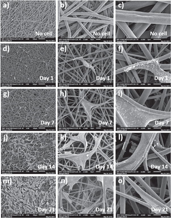
Figure 12. SEM images of coaxial control, that is without HA, scaffolds at different days and magnifications showing (a)–(c) fibres before cell culture and after (d)–(f) 1 d, (g)–(i) 7 d, (j)–(l) 14 d and (m)–(o) 21 d of MSCs culture (marker bars for (a), (d), (g), (j) and (m) = 100 μm, for (b), (e), (h), (k) and (n) = 10 μm and for (c), (f), (i), (l) and (o) = 5 μm).
Download figure:
Standard image High-resolution image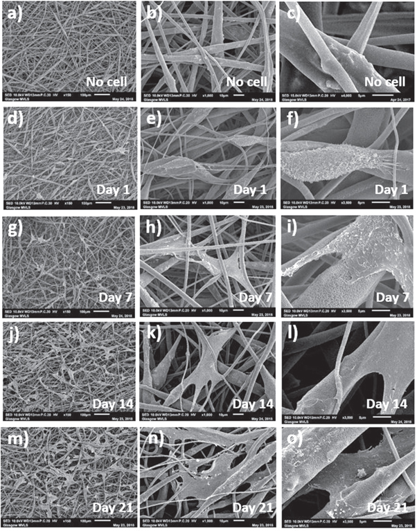
Figure 13. SEM images of coaxial HA containing scaffolds at different days and magnifications showing (a)–(c) fibres before cell culture and after (d)–(f) 1 d, (g)–(i) 7 d, (j)–(l) 14 d and (m)–(o) 21 d of MSCs culture (marker bars for (a), (d), (g), (j) and (m) = 100 μm, for (b), (e), (h), (k) and (n) = 10 μm and for (c), (f), (i), (l) and (o) = 5 μm)
Download figure:
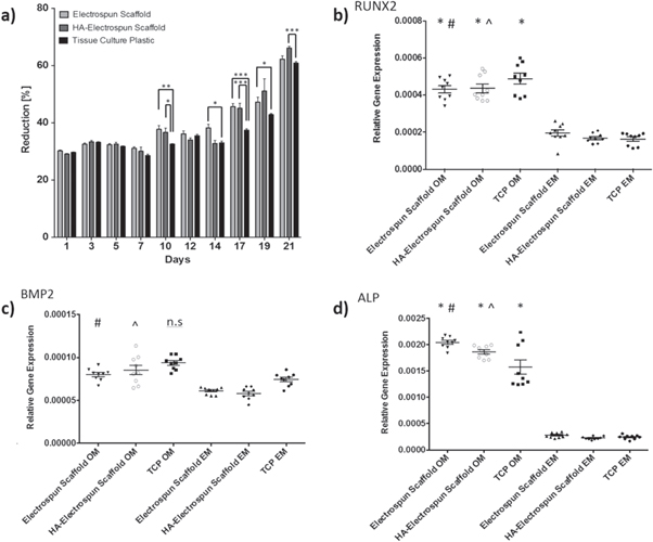
Standard image High-resolution imageMSCs could be seen to adhere, spread and grow on the fibres. Using Alamer blue metabolic assay to infer cell proliferation, it was seen that both HA-containing and control scaffolds supported MSC proliferation over 21 d in culture (figure 14(a)). Alamar blue reduction was significantly increased on electrospun scaffold cultures at various time points in comparison with tissue culture plastic controls, particularly at the later stages of culture (between 14 and 21 d), indicating sustained cell proliferation. No significant difference was observed when culturing on HA-containing or control electrospun scaffolds without HA. When taken with the SEM images, this indicates more growth area in the electrospun scaffolds and cell invasion into the scaffold, thereby reducing contact inhibition of cell proliferation.
Figure 14. (a) MSC proliferation assessed through Alamar Blue Assays. Mean Alamar Blue reduction ± SEM was assessed over 21 d to estimate cell proliferation (n = 3; *p < 0.05, **p < 0.01, ***p < 0.001), (b)–(d) show qRT-PCR analysis of osteogenic gene expression after 21 d culture in osteogenic or control conditions. Data shown represents means ± SEM (n = 3 independent triplicates (*p < 0.05 versus tissue culture plastic expansion media; #p < 0.05 versus electrospun scaffold expansion media; ^p < 0.05 versus HA-containing scaffold expansion media; n.s.- no significant difference versus tissue culture plastic TCP expansion media).
Download figure:
Standard image High-resolution image
qRT-PCR data indicated that scaffolds supported MSC osteogenic differentiation when stimulated with osteogenic media in culture, that is they are osteoconductive (figures 14(b)–(d)). Expression of RUNX2, a critical osteogenic transcription factor, was significantly increased in osteogenic cultures on scaffolds in comparison to expansion media controls (HA-containing scaffolds osteogenic versus TCP expansion media p = 0.0024; control scaffolds osteogenic versus TCP expansion media p = 0.0049; TCP osteogenic versus expansion p = 0.0002) indicating induction of osteogenic gene transcription. BMP-2, a growth factor important during osteogenesis, was significantly upregulated in osteogenic cultures in comparison to expansion media cultures on MSCs cultured on electrospun scaffolds (HA-containing scaffolds osteogenic versus expansion media p = 0.0029; control scaffolds osteogenic versus expansion media p = 0.0321; tissue culture plastic p = 0.157). Alkaline phosphatase is a marker of mature osteogenic differentiation and a critical enzyme in the mineralisation of new osteogenic tissue. The expression of alkaline phosphatase was also significantly upregulated in osteogenic cultures on electrospun scaffolds in comparison to expansion media controls (HA-containing scaffolds osteogenic versus tissue culture plastic expansion media p = 0.0091; control scaffolds osteogenic versus tissue culture plastic expansion media p = 0.0001; TCP osteogenic versus expansion p = 0.025).
4. Discussion
The relative flow rates of core and shell solutions affects the uniformity and stability of the core jet flow [8]. A range of studies have found that the core and shell layer dimensions can be tailored by keeping one flow rate constant while altering the other [9–11]. To optimise fibre morphology in this study, core and shell solutions were fed at 2:3 and 3:3 flow rate ratios. Both flow rates produced uniform and beadless fibres, however, the 3:3 flow rate ratio fibres exhibited more homogenous diameters than those made at 2:3 flow rate ratio. The viscosities of both solutions play a decisive role in controlling fibre diameter as well as the relative thicknesses [12]. Thus, polymer concentration, filler type and filler concentration can significantly alter fibre uniformity and control layers thicknesses.
The fibres surface exhibited nanoporous structure (figure 3(a)) resulting from solvent volatility. According to Bognitzki et al [13], surface pore formation occurs when using highly volatile solvents, as fast evaporation of a solvent gives rise to local phase separation where solvent-rich and solvent-poor regions are formed in the polymeric solution, the solvent-rich regions are transformed into pores during the evaporation process. Srinivasarao et al [14] suggested a different mechanism for the formation of surface pores on electrospun fibres known as 'breath figures'. These are imprints created by the heat loss resulting from the rapid evaporation of the solvent, thus significantly cooling the surface of the electrospinning jet as it travels to the collector. As the jet surface cools, moisture in the air condenses and grows as spherical droplets due to convection currents on the surface of the jet. Finally, the water droplets evaporate as the jet dries on the collector, leaving surface imprints in the form of pores. Thus, the formation of breath figures indicates the presence of humidity in the atmosphere in addition to the use of volatile solvents. A porous fibre surface has several advantages including increasing the surface area and providing more sites for drug loading and cell attachment (figures 13(f) and (i)) and can affect the roughness and wetting behaviour of the scaffolds [15, 16].
SEM images of fractured (3:3) coaxial fibres (figure 3(a)) did not show an exposed core layer as some studies suggest [17–19], however, it did show a few hollow fibres. TEM cross-sectional images show clearly the core and shell configuration and the surface porosity, but no mixing between the layers. Fibres of both scaffolds had non-uniform shell thickness and thus non-concentric cores which can be attributed to the whipping motion of the fibres during electrospinning. Some fibres also had discontinuous shell layers which might have resulted from needle blockage, while a few shell-only regions were observed. Reznik et al [20] recognised that a core–shell droplet at the tip of the needle does not necessarily result in core solution entrainment and thus not all fibres possess core–shell structure. The shell layer thickness variability increased in the HA containing fibres due to HA protuberances and ranged from ∼0.7 to 2.3 μm for fibres at 2:3 flow rate ratio versus ∼0.2 to 1.8 μm for fibres at 3:3 flow rate ratio. Therefore, only partial encapsulation of the HA particles occurred with some HA exposed on the surface. Finally, control and HA containing coaxial fibres with FTIC labelled PLA/HA shell phase and rhodamine B labelled PCL core phase were used to visualise the incorporation of the core and shell phases in individual fibres. Similar results were obtained by Ji et al [21] and Vysloužilová et al [22], but without distinct boundaries between the layers. However, Blackstone et al [23] in confocal micrographs for their core and shell PCL-gelatin scaffolds showed clear boundaries between the layers at various core:shell flow rate ratios. For the HA containing scaffolds, HA particles in the shell layer were surprisingly observed on the red channel which should be solely the core phase. It is possible that they appeared on the red channel along with core component due to internal protuberances mixed with the red tagged PCL, while HA that protrudes outside the fibres appears more intensely in the green channel, another option is that the HA absorbed some of the rhodamine B.
Tubular scaffolds were produced using a rotating needle collector. The resultant electrospun tubes on a G16 needle (figure 4(b)) had an external diameter of around 2.86 mm and wall thickness of around 1.65 mm, while with the G21 needle collector these were ∼1.95 and 1.35 mm, respectively (figure 4(c)) with no significant differences between the scaffolds. SEM images of control scaffolds showed uniform, bead-free fibres with average diameters slightly higher than those for the 2D control sheets. Jungst et al [5] examined the effect of collector diameter and rotational speed on the diameter of electrospun PCL fibres to give surface velocities between 62.8 and 628.3 mm min−1. They found that varying the diameter and tangential speed of the collector did not affect the fibre diameter significantly. While in this study using the rotating collector did not affect fibre diameter, electrospun tubes exhibited increased circumferential alignment of the fibres compared to the 2D fibrous sheets (figures 5 and 6). Both control and HA containing samples immersed in PBS exhibited slow degradation (figure 7) with a weight loss rate of 0.3%–0.4% every 4 weeks. These results are expected since PCL and PLA are known to have very slow degradation rates even in their nanofibrous form, while the inclusion of HA particles has also been shown to slow the degradation of PLA [e.g. 24]. On the other hand, control samples immersed in SBF have shown significantly faster weight loss compared to those in PBS, although the weight loss remained generally low during the 12 weeks of immersion with a total weight loss of 5.14% ± 1.09%. During the first 4 weeks of immersion, the HA containing samples exhibited similar degradation behaviour as the control samples. By week 12 of SBF immersion, the HA containing samples exhibited significantly reduced weight loss down to 0.50% ± 3.02%. Since the HA did not affect significantly the weight loss in PBS, the reduction in weight loss rate can thus be attributed to apatite formation on the fibre surfaces.
SEM was used to observe the morphological changes, as expected, no noticeable changes were seen in the control fibres after immersion in either solution over 12 weeks (figure 8). In addition, no apatite-like materials were precipitated on the surface of the SBF immersed control fibres at any time, confirming that these fibres did not induce bone mineral-like growth. HA containing fibres incubated in PBS also preserved their microstructure during the immersion period with no apatite formed on the fibre surfaces with only few broken fibres found at week 12 of immersion (figure 7(c)). However, for HA containing samples immersed in SBF, apatite nucleation from the exposed HA crystals on the fibres surface was observed after week 4 of immersion and apatite was deposited (figure 8(d)). The thickness and area of the apatite layer formed on the coaxial HA containing fibres increased with increasing soaking time [25, 26], and after soaking for 12 weeks in SBF, large areas of the scaffolds were covered by a thick layer of apatite (figure 8(d)) with some fibres cracked opened with HA particles exposed, offering potential areas for apatite nucleation.
EDX spectra of control samples were mainly the carbon and oxygen peaks attributed to both polymers. However, there were no calcium or phosphate peaks at any time after SBF immersion confirming SEM and weight loss results that the control scaffolds were not bone bioactive. EDX spectra of HA containing samples before immersion confirmed the presence of HA within the fibres. After immersion in SBF, EDX mapping of elements composition over the precipitated layer showed that it was mainly composed of calcium and phosphorus atoms related to mineral deposition and that the intensity of these peaks increased with soaking time.
For 2D coaxial electrospun scaffolds the mechanical properties of the core and shell structured mats were between those of the core and shell monolithic fibres (table 3). Coaxial PCL-PLA/HA scaffolds had significant increases in tensile strength and elongation compared with PLA/HA alone, while the stiffness of the coaxial scaffolds decreased significantly. The reduction in Young's modulus for coaxial scaffolds could have resulted from the non-uniform distribution of core solution along the fibres due to HA particles. Control coaxial scaffolds without HA exhibited significantly higher ductility, strength and stiffness than HA containing scaffolds. Both tubular scaffolds showed a significant reduction in their tensile strength and stiffness compared to the 2D coaxial sheets while the elongation to failure was not affected significantly. Since tubular scaffolds fibres were more aligned than the 2D sheets, the reduction in tensile properties could have resulted from the anisotropy with the loading applied perpendicular to the fibre direction [27]. Randomly distributed fibres will lead to isotropic properties while aligned fibres will produce anisotropy with the highest values obtained in the direction of the fibre alignment. Prabhakaran et al [28] evaluated the tensile properties of their circumferentially aligned PHBV/collagen scaffolds in both axial and circumferential directions and found that the aligned nanofibers exhibited anisotropic behaviour, with the tensile strength and Young's modulus in the circumferential direction significantly higher than those axially.
The tensile properties of tubular control and HA-containing scaffolds were also evaluated after soaking (figure 7). In general, minimal changes in the structural integrity were seen even after 12 weeks. Control samples showed a gradual reduction in their tensile properties over the incubation period, however, they generally preserved tensile strength and stiffness, while the ductility started to reduce significantly in SBF at week 8. In contrast, HA-containing samples maintained their ductility, while their strength and stiffness were reduced significantly during immersion in both PBS and SBF. However, the ductility was mainly preserved due to the PCL core, known to degrade slowly. Finally, no statistically significant differences were found between the mechanical properties of scaffolds immersed in PBS and those in SBF for both control and HA-containing samples.
The release profile of BMP-2 in vitro was determined using ELISA (figure 11). A burst release of about 8.8% of the BMP-2 was observed in both scaffolds during the first 24 h. The release rate subsequently decreased to become more uniform with about 1.2%–1.6% released every 24 h, and approximately 13.0% and 13.6% of the total BMP-2 was released from the control and HA-containing scaffolds, respectively, after 4 d. Talal et al [29] measured the absorption and release of fetal calf serum and bovine serum albumin from trilayer PLA and HA-PLA composite membranes reinforced with PLA fibres. They found that that HA-containing composites exhibited significantly more total protein absorption and release compared to those without HA and that more than 90% of the protein was released after 96 h. However, in this study, no significant difference were noticed in the protein release behaviour, in fact, both types of scaffolds had the same release kinetics and retained more than 86% of BMP-2 after 96 h. While these findings suggest that the coaxial scaffolds produced can be used as an efficient carrier for the sustained release of BMP-2, which can ultimately effect osteogenic differentiation and bone regeneration, the release behaviour should be measured over longer time periods in order to define the exact release mechanism and determine the influence of including HA in the shell layer.
The interaction between cells and their environment plays a crucial role in determining cell function. This includes ECM molecular composition, architecture and mechanical properties (e.g. stiffness), all of which have been shown to influence MSC behaviour [30]. A major advantage of electrospun fibres is that they favour cell attachment due to their high surface area which helps absorb proteins and promote binding sites [31, 32]. Cell adhesion is a dynamic process that results from specific interactions between cell surface molecules (in particular integrins) and their appropriate attachment sequences in ECM molecules (e.g. the RGD sequence) [33]. Cell adhesion on control and HA-containing coaxial scaffolds and the morphology of the adhered cells were observed using SEM (figures 12 and 13). MSCs adhered to both scaffolds and were initially observed to have small, spindle-shaped or rounded morphologies, aligning with single fibres (figures 12(e), (l) and (o)). Clear filopodial projections were seen to anchor the cells to the fibres. With increasing culture time, the MSCs adopted a spread, large morphology with F-actin staining demonstrating the formation of stress-fibres within the cells. This change is likely due to the establishment of specific integrin attachment sites following deposition and ECM produced by the cells themselves. The architecture of these electrospun scaffolds supports this deposition and facilitates cell migration into the scaffolds through interconnected pores. Interestingly, the presence of surface nanopores on fibres facilitated cell adhesion, (figures 13(f) and (i)) where cell filopodia were seen to interact directly with these nanopores. Incorporation of HA did not affect significantly cell attachment and spreading. However, cell spreading was slightly lower in HA-containing scaffolds at day 21 which might be attributed to the increased fibre diameter and non-uniformity compared to control scaffolds [34, 35]. Fibre diameter has previously been linked to both proliferation and cell morphology and is probably involved in stem cell differentiation [36]. Similar levels of proliferation were observed in HA-containing and control scaffolds. Previous work would suggest this may be due to the relatively large size of the fibres produced here (∼10 μm) effectively resulting in similar cell adhesion formation between both groups. The presence of HA did not influence cell proliferation in culture. At late stages of culture (>14 d) cell proliferation was observed to be greater on electrospun scaffolds than tissue culture plastic controls. This, along with SEM images showing cell invasion into electrospun scaffolds, suggests that the cells have a greater growing surface and perceive the scaffolds as three-dimensional fibre networks rather than two-dimensional planar substrates. Thus, while not shown to be specifically osteoinductive, the materials were seen to be osteoconductive, allowing differentiation of the MSCs when conditions were right, that is an osteogenic media was supplied.
5. Conclusions
2D and 3D PCL-PLA/HA scaffolds with core and shell structured fibres were successfully produced using coaxial electrospinning. The uniformity of the produced fibres depended on the flow rate ratio between the core and shell solutions, with higher fibre uniformity achieved at a flow rate ratio of 3:3.
TEM of HA containing scaffolds showed that increasing the core flow rate also forced HA particles to protrude out of the fibre surface which could enhance scaffold bioactivity.
Electrospinning on rotating needle collector did not affect fibre diameter for either control or HA containing samples. However, it increased the fibre alignment around the collector and increased fibre non-uniformity in the HA-containing scaffolds.
Tubular scaffolds with and without HA have shown slow degradation profiles in PBS and SBF. However, HA-containing tubes have exhibited high level of bioactivity in SBF by forming thick layers of apatite precipitation on the fibres surface while no apatite was formed on control fibres even after 12 weeks of SBF immersion.
Electrospinning of 2D core and shell PCL-PLA/HA fibres has significantly enhanced the tensile strength and elongation at break compared to PLA/HA fibres produced by single electrospinning, while the toughness of the scaffolds was significantly reduced.
By increasing fibre alignment in 3D scaffolds, scaffolds showed anisotropic mechanical behaviour with reduced mechanical properties when tested across fibre orientation. Both tubular scaffolds have shown gradual reduction in their tensile properties after 12 weeks of immersion. The reduction in tensile strength and stiffness were more significant in HA-containing scaffolds compared to control scaffolds. However, the two types of scaffolds retained most of their ductility during immersion.
Control and HA containing coaxial fibres electrospun at 3:3 core:shell flow rate exhibited slow and sustained release of BMP-2 over 96 h with only small variations between the two scaffold types. These scaffolds also allowed MSC attachment, spreading and proliferation and support osteogenic differentiation of MSCs under osteogenic culture conditions.
While not shown to be osteoinductive, the materials were osteoconductive, allowing differentiation of the MSCs when an osteogenic media was supplied.
Acknowledgments
The work was supported by an Iraqi Government Scholarship Grant (number S1648). Additional funding for testing was provided by EPSRC UK (grant numbers EP/N013905/1 and EP/P001114/1). The authors would also like to thank Dr Annie Zhe Cheng, Mrs Margaret Mullin, Dr Jafar Alsayednoor and Mr John Davidson for their help with protein release experiment, SEM and TEM testing, image analysis, and mechanical testing, respectively.