


Abstract
Simulations exploring neutral beam operation in Wendelstein 7-X (W7-X) at reduced magnetic field are performed using a newly implemented gyro orbit model in the BEAMS3D code. Operation at field strengths below the nominal 2.5 T are seen as a path to explore both high beta plasmas and as a means to access magnetic configurations not possible at 2.5 T. As the field strength becomes smaller, the gyro radius for 55 keV fast protons grows from  at 2.5 T to
  at 0.75 T in a device with minor radius
  bringing into question the applicability of the gyro center approximation. To address this a gyro orbit model was implemented in the BEAMS3D code. Agreement is found between the gyro center and gyro orbit models in a circular cross section tokamak equilibrium at high field. A set of W7-X equilibria are assessed with fixed density and temperature profiles but decreasing magnetic field strength (increasing plasma beta). Neutral beam deposition is found to be mostly unaffected with changes in the core of the plasma associated with the Shafranov-shift. In general good agreement is found between gyro orbit and gyro center simulations at 2.5 T. Both models indicate increasing losses with decreasing magnetic field strength with the gyro orbit losses being higher at all field strengths. Gyro orbit simulations to the first wall of W7-X show a change in loss pattern with decreasing magnetic field strength. A preliminary assessment of losses to fast ion loss detectors are made.
Export citation and abstract BibTeX RIS

Original content from this work may be used under the terms of the Creative Commons Attribution 4.0 license. Any further distribution of this work must maintain attribution to the author(s) and the title of the work, journal citation and DOI.
1. Introduction
The effect of lowered toroidal magnetic field strength on Neutral Beam Injected (NBI) fast ions in Wendelstein 7-X (W7-X) is assessed through gyro orbit simulations performed with the BEAMS3D code [1]. Lowered magnetic field strength is one method being considered as a means to achieve high plasma beta (β) in W7-X. Lower magnetic field implies lower electromagnetic loads on the superconducting coils, opening the space of magnetic configurations which can be realized in W7-X. As the magnetic field is lowered the gyro-radii of particles grow and the gyro center approximation, considered valid for 55 keV NBI ions at 2.5 T, begins to break down. In general, we expect confinement to degrade with field strength (irrespective of the orbit model) due to interplay between the curvature and  drifts. To address this the BEAMS3D code has recently been modified to solve both the gyro center equation of motion and evolve particle positions based on a direct calculation of the Lorentz force (gyro orbit). This work compares simulations of the NBI system of W7-X using both a gyro center and gyro orbit model to explore the effect of lowering magnetic field strength (and subsequently increasing plasma beta) on energetic particles.
Lowering the magnetic field in W7-X is envisioned as a path toward achieving high plasma beta scenarios in W7-X without the necessity of substantial heating upgrades. High plasma beta operation is key to demonstration of the optimization of W7-X. To date plasmas betas of only around  (volume averaged) have been achieved due to limited heating power and ion temperature clamping [2]. Additionally, lower magnetic field places lower electromagnetic loads on the superconducting coils. This in turn allows configurations deemed unsafe due to excessive coil stresses to be realized. While X2 mode electron cyclotron resonance heated (ECRH) plasma start-up at 2.52 T is reliably achieved, attempts at X3 startup at 1.7 T have yet to be successful. NBI-startup in W7-X has been shown to be not possible due to beam dump thermal limits of roughly 500 ms unattenuated shine through [3]. With the installation of an Ion Cyclotron Resonance Heating (ICRH) antenna in W7-X, a non-resonant ICRH startup scenario should be possible [4, 5]. It is envisioned that such a plasma can be overtaken by NBI allowing achievement finite beta plasmas without the need for an ECRH resonance in the plasma. The achievement of higher plasma beta of course assumes that a sufficient tradeoff between heating power and confinement can be maintained, such an analysis is beyond the scope of this work.
In reducing the magnetic field strength in W7-X, the gyro-radii of all particles becomes larger. Of particular interest is the effect on NBI generated fast ions, as NBI is assumed to be the primary heating source in this work [6]. Of course ECRH could be used in X3 mode at 1.7 T, providing a path to steady-state low field operation. To date most analysis of the W7-X NBI heating has been done with a gyro center model. Gyro orbit (or full-orbit) simulations have only been invoked in the edge for particle loss studies [7–9] and in the core for Triton burn-up studies [10]. In this work a W7-X equilibria with fixed kinetic profiles and varying magnetic field strength (from 0.75 to 2.5 T) are assessed both with gyro center and gyro orbit models.
To perform such simulations, the BEAMS3D code has been modified to include the possibility of pushing particles with the Lorentz force. The code now allows for gyro orbit equations of motion to be followed once a user defined radial limit is passed by a gyro center particle. Setting the limit to zero allows gyro orbit simulations to be followed from the point of neutral beam particle ionization. The equations are still solved using an Adams method [11]. While volume preserving methods (such as the Boris algorithm) have been shown to conserve both magnetic moment and energy over long time periods [12], it has been found that adaptive methods such as Adam's are sufficient for works such as these. This is attributed to the notion that collisions are a significant contributor to NBI fast ion dynamics in W7-X. Additionally, the conservation of magnetic moment comes into questions for systems where the magnetic field changes strongly over the gyro-period of the particle, as has been found for spherical tokamaks [13].
This work assesses the effect of lowered magnetic field strength on fast ion confinement in W7-X through full orbit simulations of NBI fast ions. In the next section (section 2), the model employed and cases studied are presented. Demonstrations of the BEAMS3D code's ability to capture orbit dynamics are also shown. In section 3, simulations results scanning magnetic field strength (and in parallel plasma beta) are presented. This includes comparison between gyro center and gyro orbit simulations. In section 4, the results are discussed along with paths for future work.
2. Methods
Simulations of NBI injection and confinement for a range of magnetic field strengths are performed for the W7-X standard magnetic configuration. For this scan VMEC equilibria are computed with fixed kinetic profiles [14], self-consistent pressure profiles, and neoclassical bootstrap currents. As confinement may degrade with field strength, a rather low performance set of profiles has been chosen. Simulations of neutral beam injection are performed with all eight sources of the NBI system. The results are easily downsampled to the planned four installed sources where appropriate. Slowing down simulations to the equilibrium last closed flux surface are performed with the BEAMS3D code. Here both gyro center following and gyro orbit following simulations are performed to highlight the differences in models as field strength is lowered. Finally, collisionless gyro orbit simulations are performed from the VMEC boundary to the first wall of W7-X.
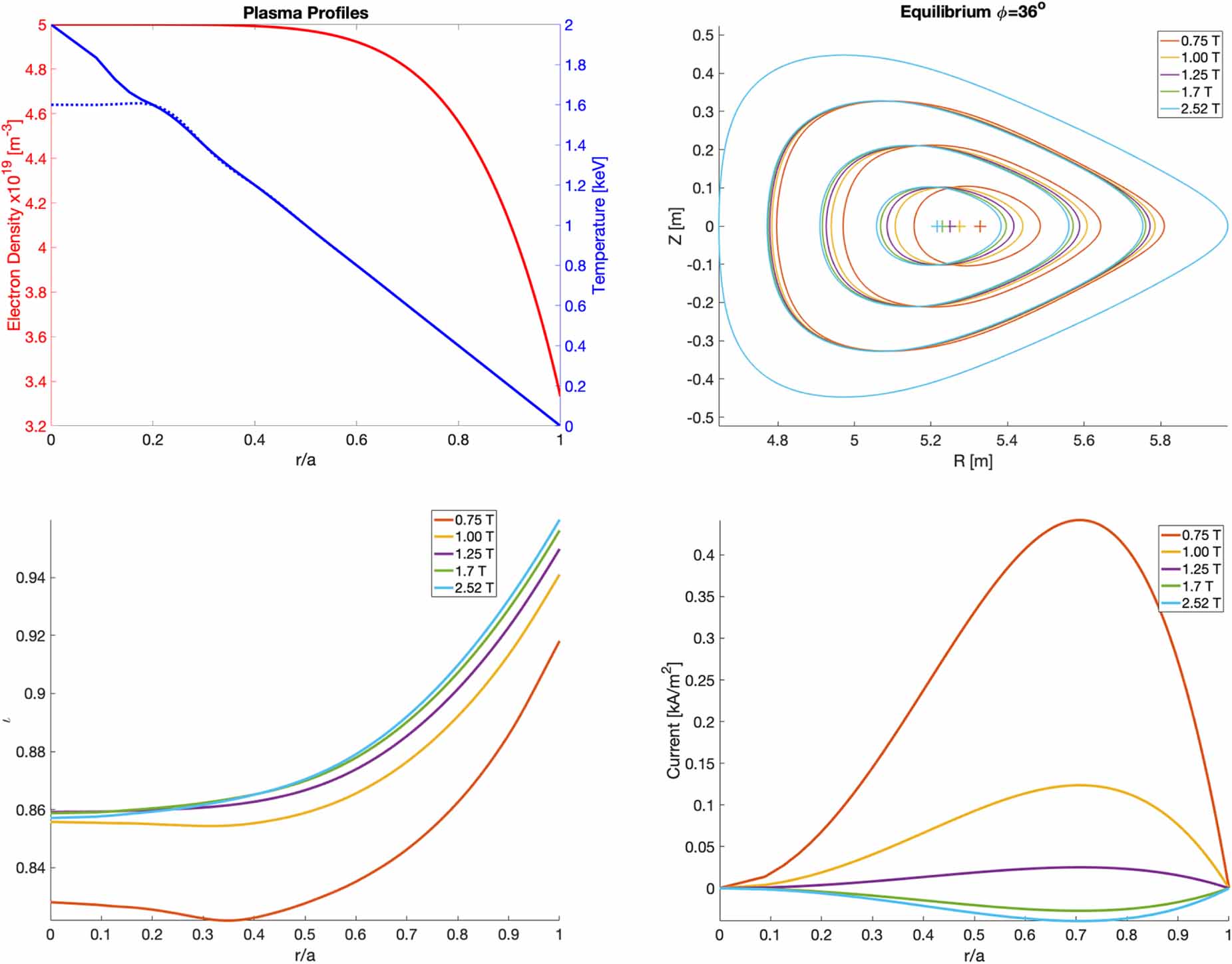
The simulations begin with carefully constructed VMEC three dimensional equilibria for the W7-X standard magnetic configuration. The field strength, as measured on-axis in the bean shaped cross section, is varied from 2.52 T to 0.75 T. This is done by changing the normalization factor ( ) on the total field strength. A 0.5 T run was also performed but the equilibrium indicated strong variation in the flux surfaces and a rotational transform (
 ) which crossed many rational surfaces, thus it is excluded from this analysis. Temperature and density profiles are chosen based on experience with W7-X plasmas (figure 1). Here
  is the normalized radial coordinate and
  is the normalized toroidal flux. These profiles sit at a rather modest point in the configuration space and should be achievable even if thermal confinement drops significantly. Neoclassical estimates for the bootstrap current and radial electric field are calculated based on the magnetic configuration, magnetic field strength, and plasma profiles [15]. This then allows for a self-consistent equilibria to computed and used for simulations with the BEAMS3D code. It should be noted that a
  modulation in the magnetic field exists in the toroidal direction at mid radius in the standard configuration. For comparison, a
  variation in the field strength exists at the φ = 0 (bean shaped) cross section, while a
  variation in field strength exists at the
  (triangular) cross section.

Figure 1. Equilibrium quantities for the magnetic field strength scan. Plasma profiles (upper left) are chosen well within the achievable limits of W7-X. Flux surface at the half field period (upper right) show a moderate Shafranov shift. Only the 0.75 T case approaches the  rational surface. Toroidal current profiles (lower right) are chosen with a simple form while matched to the neoclassical total toroidal current.
Download figure:
Standard image High-resolution imageNeutral beam injection simulations are performed with the BEAMS3D code. In these simulations all eight sources of the NBI system are considered, four per beam box. As of this writing only four are installed, two complimentary sources in each of the two beam boxes. A beamlet model is used to model the injector geometry and a detailed scraper, port and wall model is used for the neutral beam deposition run of the code [16]. Neutral beam deposition and slowing down are broken into two runs to simplify the analysis and workflow. Algorithmically the code assumes mono-energetic beams. Simulation of the three energies produced by hydrogen NBI are performed using three identical beams with different beam energies and power. Such information is tracked for each particle in the simulations allowing for one to break any simulations down into a subset of beams or beam energies. Each energy of each beam is initialized with  markers with weights calculated as
  where P is the beam power, E the beam energy, and k an index over mono-energetic beam (in this case 24 mono-energetic beams for 8 hydrogen sources).
The Suzuki model for beam ionization is used in these simulations. Ionization cross sections are calculated for each marker across the plasma and used to determine the ionization position of the neutral. Once a neutral particle is ionized the ionization position is recorded. The gyro center position is then calculated from the background magnetic field and neutral velocity. For gyro orbit simulations the marker ionization position is used along with the neutral velocity vector. The neutral beam deposition simulations provide the initial conditions for the slowing down simulations.
Simulations of energetic particle slowing down are performed with both the well documented gyro center version of the code and a newly developed gyro orbit model. In both cases particles are pushed in cylindrical coordinates ( ). The gyro center equations of motion are:
where  ,
,  is the magnetic moment,
  is the electric field, and
  is the component of velocity parallel to
  . These equations are solved using an Adam's method with functional iteration [11]. Viscous slowing down and pitch angle scattering operators are applied between ordinary differential equation (ODE) solve time steps. For a more detailed discussion we point the interested reader to the published works [9].
A global user defined parameter determines the radial point at which the code will switch from gyro center to gyro orbit models. For the gyro orbit simulations performed in this work the value was set to zero. Any marker whose radial position exceeds this value is then stepped from gyro center to particle position using a random gyro-phase. It should be noted that when said radial parameter is set to zero the neutral ionization point is used and no conversion from gyro center to gyro orbit is needed. The gyro orbit equations of motion are:


where one can easily recognize the Lorentz force on the right hand side of the second equation (see appendix
The collisional operators in the gyro orbit model are essentially the same as that in the gyro center model. The main difference is that the plasma magnetic field, temperature, and density are not calculated at the gyro center position, but rather at the particle position. The operator is evaluated at time steps which are 1/8th the initial particle gyro frequency. For 55 keV protons in W7-X this tends to be in the nanosecond range. Markers are considered thermalized when their thermal velocity is equal to or less than 1.5 times the background thermal velocity.
Verification of our gyro orbit model is provide by examining banana orbits in a large aspect ratio circular cross section tokamak equilibrium. Marker energy and position is held fixed while the pitch angle is varied to generate banana orbits of different widths. Figure 2 shows the scaling of banana orbits for such an equilibrium for both the gyro center and gyro orbit simulations along with an example comparison of the detailed orbits. Smaller banana widths show good agreement between the two models while predicting a smaller width than analytic theory. Agreement worsens as the banana widths grow wider with the gyro center model trending to the analytic limit. Still the banana widths agree within the uncertainty associated with the finite orbit width of the gyro orbit simulations. While clearly not exhaustive, this simple test shows the code is behaving as expected in an analytic limit.

Figure 2. Trapped particle orbits in a circular cross section tokamak equilibrium as calculated by the BEAMS3D code. On the left a stereotypical gyro center (red) and gyro orbit (blue) marker trajectory are depicted, the dashed line indicates the mid-radius of the equilibrium. On the right we show the scaling of banana orbit widths with pitch angle. Here the dashed line indicates perfect agreement between analytic and measured widths. Error bars for gyro orbits indicate the effect of gyro radius width on the width of the simulated orbit.
Download figure:
Standard image High-resolution image3. Results
Simulations with the BEAMS3D code of the W7-X standard configuration for multiple values of toroidal field with fixed pressure profile were conducted (table 1). Neutral beam deposition simulations show little variation with plasma beta. This is attributed to the simulations having identical plasma profiles. Slowing down simulations for both gyro center and gyro orbit models show a general degradation in neutral beam generated fast ion confinement with decreasing magnetic field strength. This is consistent with our general understanding of particle confinement. Agreement between gyro center and gyro orbit simulations degrades with decreasing field strength. In general the gyro orbit simulations show poorer confinement than that of gyro center simulations.
Table 1. Overview of BEAMS3D simulations results for both the gyro center and gyro orbit simulations. The 8 source column takes into account all planned NBI sources while the 4 source column downsamples to sources 3, 4, 7 and 8 (as installed at the time of writing). Percentages are calculated based on total power. Average shine-through in all cases was 21% for 8 sources and 23% for 4 sources. rg is the Larmor (gyro) radius.
| Toroidal field (T) | rg (cm) |
 (Wb) (Wb) |

| Gyro center loss (%) | Gyro orbit loss (%) | ||
|---|---|---|---|---|---|---|---|
| 8 Sources | 4 Sources | 8 Sources | 4 Sources | ||||
| 0.75 | 4.5 | 0.44 | 0.5469 | 28 | 28 | 54 | 52 |
| 1.00 | 3.4 | 0.98 | 0.7292 | 18 | 18 | 37 | 36 |
| 1.25 | 2.7 | 1.82 | 0.9115 | 13 | 12 | 28 | 26 |
| 1.70 | 2.0 | 2.85 | 1.2396 | 8 | 8 | 18 | 17 |
| 2.52 | 1.3 | 5.11 | 1.8375 | 4 | 4 | 11 | 10 |
Simulations of neutral beam deposition show little dependence on toroidal field. Figure 3 shows the neutral beam deposition profile as a function of the major radius and radial coordinate. Little difference is present when viewed in the major radius coordinate. At these plasma parameters shine-through is still finite so the birth profile is an integral effect, spanning a large part of the plasma cross-section. In the radial coordinate ( ) we see a strong difference in birth profile due to
  Shafranov shift at 0.75 T and increasing flux surface volume with increasing radial coordinate. It should be noted that the gyro orbit model takes the ionization point as the initial condition for slowing down simulations while the gyro center model steps the particle to the gyro center based on a random gyro phase and local magnetic field strength. Differences between these initial conditions are subtle at 2.52 T given the Monte–Carlo nature of the code. In general we find an increase in particle births in the core of the plasma and small decrease in births toward the mid-radius and edge as field strength is decreased.
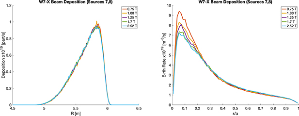
Figure 3. Neutral beam birth profile in major radius (left) and birth rate in radial coordinate (right). Totals are shown for sources 7 and 8 (source 3 and 4 are identical but fire in the opposite toroidal direction).
Download figure:
Standard image High-resolution imageOrbit simulations with pitch angle scattering and collisions show similar time histories of particle confinement for both gyro center and gyro orbit simulations (figure 4). In general, both models show a degradation of confinement with decreasing field strength. Power loss fractions are consistently higher for gyro orbit simulations with nearly a factor of two more power lost. Particle losses follow a similar trend although the difference in losses in much closer between the two models. This confirms that prompt losses, particles which leave the plasma before losing a significant amount of their energy, play a significant role in loss of fast ion power. In general, the time evolution of losses is not significantly different between the two models. Thermalization of particles becomes significant around 1 ms into the simulation. It should be noted that the VMEC boundary is used to indicate if a marker is lost, and no finite Larmor radius corrections are applied in the case of gyro center wall collisions.
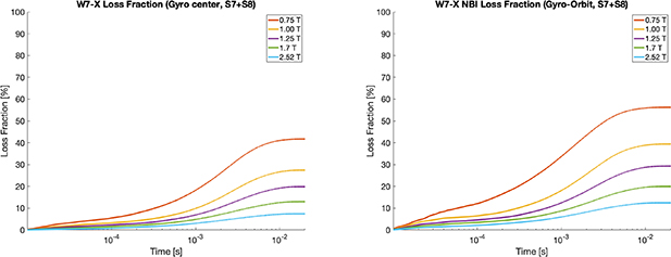
Figure 4. Fast ion particle loss fractions for gyro center (left) and gyro orbit (right) simulations. Particle loss fractions are plotted for sources 7 and 8 combined. Percentage based on total number of particles born in plasma. The VMEC boundary is used for determining when a marker is lost.
Download figure:
Standard image High-resolution imageThe fast ion density is consistent with the loss fraction, showing a decrease in fast ion density with decreasing magnetic field strength. Gyro orbit simulations show a lower fast ion density in the core, while values outside mid-radius show little difference between models. Additionally, gyro orbit simulations show a broadening of the core fast ion density profiles as the field strength is decreased. This behavior can be attributed to the increasing gyro radius of the particles, resulting in a given particle spanning a larger radial width. This is further confirmed by peaking present in the gyro center 0.75 T run.
The reduction in fast ion density correlates with a reduction in neutral beam heating as well (table 2). Considering gyro center orbits for source 7 and 8, 840 kW of power goes to the ions while 1150 kW of power goes to the electrons at 2.52 T. At 0.75 T these numbers drop to 540 kW and 900 kW respectively. In the gyro orbit model, we find a reduction of around 100 kW as compared to the gyro center model at 2.52 T. However, at 0.75 T the gyro center model predicts only 360 kW of heating to the ions and 520 kW to the electrons. It should be noted that while the ion heating remains core peaked in all cases, the electron heating becomes off axis at 0.75 T. The 1.7 T field strength simulations show only a  decrease in core power density over the 2.52 T cases. This is important as such a field strength is seen as a key operating point for W7-X given the presence of an X3 resonance for electron-cyclotron resonance heating.
Table 2. Overview of plasma heating and current drive for the gyro center (GC) and gyro orbit (GO) models. For heating all 8 neutral beam sources are considered. Current drive considers source 7 and 8 only.
| Toroidal field (T) |

| Electron heating (kW) | Ion heating (kW) | Current drive (kA) | |||
|---|---|---|---|---|---|---|---|
| GC | GO | GC | GO | GC | GO | ||
| 0.75 | 5.11 | 3630 | 2120 | 2360 | 1620 | 6.68 | 3.24 |
| 1.00 | 2.85 | 4100 | 2970 | 2820 | 2280 | 7.61 | 4.29 |
| 1.25 | 1.82 | 4340 | 3430 | 3070 | 2640 | 7.82 | 4.58 |
| 1.70 | 0.98 | 4520 | 3910 | 3280 | 3000 | 7.92 | 4.66 |
| 2.52 | 0.44 | 4670 | 4260 | 3460 | 3270 | 7.97 | 4.71 |
The neutral beam current drive shows a significant difference between gyro center and gyro orbit models (table 2). Both models show only a weak dependence on magnetic field strength, with only the 0.75 T case showing any significant decrease in current drive. In order to convert the fast ion current into a neutral beam current drive a correction to account for the trapped electrons is applied [18, 19]. We note that more sophisticated corrections to the current drive should be used when validating models of current drive [20, 21]. The difference between gyro center and gyro orbit models is nearly a factor of 2. The current density in all models shows little dependence on field strength outside of the  surface. In general, the peak current density (around
  ) decreases with field strength in a similar fashion to the total current. As the current is attributed to passing particles, the much more gradual decrease in neutral beam current drive suggests that the reduction in fast ion population seen in figure 5 can be attributed to a reduction in trapped particles with reducing field strength.

Figure 5. Fast ion radial distribution functions for gyro center (left) and gyro orbit (right) simulations showing decreasing confinement with decreasing magnetic field strength. Plots are for sources 7 and 8 combined.
Download figure:
Standard image High-resolution imageGyro orbit simulations allow for an assessment of fast ion loads to the first wall of W7-X, by following gyro orbit particles from the equilibrium boundary to the first wall collisionlessly. Figure 6 depicts a synthetic view from the AEF21 immersion tube based infrared camera. At lower field strengths loads have moved from the high heat flux divertor toward the baffle regions. In particular, the baffle region around the complimentary immersion tube port is loaded. The baffle and heat shield tiles in the high iota region of the divertor (right side of images) are also more significantly loaded at this low field level of 0.75 T. Such a change in loading can be attributed to both an increase in gyro-radius with decreasing magnetic field and decreasing overall confinement. An up-down asymmetry persists across all field strengths suggesting that additional armoring can be limited if a specific field direction is chosen for future full power NBI operation. For the wall load analysis we consider all eight planned NBI sources.

Figure 6. Wall loads as viewed from one of the divertor viewing infrared cameras systems on W7-X at 0.75 T (left) and 2.52 T (right). We see loads have moved from the main divertor region toward the baffles. Loads considered from all eight planned neutral beam sources.
Download figure:
Standard image High-resolution imageIn figure 7 the general change in wall distributions can be better seen. The poloidal variation in particle loss shows the up–down asymmetric nature of the loads. The strong peaks at the top and bottom locations are associated with the main divertor target and the smaller peak is associated with the vertical target. As field strength is reduced the divertor losses decrease and losses to the more outboard locations increase. These losses are associated with increase baffle and heat-shield losses as opposed to losses to the steel panels. The toroidal variation of losses at 2.52 T show peaked structures which are associated with the divertor, with five strong peaks and five less dominant peaks. The toroidally offset nature of the main divertor sections and up-down asymmetric losses due to fast ions gives rise to this structure. As field strength reduces we find in general a decrease in divertor losses with an increase in losses to regions between divertor modules. This change come from increased heat-shield losses near the high iota sections of the divertor.
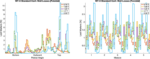
Figure 7. Histogram of marker losses in the poloidal (left) and toroidal (right) direction for various field strengths in W7-X. All eight NBI sources are considered in these plots and the poloidal angle is an approximate angle. Percentages are with respect to the total number of particles lost.
Download figure:
Standard image High-resolution imageIt is worthwhile to note at this point that while wall loads indicate an up-down asymmetry, they are generally fairly toroidally symmetric. While not as dramatic as the high mirror configuration, the standard magnetic configuration in W7-X has a stronger toroidal variation in the magnetic field than that found in the poloidal direction. Such a variation implies that trapped particles will trap in the toroidal direction and process in the poloidal direction (as opposed to the opposite situation in a tokamak). This behavior of the particles forms the theoretical basis for improved fast ion confinement in W7-X [22]. Thus trapped particles in one module of W7-X should not have access to other modules. The toroidally symmetric loss pattern suggests that the NBI particles are not deeply trapped. Inspection of their birth magnetic field confirms such statements suggesting that the NBI system (while well suited to heating) is not a good source of particles for confirming the underlying nature of fast ion confinement in W7-X.
The National Institute for Fusion Science (NIFS) has provided a Fast Ion Probe Head (NIFS-FILD) for the Multi-Purpose Manipulator (MPM) on W7-X [23]. Figure 8 depicts the pitch and energy spectrum of particles reaching the diagnostic head, here no aperture or instrumentation function has been considered. As the detector uses charge counting plates (as opposed to scintillators) marker weights and charge are used to construct a current signal. Simulations were performed with the MPM head at the 225 mm position. One will immediately note an order of magnitude difference in signals between 1.7 and 2.52 T. Confinement and gyro-radius play a large role in this assessment. The pitch angle at the time of loss are generally small with high field particles being lost at a slightly higher pitch angle. Generally the energy distribution of the two field strengths is similar with signal dominated by slowed down and third energy particles. At 0.75 T there is an increase in full energy losses (as opposed to half or third energy), presumably prompt, along with increased signals at the half and full energy. Additionally, the half and third energy fast ion losses indicate a broader pitch angle spectrum.

Figure 8. Energy and pitch spectrum of particles reaching the MPM mounted NIFS fast ion loss detector head at 1.7 (left) and 2.52 T (right). No aperture or instrumentation function is applied here. The full (55 keV), half (27.5 keV) and third (18.3 keV) injection energies have been denoted on the y-axis.
Download figure:
Standard image High-resolution imageThe NIFS-FILD detector head uses the gyro motion of the incoming particles and eight charge collecting plates to discriminate energy and pitch. Because variations in field strength will change the gyro-width of the particles, the response of this detector will vary with field strength. In particular, should orbits become too large the internal structure of the detector head may result in self-shadowing. A proper treatment of such a detectors response is beyond the scope of this paper and is best handled with codes like FILDSIM [24].
A prototype Faraday Cup Fast Ion Loss Detector (FC-FILD) mounted on a moveable arm is being developed on Wendelstein 7-X [25]. These detectors are envisioned to provide energy resolved losses through instrumentation of heat shield tiles in the device [7]. As such an actively cooled structure designed to mimic a wall tile has been developed. While not pitch-angle resolving, simulation data of pitch angles reaching the detector can help to improve aperture design.
Figure 9 depicts the signals at the detector head for the FC-FILD diagnostic in its fully inserted position. The location of the detector along with the shape of the head limits the head to only seeing co-moving particles. Signals are dominated by prompt losses at both 1.7 and 2.52 T as in the case of the NIFS-FILD. Losses at energies below the third injection energy are clearly present. Additionally, an increase in signal strength (increased losses) with decreasing field strength is also present as was seen with the NIFS-FILD head. What is different is that the FC-FILD appears to sample a wider range of pitch angles at lower field strength. This is presumably due to larger gyro orbits resulting in increased collisions with the probe head. A more detailed assessment of head position and aperture design is left to future works.
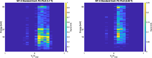
Figure 9. Energy and pitch spectrum of particles reaching the FC-FILD prototype diagnostic being developed for W7-X. No aperture or instrumentation function is applied here. The full (55 keV), half (27.5 keV) and third (18.3 keV) injection energies have been denoted on the y-axis.
Download figure:
Standard image High-resolution image4. Discussion
Simulations assessing the effect of magnetic field strength on fast ion confinement in Wendelstein 7-X have been performed using a newly developed gyro orbit model in the BEAMS3D code. A simple axisymmetric benchmark is presented showing that the code is accurately capturing orbit effects. Simulations comparing collisional confinement in W7-X equilibria with self-consistent profiles show growing disagreement, between gyro center and gyro orbit models, with reducing field strength. Such a trend is expected. The gyro center model is found to over-predict fast ion confinement as the field strength is lowered. Collisionless gyro orbit simulations from the VMEC boundary to the first wall of W7-X show a general trend of decreased divertor loads and increased loads to baffles and heat shield tiles as the field strength is lowered. However, up–down asymmetry persists suggesting a reduced set of possibly critically loaded components to monitor. The MPM mounted NIFS-FILD and FC-FILD shows losses which are predominantly from particles with low pitch angle parameter. This trend holds as field strength decreases, although particles with larger pitch angle parameters reach the detector heads at lower field strength. It should be noted that such studies at fixed kinetic profiles also represent a scan in plasma beta with lower field strengths having larger plasma beta.
From an operational standpoint there appears to be no significant problems arising from operation of the W7-X neutral beam system at lower magnetic field. Confinement at the 1.7 T field strength is similar to 2.5 T and thus performance of the neutral beam system should be similar to that found at 2.5 T. This is important as 1.7 T provides an X3 resonance in the plasma for the ECRH system. Lower field strengths allow for the possibility of achieving higher plasma betas without going to high density or high ion temperature. Key to operating at these lower field strengths will be non-resonant plasma startup by the ICRH system.
Wall load estimates from these simulations should be considered an upper limit as many physical processes are ignored. Wall loads at 2.5 T are qualitatively and quantitatively consistent with simulations by the ASCOT code for the presented parameters [26]. In both codes the region between the equilibrium and the first wall is treated as collisionless. In reality, finite plasma pressure and density can extend for up to 5 cm beyond the VMEC boundary due to the island divertor geometry. Thus slowing down and pitch angle scattering can affect particle orbits. Work to incorporate such effects requires interfacing to edge codes such as EMC3-EIRENE [27], work which is left to the future. Additionally, no electric field is considered outside the equilibrium domain. The presence of such field has been measured (along with a strong shear at the edge), but has not been included in this model. One possibility is to employ an analytic model for the electric field based on edge parameters and connection lengths. Finally, the effect of charge exchange of fast ions has been shown to have a strong effect on loss patterns [28]. All these effects have been neglected in the simulations presented and their inclusion will be the focus of future works.
Finally, it is now possible to begin modeling ion trajectories in the neutral beam box of W7-X, providing improved bending magnet settings and assessment of additional magnetic shielding (figure 10). This can be accomplished by initializing gyro orbit particle trajectories using the neutral beam beamlet model. The beam box CAD geometry can easily be imported into BEAMS3D in the same way the first wall model has been. Magnetic fields from the plasma and magnetic coils (including the bending magnet) are readily available in the code. The missing piece is the ferritic response of the box shielding and bending magnet soft iron. Such simulations can aide in hardening ion dumps, assessing magnetic configurations for neutral beam operation, and assessing the source of any damage found in the box. This would ultimately help in improving the neutral beam pulse length.
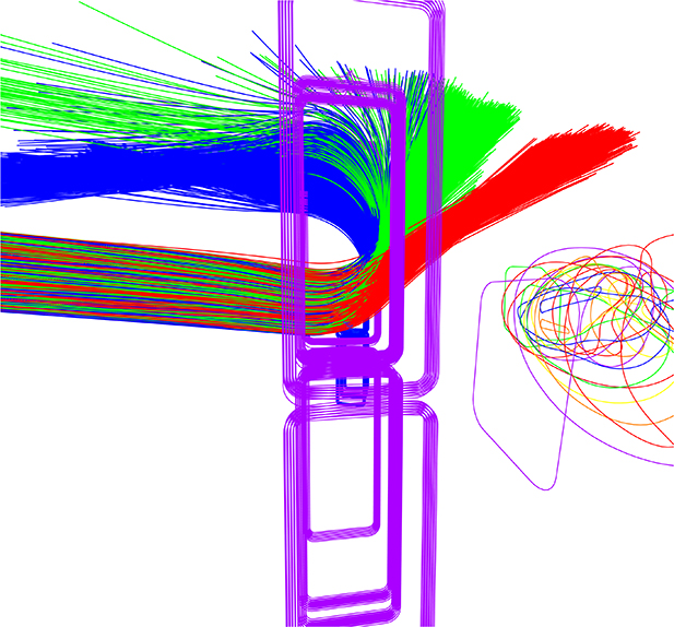
Figure 10. Example simulation of ion beam being bent by the bending magnet in a W7-X beam box. The full (blue), half (green), and third (red) energies particle trajectories are depicted. In the foreground the bending magnet can be seen, and the main coil set of W7-X in the background. No ferritic material is included in this simulation and bending magnet currents are approximate.
Download figure:
Standard image High-resolution imageAcknowledgments
This work has been carried out within the framework of the EUROfusion Consortium, funded by the European Union via the Euratom Research and Training Programme (Grant Agreement No. 101052200—EUROfusion). Views and opinions expressed are however those of the author(s) only and do not necessarily reflect those of the European Union or the European Commission. Neither the European Union nor the European Commission can be held responsible for them. Computing resources for this work have been provided by the 2021 EUROfusion Marconi allocation and resources at the Max–Planck Computational Data Facility.
Appendix A: Gyro orbit equations in cylindrical coordinates
The first and second time derivatives of the position vector ( ) in cylindrical coordinates are written
where  ,
,  , and
, and  the cylindrical unit vectors. Recognizing the that first derivative is just the velocity (
 ) we find our first three equations of motion
where vk are the components of the particle velocity. Our equation for the force acting on a charged particle (Lorentz force is)
where m is the particle mass, q is the particle charge,  is the electric field,
  is the particle velocity, and
  is the magnetic field. We can now equate component wise term in equation (A.2) with this equation and find our second three equations of motion
where we have make use of the electrostatic scalar potential ( ) and the cross product terms of
  have been written explicitly. The last term in equation (A.7) can be identified as the angular centripetal term. The last term in equation (A.8) can be identified as giving rise to the Coriolis effect.
It should be noted that the presence of terms with  in these equations admits possible singularities in the integration domain. This is avoided as the domain of interest is a torus where R > 0, thereby avoiding the singularity at R = 0.
Appendix B: BEAMS3D computational scaling
The parallelization in BEAMS3D utilizes both the parallelization and shared memory features of the Message Passing Interface (MPI) [29]. For quantities which exist only on the right hand side of the ODE's solved in BEAMS3D, shared memory communicators are used. This reduces the overall memory requirements of the code, while simultaneously avoiding expensive data access requests or large broadcasts. The pushing of markers can then be parallelized over each processor, allowing good scaling with problem size (figure B1). For quantities which are integral over the marker population (distribution function), a shared memory architecture is also employed. After the marker push step is complete each shared memory communicator accumulates its data across groups to construct the full distribution function. The parallel features of HDF5 [30] are utilized for writing quantities (such as the marker positions and end states) to the output HDF5 file. An extensive set of tools in Matlab [31] exist for data analysis [32].

Figure B1. Scaling of the BEAMS3D code in gyro center following mode for different computational architectures. The Skylake 8160 and CascadeLake-AP processors have 24 cores per processors while the Skylake 6148 has 20.
Download figure:
Standard image High-resolution image
While extensive benchmarking of the gyro orbit part of the code has yet to be performed, it is found that the gyro orbit runs take significantly longer. For example, a 2.52 T gyro center slowing down run from this work takes 3 h, while the equivalent gyro orbit run takes 22 h. This is attributed to the temporal fidelity of each simulation. Both modes of running the code use the maker initial condition to calculate a time step. For gyro centers this is done using the parallel velocity and a user defined maximum distanced (stereotypically 5 cm). For gyro orbit simulations one eighth of the gyro period is used. This results in nearly an order of magnitude difference in the number of time steps each code performs for this case.