


Abstract
A cross-machine comparison of global parameters that determine the runaway electron (RE) generation and loss process during tokamak start-up was carried out with the aim to extrapolate these to ITER. The study found that all considered discharges, also those that do not show signs of RE, are non-thermal at the start, i.e. have a streaming parameter larger than 0.1. During the current ramp-up the electric field, E, remains above the critical value, Ec, that allows RE in the plasma. The distinction to be made is not if RE can form but, if sufficient RE can form fast enough such that they are detected or start to dominate the dynamics of the tokamak discharge. The dynamics of the value of E, density and temperature during tokamak are key to the formation of RE. It was found that larger devices operate with E closer to Ec, due to their higher temperatures, hence the RE generation is relatively slower. The slower time scales for the formation of RE, estimated to be of the order of 100s of ms in ITER simplifies the development of avoidance schemes. The RE confinement time is also an important determinant of the entire process and is found to increase with the device size. The study also revealed that drift orbit losses, a mechanism often attributed as the main RE loss mechanism during the early tokamak discharge, are actually more difficult to achieve. RE losses might be more likely attributed to RE diffusion due to magnetic turbulence.
Export citation and abstract BibTeX RIS

Original content from this work may be used under the terms of the Creative Commons Attribution 4.0 license. Any further distribution of this work must maintain attribution to the author(s) and the title of the work, journal citation and DOI.
1. Introduction
Tokamak start-up or plasma initiation in ITER may only succeed in a narrow range around a low prefill pressure of the order of about 1 mPa [1]. Consequentially the density during breakdown and burn-through will be low, which is known to increase the likelihood of the formation of a large population of supra-thermal or so-called runaway electrons (REs). RE discharges could damage in-vessel components and should be prevented.
In the first two decades of tokamak research, start-up RE got a great deal of attention [2]. But the focus of RE research has shifted to the more risky formation of RE after a disruption of a tokamak discharge [3]. The generation of RE during plasma initiation has traditionally been linked to too low a prefill pressure for a given toroidal electric field [4]. However, it is now understood that the generation of RE during plasma initiation and early current ramp-up phase is far more complex, depending non-linearly on the dynamics of the electric field and electron density, and various other parameters [1]. Note that in contrast to disruption generated RE, which is driven by the fast drop of the plasma current and cool down of the thermal plasma, during tokamak start-up, the generation current carried by RE, has to compete with the increase of current carried by the thermal plasma [5]. The dynamics will also be influenced by the actions of the plasma control system, complicating the analysis of the RE formation process. Furthermore, the diagnosis of these early plasma discharges is usually far from optimal. Nevertheless, it seems clear that although start-up RE seem ubiquitous in tokamaks, most devices find an operation range that ensures that they dissipate gradually during the current ramp-up when the plasma temperature increases and the thermal plasma becomes a better conductor [3].
The question remains, what determines the operation range that would mitigate RE formation during tokamak start-up? And why do under certain circumstances strong RE beams form? A better understanding of the processes that affect the generation of RE during plasma initiation and practical knowledge of how to manage them, will allow us to prepare better for ITER First Plasma operation. Hence, the International Tokamak Physics Activity for Integrated Operation Scenarios decided to carry out a comparison of observations of start-up RE. The merits of such a study are not only that it shows the scaling of aspects that are relevant to RE formation between these devices. It also ensures one prioritizes observations that are found in all devices, compared to details seen only in singular devices, which may be could be over-interpreted. It can establish a unified view of start-up RE formation, and determine what the critical parameters are that determine the formation process. It will support the development of more accurate models that allow the simulation of RE generation and losses in conjunction with the plasma initiation process [6]. And it will be able to better prepare the operation of future devices and establish improved control strategies that prevent RE during the start-up.
To do so, a large number of observations have been gathered, from a wide range of tokamaks. It collected operational experience related to the start-up RE formation, such as the operating range at which they may occur or schemes or control methods that are employed to avoid them. Furthermore, it constructed a database with a select number of typical cases, from these devices, comprising detailed time traces of important, though basic and global (i.e. 0D) plasma parameters, from which quantities can be deduced, that are relevant to the formation of start-up RE. The limitations of using only global data means that this study may not capture fine details and trends or variations that could be seen on a single device. But data in one device are here complemented by those from other devices, jointly providing a more complete picture. Signs or diagnoses of RE are often arbitrary and not quantitative (i.e. determining parameters such as the RE density or the current carried by RE). Quantitative studies could be performed on a single device by detailed analysis of, for example, the hard x-ray spectra, but this is found too cumbersome for the multi-device analysis carried out here, although it might be an interesting focus for future studies.
This paper is organized as follows, it will first review the physics basis of RE generation in tokamak plasmas in section 2. It will allow us to determine which relevant parameters could be compared and how they relate to the expected RE formation process. Section 3 will provide a more generic device comparison, listing common observations and operation experiences related to start-up RE from the various devices. These may not result in definite conclusions but improve the general understanding of how start-up RE are dealt with operationally. In section 4, a more detailed comparison is carried out. Specific time scales, which are good figures-of-merits of the start-up RE formation, were chosen for this comparison. Such characteristic time scales are for example the times that determine the rate of change in the electric field or the so-called streaming parameter during the early part of the current ramp-up. But there are also the more obvious ones, such as characteristic RE growth times (i.e. inverse growth rates) or the RE confinement time. The scaling of these characteristic times amongst devices will be analysed. Extrapolation of time scales to ITER will allow us to estimate how relevant certain processes related to RE formation will be at ITER. But it will also set benchmarks for RE simulations, or provide requirements for control schemes that prevent start-up RE in this device. Section 5 will summarize the conclusions and provide recommendations for further studies that would strengthen the basis of understanding of tokamak start-up RE formation.
2. Physics basis for the analysis
It is not the purpose to fully review RE theory here, because such reviews already exist [2, 3]. Here the main points and equations that describe RE generation will be summarized and certain definitions will be clarified, such that the analysis provided in the next sections can be understood.
2.1. Definitions
A tokamak plasma may be considered non-thermal but this does not mean it necessarily contains a significant number of RE, merely that the electron energy distribution is non-Maxwellian. The so-called streaming parameter, ξ, can be used to indicate how non-thermal a tokamak plasma is, being the ratio of the velocity needed to carry the current, ue, to the electron thermal velocity, veTH,
Here, ne, Te, e and kB, are the electron density, temperature, electron charge and Boltzmann's constant, respectively, while j is the total current density. It is interesting to consider that an early Townsend discharge, which initiates most tokamak discharges, cannot be considered thermal [1]. But thereafter most tokamak plasmas thermalize, yielding a ξ < 0.1. While strongly non-thermal plasmas are those with ξ > 0.2 [2]. Having, a large streaming factor, and thus a non-Maxwellian electron energy distribution, does not mean RE can exist. RE are those electrons for which the Coulomb collisional drag by the fully ionized plasma is less than the acceleration these particles may feel from any electric field, E. One can show that electrons can freely accelerate, and thus can become REs, RE, if this electric field exceeds a critical electric field, Ec [2, 3, 7],
Here, me is the electron mass and c is the speed of light. For simplicity, the Coulomb logarithm lnΛ is here assumed to be 15 [8]. The critical electric field can be compared with the so-called Dreicer electric field, ED [9], which is the electric field for which the critical velocity for electrons to become RE is of the same order as the electron thermal velocity, thus determined by the temperature, Te (eV), as:
ED is significantly larger than the critical electric field Ec because for tokamak discharges kB⋅ Te ≪ me c2. Assuming Ohm's law (E = η⋅j) and Spitzer resistivity (η ∝ Te −3/2) one finds that ξ (from equation (1)) scales with the ratio of E to ED, with ξ being roughly five times E/ED. Thus the streaming parameter could be used as a proxy for the available at.
Terminology related to fast electrons in a tokamak discharge is often confused. Supra-thermal particles are part of a non-thermal discharge (i.e. ξ > 0.2), however, such particles are not necessarily the same as RE. During tokamak plasma initiation, the discharge may be non-thermal and part of the electrons can be accelerated to relatively higher energies. However, the electron energies may still be limited (<100 keV) due to large losses and time limitations [1]. Later, when the discharge current increases and closed flux surfaces form, the confinement of fast electrons improves, and if still E > Ec, larger populations of actual RE can build up that eventually nearly all reach relativistic speeds. In such a case one can state that the current density, carried by RE is:

Here, nRE is the RE density in the discharge. Note that although for RE the collisional drag is less than their acceleration force, RE still experience collisions, as is obvious from the secondary generation mechanism. But RE can also collide with impurities and neutral particles in the plasma which is known to affect the generation and loss processes of these particles [10–14]. If RE can do damage does not depend on if RE can exist or can be generated in a discharge, or how much kinetic energy each RE could have, but depends on how much current is carried by the RE (IRE) and the magnetic energy this represents [15].
2.2. Dynamics of RE generation
RE can exist if E > Ec, but this criterion does not say anything about how many RE are present in the discharge. For this one has to determine the balance between the generation and losses of RE [3, 16]:
This equation can be converted into one for the change in jRE using equation (4). This considers a primary and secondary RE generation mechanism which are explained in the next two paragraphs, respectively. The third component in equation (5), relates to the RE confinement time, τRE. A factor that may change significantly as the tokamak discharge progresses, as in section 2.3.
The primary generation of RE, Sprimary, from a background electron population with a density ne, temperature Te, and effective charge, Zeff, is usually given as [7, 16]:
It assumes that the background electrons are distributed Maxwellian with a temperature Te. Those electrons with sufficient energy can become RE and these leave the background population. These are then replaced by other electrons via energy-space diffusion, restoring the original background electron distribution function. The primary generation is a very strong non-linear function of E/ED, and one can show that primary generation becomes insignificant when E/ED < 0.013 [17]. Based on the relationship between this ratio and the streaming parameter, plasmas with ξ < 0.065 have no significant primary generation. Effective primary generation, i.e. RE growth that provides a RE current increase significant with respect to the total tokamak discharge current may require values of ξ ≫ 0.065. This will allow us to provide a straightforward check on when this process is active or not. This process becomes more complex, when the background distribution is to be considered non-Maxwellian from the start, or when this thermal distribution changes, for example when Te increases rapidly as is expected during the plasma initiation process in a tokamak [14].
The secondary, avalanching growth rate, in equation (5) can be given as [16, 18]:
Here collisions of high energy incident RE with the background electrons create new, secondary, RE, that could result in an avalanche effect. Note that for secondary generation in a partially ionized plasma, the calculation of Ec, to be used in the above equation, should consider as ne, the density of both free electrons and bound electrons [18] and also modify the Coulomb logarithm to include bound electrons [16].
The above two equations are all derived under certain conditions and with certain assumptions. The primary growth assumes a Maxwellian energy distribution for the background electrons in a plasma that is fully ionized, for which part of the population shifts towards relativistic RE. But during the early stages of a tokamak discharge, the assumption of a Maxwellian distribution does not apply. Moreover, the presence of neutrals in a not fully ionized plasma may slow the RE generation [1]. Similarly, secondary generation as derived above assumes RE can freely increase and that the incident RE have infinite energy [18], while the incident RE energy may actually be limited. This would mean that the secondary generation according to the above equation might be overestimated, especially for cases when E is only slightly above Ec [19–22], as also was observed experimentally [5].
Finally, the growth of the RE population, given by equation (5), will need to compete with the growth of the thermal population. This is a significant difference with RE generation after a tokamak discharge disruption, when the thermal plasma collapses (i.e. a fast decrease of Te, to very low values of a few eV) combined with a quench of the current, the latter increasing E. The change in jRE is given by equations (4) and (5). However, this is coupled to the dynamics of the thermal current, jTH, via the circuit equation:
Here the total current, I = j⋅Ac, where Ac is the poloidal cross-section of the plasma and j = jTH + jRE. Ltor is the inductance of the toroidal plasma, with VI being the inductive voltage and VL being the externally applied loop voltage, and R being the resistance. Parameters such as Ac and Ltor are, for simplicity, assumed constant in time, but these may change considerably during the plasma initiation process. VR is the resistive voltage which is related to the electric field, E as E⋅2⋅π⋅ro = VR, where ro is the device major radius. It is this E that generates RE and enters the primary and secondary growth rates given above. Note that it is usually assumed that the resistive voltage is equivalent to ITH⋅RTH. As is shown in [5], a fast increase in total current, I, either due to a controlled ramp of the thermal current, or a too fast increase in jRE, will reduce, via equation (8), VR, thus E, and as a result, limit the growth of RE. Note, that one cannot neglect VI, in the absence of any thermal plasma, for example when the discharge has converted to a full RE beam, and I = IRE. Equation (5) shows that even for a constant value of nRE and thus jRE, one needs some RE generation to compensate for the losses, hence a value of E > 0. Indeed, under such circumstances the RE discharges were shown to require a small VI and VL, to maintain a constant current [5].
The critical issue with start-up RE formation, is not if they form, thus if E > Ec, or if one obtained positive growth from equation (5), but if sufficient RE are formed that (1) their dynamics affect equation (8), and other aspects of the thermal plasma, (2) RE can damage in-vessel components as has been noted before. The first point would be met if simply jRE ∼ j, although already before that, significant levels of jRE would reduce jTH and thus also reduce the ohmic heating that is relevant to maintain the thermal plasma, eventually leading to a collapse of the thermal plasma and the formation of a full RE beam, i.e. all current is carried by RE [5]. The second point would mean that IRE reaches a critical value that in part may depend on the wetted area on which the RE energy is deposited [15].
To calculate the full dynamics of start-up RE, one needs to solve the coupled equations for the RE generation and RE and thermal currents, further coupled with the development of the thermal plasma, that describe the dynamics of the ne and Te, and the linked resistance, similar as is done in some plasma initiation simulation codes [6, 23, 24].
2.3. RE energy
RE are expected to have high energies and as noted above, however, it takes time for these particles to gain energy. It is worth looking into, how long it takes for them to reach certain energies, and what may limit their energy in the end. It takes 5–12 ms for an electron to be accelerated to 95% of the speed of light, c if it experiences an electric field of E = 0.7 V m−1 and E = 0.3 V m−1, respectively [5]. For higher energies, the energy of a relativistic RE being accelerated by an electric field E(t) can be approximated as:
Here, γ is the relativistic correction factor. The RE energy, WRE, in units of MeV, is given by the conversion: WRE(t) = 0.51⋅(γ(t) − 1) in MeV. If the thermal plasma develops well and becomes more conductive, the discharge would have a small VR and thus low value E, hence it might take a considerable time for RE to gain multiple MeV energies.
The duration of the acceleration is however limited by the time during which the RE is confined, i.e. τRE. This will set a limit to the maximum energy that can be achieved by RE during the current ramp-up. Early in the tokamak discharge, when characteristic closed magnetic flux surfaces (CFSs) have not yet formed, relativistic RE may not be able to exist, simply due to the fast parallel losses of such particles. Prior to the formation of any local CFS, only very limited energies (i.e. several 100 eVs) can be achieved [1]. Hence, to in the above equation is best considered as the time when CFS form. The next energy limitation that is traditionally quoted to be relevant to start-up RE, relates to so-call drift orbit (DO) losses. For highly energetic RE, the DO will be such that they intersect with the vacuum vessel, and thus such particles will be lost [2, 25, 26]. Assuming a constant distribution of current density, for a given total current, I, a maximum RE energy for which the trajectories remain within the tokamak, is given by [2, 27]:
Here, I is in MA and rout is the radial position of the outer limiter that intersects with the RE trajectory and thus where it is lost, while rin, is the location where the RE is formed, which could be considered the plasma centre (ro) or further inward. Both rin and rout are related to ro, and a, the plasma minor radius. It can be shown that the geometric factor for most tokamaks is of the order of Fgeom ∼ 0.2–0.4 and that it scales approximately with the inverse aspect ratio, ε = a/ro. For more peaked current profiles, the DO are slightly better confined [2].
As the current ramp-up progresses, according to equation (10), the confinement of higher energy RE improves. However, microscopic or macroscopic magnetic field perturbations, such as the magnetic field ripple, are known to affect RE motion as well, limiting their life-time in the plasma, and thus the maximum energy they can obtain. If RE reach energies of several MeV, direct energy loss due to synchrotron emission starts to dominate and thus determine the maximum energy they can obtain [27, 28].
2.4. RE confinement time
One of the key time scales concerns the RE confinement time, τRE, as used in equation (5). The previous section (section 2.3) has already alluded to the connection between τRE and the maximum RE energy.
The time, non-relativistic electrons can be accelerated along open field lines (OFLs) of a length, L, is equal to [4]:
This can be considered a confinement time, prior to the formation of any CFS. For E = 0.3 V m−1 and L = 10 000 m, this gives times that are sub-milliseconds. Under these circumstances, electrons are unlikely to reach very high energies, which are usually limited to well below the MeV level.
But, as noted in the previous section (section 2.3), when CFS form their confinement improves significantly. RE can now be confined up to the point they are accelerated to such high energies that their DO become too large. Assuming a constant acceleration (i.e. E) and constant value of I, from equations (9) and (10) a confinement time can be derived:
Here, the current I is in units MA. For I = 1 MA and VR = 0.2 V, and ro = 3 m (i.e. JET start-up values), this confinement time is of the order of τRE DO ∼ 6–10 s. This value should be considered an order of magnitude estimate for τRE DO and larger confinement times for JET have been found [5]. This confinement improves linearly with the total current, thus RE confinement due to DO losses would improve as the current ramp-up progresses. From the above equation, one can deduce that this confinement times scales stronger than linear with the device size (i.e. ro), because the device current I, also is a function of its size.
But other loss mechanisms exist. Micro-scale magnetic turbulence in the plasma is capable to diffuse RE orbit from the core of the plasma towards the edge [29]. This so-called Rechester–Rosenbluth (RR) diffusion depends on the level of magnetic turbulence, δb, relative to the total magnetic field, BT: b = δb/BT. This effect varies per device and depends on the RE energy as well [27, 30]. The relative level of magnetic turbulence in a tokamak discharge is estimated to be of the order of b ∼ 10−4–10−2 [30]. A confinement time can be derived from the diffusion coefficient, DRR that is thought to be proportional to the b2, the RE speed, which is assumed to be the speed of light, and the distance the RE travels through the plasma, estimated to be ∼ π⋅q⋅ro [29]:
Here, q is the safety factor. For this loss mechanism, the confinement time is shorter for a higher level of b. Note that in this case, the exact values of this confinement time are more difficult to assess. Not only because the level of b is not well known, but also because of the arbitrary assumed value of S. Moreover, RE diffusion is affected by their energy [30] and this is thought to be related to the partial de-correlation from the magnetic turbulence, at higher RE energies [31]. Hence, corrections to the above equation (13) are needed that reduce the losses of higher energy RE. It is therefore difficult to accurately assess the value of τRE RR. It has been reported that the RE diffusion can vary between DRR ∼ 0.001–1 m2s−1 [30] and in JET would be of the order of DRR ∼ 0.03–0.2 m2s−1 [5, 31] suggesting for JET τRE ∼ 4–20 s, which is similar to the value estimated for drift-orbit (DO) losses. Equation (13), gives some insight into how this RE confinement time scales from device to device. If one assumes that the level of magnetic turbulence is smaller in larger devices, this would again suggest that this RE confinement time scales stronger than linear with the device size. Interestingly, this confinement time would also increase during the current ramp-up, via its relationship with q.
None of the above mechanisms takes into account RE losses due to short bursts of macro-scale Magneto-HydroDynamic activity or possible non-linear RE-plasma wave interaction that may occur during plasma initiation or the early current ramp-up phase [32–37]. These effects could result in short bursts of RE losses, decreasing the average overall RE confinement.
2.5. Other scaling parameters
The above time scales on which RE can be formed and lost can be compared to a number of other basic time scales relevant to plasma initiation and tokamak start-up. According to the circuit equation (equation (8)), the (RE) current rise is always limited to:
Thus from equations (4) and (5), one can show that there is a simple limit to the primary growth rate, Sprimary, as E/ED is limited, under tokamak start-up conditions. This is opposite for RE generated during a disruption, for which the quench of the current, in contrast to an increase I, actually drives the electric field, thus much higher values of E/ED can be achieved, than the limit shown here. The above equation will also set a limit to the time large RE beams can develop during start-up conditions.
A second important time scale is the duration of the current ramp-up, Δtramp-up, which scales with the resistive time as, τR, as:

where η is the plasma resistivity (i.e. Spitzer resistivity, assuming a predominantly Maxwellian electron energy distribution). As will be shown later, the duration of the RE generation and dissipation process often far exceeds the plasma initiation stage, and continues long into the current ramp-up for most tokamaks.
3. Multi-device comparison
From each participating device, general observations and experiences were collected, as well as a select set of discharges that allowed comparison of those that formed strong RE activity and similar ones that had more benign or no RE activity. However, such classification is rather arbitrary, because the RE diagnostics per device vary widely, and most provide indirect evidence of the presence of RE, rather than direct measurements of their total number (density) or the total current carried by RE. Therefore, a case classified as one having strong RE activity in one device, may not be detected as such elsewhere. Only in a few cases, RE activity was such that it affected the tokamak discharge dynamics, for example causing an emergency stop, or that RE impact on the in-vessel components caused damage.
Table 1, provides a summary of those devices that participated in this study, ranking them according to a number of device characteristic parameters, as well as lists the pulse numbers that make up the database of discharges. It shows the wide range of device sizes (ro, a, Ac and aspect ratio, ε) used in this study. Similarly, the variance in BT/ro is large as well. Note that here not the full device range of BT is given but the value closest linked to the data set that was provided for this study. The inductance, Ltor, has been calculated, taking into account effects of aspect ratio and elongation that are for example relevant for the NSTX cases [38]. The typical duration of the time to ramp up the plasma current, which depends on the device's resistive time, varies by more than two orders of magnitude. Later other typical time scales will be studied, but first, a general comparison will be carried out. Those few cases, for which RE caused damage have been indicated in bold in the table.
Table 1. For each device, the symbol used in the figures shown in the remainder of this paper, are given, the major and minor radius, ro and a, the volume of the device vacuum vessel, Vv, the device toroidal magnetic field, BT. The typical poloidal cross-section of a plasma, Ac, its inductance at start-up, Ltor, the ratio of the loop voltage, VL to Ltor, and the typical duration of the current ramp-up phase (again for the data set provided here. Note that here not the full device range is given but values linked to the data set that was provided for this study, and focuses on values during the plasma initiation and early current ramp-up. Those cases, for which RE are known to have caused damage to in-vessel components are indicated in the table in bold.
| Device | Sym. | ro | a | Vv | BT | Ac | Ltor | VL/Ltor | Δtramp | Submitted pulses |
|---|---|---|---|---|---|---|---|---|---|---|
| m | m | m3 | T | m2 | μH | MA s−1 | S | |||
| C-MOD | ▪ | 0.68 | 0.2 | 4 | 5.4 | 0.2 | 1.1 | 4.3 | ∼0.5 | 1080326001, 1080326002, 1080326005, 1100309002, 1100309009, 1100309010, 1100309011, 1100309019, 1100309021 |
| FTU | • | 0.94 | 0.3 | 2.5 | 6.0 | 0.3 | 1.6 | 7.1 | ∼0.16 | 35959, 36205, 37405, 37407, 39400. |
| ITER | ♦ | 5.7 | 1.6 | 1000 | 2.65 | 8.0 | 12 | 0.9 | ∼60 | DINA start-up simulations: 15MA-DINA2017-1, 15MA-DINA2017-2 |
| JET | ▲ | 2.9 | 0.7 | 180 | 2.4 | 3.5 | 4.9 | 1.5 | ∼4.0 | 81321, 80258, 80259, 80260, 80262, 80263, 80265, 80266, 80267, 80268, 80269, 80270, 80272, 80273, 80274. |
| KSTAR | ▪ | 1.8 | 0.4 | 56 | 1.8 | 0.8 | 3.5 | 0.8 | ∼0.85 | 25632, 25679, 26031, 26080, 26121, 26390, 26406, 26456, 26505, 26552, 26602, 26618, 26619, 26647, 26696, 26742, 26923, 27178, 27213, 27340 |
| NSTX | ▲ | 0.82 | 0.62 | 28 | 0.4 | 2.2 | 0.38 | 6.7 | ∼0.15 | 111294, 111296, 111297, 111300, 111301, 111304, 111307 |
| WEST | • | 2.5 | 0.4 | 50 | 3.6 | 0.9 | 6.1 | 2.5 | ∼1.5 | 52205, 52526, 53141, 53146, 53853, 54468, 54469, 55381, 55414, 55490, 55636, 55672, 55678, 55899, 55900, 55902, 56548, 56598, 56720 |
The study included devices that have metal plasma-facing components, such as FTU, C-MOD, JET and WEST, while others operated with a standard Carbon based first wall. KSTAR and WEST are the only existing tokamaks in this study that makes use of super-conducting magnets, as ITER will also deploy in the future. Several of these devices have reported over the years, individual studies on specifically start-up RE, such as notably FTU [39–43], JET [5, 31, 44, 45], to some extend also C-MOD [46], NSTX [47] and recently WEST [48–52]. Other notable references to start-up RE from devices, not included in this particular study are [25, 26, 30, 33, 36, 53, 54].
The experimental data can be compared to ITER cases that have been simulated either by the SCENPLINT [6] or DINA codes [55], the former simulating details of breakdown and plasma initiation, while DINA simulations of typical ITER current ramp-up cases to I = 15MA have been provided, of which one of them (15MA-DINA2017-1) concerns an Ohmic current ramp-up, while the other (15MA-DINA2017-2) has electron cyclotron heating (ECH) applied after the plasma configuration has been diverted.
3.1. General device comparison
In figure 1(a), the spread off all cases in the database, in the parameter space of EL versus the prefill pressure, pn, at the time of breakdown is shown. Here EL is the externally applied toroidal electric field in the centre of the device, equivalent to VL/2πro. Some of the cases do not show clear signs of RE activity, others do, thus figure 1(a), shows that there is not a direct relationship between the range of EL or pn and the observed RE activity. The figure merely shows the general range at which the devices operate their breakdown and plasma initiation and both cases that form strong RE signs and those that do not show clear signs of RE fall in similar areas. Interestingly, it also shows that the super-conducting device KSTAR has breakdown conditions that are close to those of ITER. The ITER cases, in figure 1, are from a series of simulations of ITER plasma initiation, using the SCENPLNT code [6]. The cases studied here can be spit up, by those that have generally a lower EL (i.e. here JET, NSTX, KSTAR and ITER) and those that have been achieved with a higher EL (i.e. FTU, WEST, C-MOD).
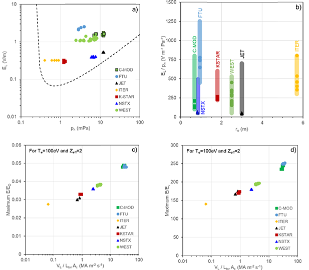
Figure 1. (a) Scatter plot showing the breakdown operation points of all cases considered in this multi-device database, in the electric field (EL) versus prefill pressure (pn) space. For reference a Paschen curve for breakdown in hydrogen with a connection length of L = 1000 m is shown. (b) The operation range for ratio EL/pn for a few devices, compared to the ITER operation point, plotted arbitrarily against major radius, ro. The values for the individual cases submitted for this study are also shown. (c) The value of E/ED needed to achieve a current density increase purely due to primary generation, i.e. e⋅c⋅Sprimary(E/ED), being equivalent to the maximum VL⋅Ltor −1⋅Ac −1 for Te = 100 eV and Zeff = 2 (d) the same limit but converted to E/Ec.
Download figure:
Standard image High-resolution imageHere, only the cases that make up this specific database are shown, and the plasma initiation operation range is usually larger, as can also be seen in [5, 47]. The full device operation range was provided for all devices in the database, and the range of the ratio EL/pn, and these ranges are shown in figure 1(b). Most devices have operated around the ITER operation point of 300 V m−1 Pa−1 (for EL = 0.3 V m−1 and pn = 1 mPa). For the C-MOD case, RE are generally observed if available at: >400 V m−1 Pa−1. However, the specific RE case supplied to this study had much lower values. Also, the cases chosen for NSTX, KSTAR and JET, for which several showed clear signs of RE, are actually near the lowest limit of the EL/pn range. It suggests that value for EL/pn does not seem to be of importance for start-up RE formation. No clear EL or pn range can be indicated, general to all devices, for which start-up RE would form.
During the tokamak start-up, the current dynamics should obey equation (8), hence setting an absolute limit to the maximum possible current rise, in the tokamak, given by equation (14). This limit depends on the applied loop voltage and the size of the device, via Ac and Ltor. In figure 1(c) is shown that this also sets a limit to the maximum possible value of E/ED. This maximum is determined by finding the value of E/ED for which e⋅c⋅Sprimary(E/ED) = VL⋅Ltor −1⋅Ac −1 for a fixed value of Te, here chosen to be 100 eV and Zeff = 2, typical for the early current ramp-up. For practical reasons, this limit is converted in the maximum value of E/Ec, for a fixed Te = 100 eV as shown in figure 1(d). Higher values of E/ED and E/Ec (for Te = 100 eV) are not possible. For higher values of Te, the E/Ec limit decreases while the maximum value of E/ED increases. Interestingly, the variation of the maximum value of E/ED and E/Ec is significantly smaller than the range of values of VL⋅Ltor −1⋅Ac −1, because Sprimary scales strongly with E/ED. This absolute maximum of E/ED for tokamak start-up is always well below unity, while the maximum for E/Ec is of the order of 102. Secondary generation at this very early stage of the discharge may not be relevant yet, because not sufficient RE seed might have built up. However, it is worth considering that for very high values of E/Ec, the secondary growth rate might well be higher than that given by equation (7) [56].
In figures 2–4, a few cases of each device are shown, one or more that develop strong signs of RE (often shown in red), another with very similar EL and pn, for which no RE are detected (shown in green), and for some devices, an intermediate case (shown in yellow), for which RE are observed, but these dissipate later in the discharge. This point is also an important feature of start-up RE: they can form, and increase but also dissipate and decrease on a time scale shorter than Δtramp-up. This again means that in such cases, the RE density growth as given by equation (5) becomes negative, either because of negative secondary growth or too short a confinement time. A detailed look into the figure will show that the dynamics of a number of parameters, such as the streaming parameter, the resistive electric field E, and the density all matter in determining if RE become prevalent or not. Most devices show striking similarities, while there are also differences. Specifically for JET, one case (80263), shows the generation of a discharge for which the current is carried fully by RE, as reported in [5]. The initial development of this discharge is indistinguishable from the preceding case 80262, which only showed moderate and temporary signs of RE. This last case is close to JET discharge 81231, also shown, which was analysed in detail in [45], showing that in this case, the IRE increased and peaked at IRE ∼ 40 kA (approximately 2%–3% of the total current) before dissipating slowly.
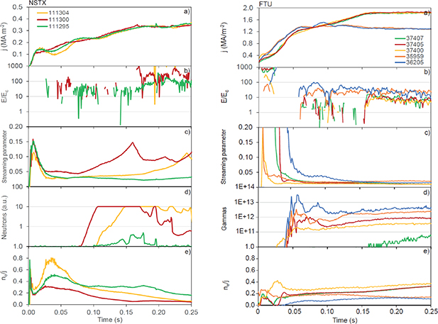
Figure 2. Two sets of cases from NSTX and FTU, in green a case with little or no RE activity, in yellow, one with intermediate or short-term signs of RE activity, and in red, a case with strongest RE activity. In blue additional interesting cases are shown. The figure shows for the duration of the current ramp-up of these discharges (a) the current density, j, (b) the ratio of E/Ec, (c) the behaviour of the streaming parameter, (d) the device typical method to detect the presence of RE, (e) the behaviour of the ratio of ne and j, in units 1020 m−1 MA−1.
Download figure:
Standard image High-resolution image
Figure 3. Two sets of cases from C-MOD and KSTAR, in green a case with little or no RE activity, in yellow, one with intermediate or short-term signs of RE activity, and in red, a case with strongest RE activity. In blue additional interesting cases are shown. The figure shows for the duration of the current ramp-up of these discharges (a) the current density, j, (b) the ratio of E/Ec, (c) the behaviour of the streaming parameter, (d) the device typical method to detect the presence of RE, (e) the behaviour of the ratio of ne and j, in units 1020 m−1 MA−1.
Download figure:
Standard image High-resolution image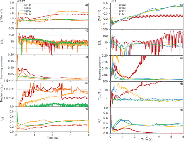
Figure 4. Two sets of cases from WEST and JET, in green a case with little or no RE activity, in yellow, one with intermediate or short-term signs of RE activity, and in red, a case with strongest RE activity. In blue additional interesting cases are shown. The figure shows for the duration of the current ramp-up of these discharges (a) the current density, j, (b) the ratio of E/Ec, (c) the behaviour of the streaming parameter, (d) the device typical method to detect the presence of RE, (e) the behaviour of the ratio of ne and j, in units 1020 m−1 MA−1.
Download figure:
Standard image High-resolution imageFor each device a different time window is shown, focussing on the approximate duration of the current ramp-up. This differs for each device, being significantly longer for larger, devices, as the current ramp-up time, in general, scales with the current diffusion time. The total current density, j, per device also varies, with those devices that operate at a higher BT, also having a larger, j.
The first observation relates to the behaviour of the ratio of E/Ec, which for most devices is well above unity at the time of plasma initiation but gently decays to lower values as the current ramp-up progresses, although it never seems to fall below unity. The general trend for the decrease of E/Ec during the tokamak start-up is due to the general increase in ne, combined with an increase in Te, thus a reduction in E. An exception is NSTX which provided cases that suggest an increasing value of E/Ec over time, linked to the decreasing value of ne/j. The latter is purposefully done, to experimentally generate RE during the start-up. The reason for the noisy traces for nearly all devices is that in order to determine the value of E, the inductive voltage has to be subtracted from the measured externally supplied electric field, and inaccuracies in the knowledge of the value of Ltor, and the determination of the derivative of the total current, add up to large errors in the value of E. Nevertheless, one can state that all of these devices seem to operate during the current ramp-up with E/Ec > 1, an aspect that will be looked into further, in section 4.
Secondly, the behaviour of the streaming parameter shows, that all devices show to be non-thermal (i.e. the streaming parameter higher than 0.1 are common at this stage of the discharge) at the time of plasma initiation, but in general the discharges thermalize (i.e. ξ < 0.05) around about a tenth of the duration of the current ramp-up, especially those, that do not have any significant signs RE activity. It suggests that all cases are non-thermal around the time of plasma initiation, i.e. the electron energy distribution is non-Maxwellian, though it does not mean there is yet a significant RE population. For a few notable cases, the streaming factor starts to increase again well above ξ > 0.1 later in the current ramp-up, while also measurements of RE activity are high. The latter suggests a dangerous non-thermal discharge, likely with a large fraction of the current carried by RE. In these figures, such cases are shown from NSTX and JET, but similar cases also exist, for example, for C-MOD. Note that for all devices, the RE activity increase (generation) and dissipation (losses) extend well into the current ramp-up phase. Thus start-up RE is definitely not a mere plasma initiation issue. It should be reminded that dynamics of ξ are a proxy for those of E/ED, dynamics as noted in section 2.2.
The final point relates to the behaviour of the dimensionless parameter ne/j. It is nearly equivalent to the Greenwald fraction, fGW [57], but this ratio is also known from the early days of tokamak operation as an indicator for the presence of RE activity [2, 58]. The ratio is inversely proportional to the streaming parameter and is often seen as more practical to calculate as it would not require Te. Discharges with low values of ne/j are known to be prone to RE activity, which is also clear from figures 2–4, for the NSTX, KSTAR and WEST cases, for example. However, no clear separation is visible, and no clear criterion can be given for a value of ne/j, above which RE activity would not be seen.
3.2. Survey of RE experiences
Besides collecting and comparing measurements, the survey also collected general experiences, related to start-up RE, which will be summarized here. Although one may perceive these points as conjectures that are not necessarily backed by actual scientific studies, it was thought that listing these observations, often found at multiple devices, are important to prepare ITER plasma operation such that one prevents too strong RE activity during its start-up. The following observations were made:
Start-up RE observations are often found when a tokamak carries out its first plasma operation or first operation after a major upgrade. The plasma start-up dynamics, and especially that of the density, may differ from what is expected during such first operations. Such differences in density behaviour led to start-up RE, when JET transitioned from a carbon-wall to a beryllium main chamber wall [5, 59, 60], and this was also observed during first operation of WEST that used a full tungsten wall [48]. Differences in recycling in tokamaks with full metal walls can lead to lower-than-expected densities during the early stages of the tokamak discharge, generating start-up RE. But such events were gradually prevented in both devices after careful tuning of the waveform requests and changes to density control. A link with device conditioning that improves gradually after first plasma operation, is also possible. Erroneous tokamak control actions, especially related to the density control or the continuous application of VL that keeps the RE formation going, can make things worse, as has been seen in JET [5]. In general, a strong relationship between the occurrence of RE activity and the density or Greenwald fraction: too low a density (due to low prefill pressure, density control problems, too high pumping (e.g. during X-point formation, wall recycling) is observed. Already in the early days of tokamak research, it was known that a higher value of I/ne seems to make start-up RE more likely [2]. For smaller devices, the prefill is often the key factor to control the density during the plasma initiation or early start-up, but for larger devices density control and wall conditioning may become more relevant. The influence of plasma impurities on the RE formation was already noted in section 2, but not further pursued in this study, because this is better done, in a single-device experiment, allowing easier comparison of impurity measurements.
Tokamak discharges with and without start-up RE activity are difficult, or sometimes impossible, to separate. Most of those that show early signs of supra-thermal or REs (e.g. supra-thermal electron cyclotron emission (ECE) or hard-x-rays), thermalize later during the ramp-up stage (i.e. RE activity diminishes). In rare occasions, however, the number of RE increases to such an extent that their loss damages in-vessel components. Many of the discharges that show signs of RE during the start-up do not cause problems or damage. Their presence might often be overlooked. It is not the presence of RE themselves, but the amount of RE that is generated that is the problem. It has been known that disruptions during the current ramp-up, are more prone to form large RE beams, compared to when this happens during the flat-top phase of the tokamak discharge. This might be interpreted by the presence of some RE seed, during all tokamak current ramp-up.
The conversion of the entire current being carried by RE is a worst-case scenario, which obviously leads to damage when such RE beams are lost and the energy is deposited on in-vessel components, as has been seen at JET [5]. However, even without such a conversion to a full RE beam, start-up RE can cause damage. At the start of WEST operation RE generated during plasma initiation were able to damage in-vessel components, generally simultaneous with the quench of the current, either due to burn-through problems, or when the plasma disruption in the early stages of the discharge [48, 49, 52].
Tokamak plasma initiation is often supported by means of radio-frequency (RF) heating methods, such as ECH. It is known that the wave electric fields of these heating methods are capable to accelerate electrons to high energies [61], hence, the application of RF heating can provide an additional RE generation mechanism. However, an accurate ECH RE source model is not yet available. Experimental evidence of such a source has been reported [41, 42]. On the other hand, auxiliary heating in general might also provide a beneficial effect by augmenting the plasma temperature and hence decreasing its resistivity and thus the required E during the current ramp-up, which aspect is shown in more detail in section 4.
There is a big variation in the method of diagnosis of RE and the accuracy of detection varies. This makes a general classification, device comparison or benchmarking of simulations difficult. RE are usually observed (e.g. by supra-thermal ECE, neutrons that are emitted, or hard x-rays/gamma rays [2]) even while the streaming parameter indicates that the plasma in general terms is thermal. However, all these diagnostic methods, only indicate more RE are present in one discharge compared to another, but this difference is rarely quantifiable, nor is it possible to compare observations from devices. Such issues with diagnosis can also result in a misinterpretation of the RE detection, as the qualitative detection method may not be able to correctly determine the risk of damage due to RE.
4. Comparison of time scales
In this section, specific parameters and time scales will be derived from the time traces provided for all cases in the database, to be compared per device. At each device, different methods are used to determine if RE are present or not. Most use hard x-ray emission (KSTAR), gamma-ray emission (WEST, JET, FTU, C-MOD, NSTX), or neutron yields (NSTX, FTU) as indicators for RE, but also supra-thermal ECE can be used (KSTAR, JET, WEST). As noted before, these are all indirect methods to determine the presence of RE, and these diagnostics do not provide quantitative measurements of the number of RE, or nRE. For each diagnostic method, at each device, thresholds can be assumed that would indicate the presence of RE. In figure 5, for each case that has RE activity, the time is shown (after the start of the discharge) when this (very arbitrary) threshold is passed, defined as the 'RE detection time'. The used threshold, X, for the RE detection methods shown in figure 4(d), is given in the legend of figure 5. The figure also shows a wide variation in the detection times for an individual device is possible due to differences in the RE development for the selected cases. Some sort of ordering with Δtramp-up seems possible but should not be considered causal. But the comparison from device to device is likely governed by the differences in diagnostic sensitivity that are available per device. One can roughly say, that most devices detect RE about a tenth into the current ramp-up, thus after >0.1 × Δtramp-up. But the comparison from device to device is likely governed by the differences in diagnostic sensitivity that are available per device. In figure 5, those cases for which RE losses are known to have caused damage (as indicated in bold in table 1), have been labelled specifically. It shows that such cases are not necessarily detected earlier.

Figure 5. The arbitrary RE detection time, determined as the time when the RE diagnostic signal exceeds a device-specific threshold. This threshold is determined per device/diagnostic, by comparing various cases, that show RE activity and those that do not. The RE detection time is plotted versus the current ramp-up time, Δtramp-up. Those cases that cause damage due to RE losses (as indicated in table 1), have been labelled specifically with a red border.
Download figure:
Standard image High-resolution image4.1. Aspects related to RE generation
The second aspect to investigate concerns the behaviour of the streaming parameter. As is shown in figures 2–4, for most devices, the streaming parameter suggests a far from thermal plasma, during and right after the plasma initiation, even for those cases that later do not show any clear RE activity. For all cases, the streaming parameter, ξ, decreases rapidly, indicating a thermalization of the discharge. As explained in section 2.2, the value of the ξ is linked to E/ED and for too low values ξ < 0.065, primary generation would become negligible. The streaming parameter is easier to determine experimentally, while the value of E/ED is prone to large errors in the determination of E, as noted in section 3.
In figure 6(a), the time for which ξ decreases after plasma initiation below a value 0.065 (tξ < 0.065) is shown for all cases (including those that do not show clear RE signs). The ordering by Δtramp-up seems to work again. Roughly, the primary generation becomes negligible 10% into the current ramp-up (at t = 0.1–0.9× by Δtramp-up). But there is, per device, quite some variation. These variations in tξ < 0.065 are due to differences in the detailed behaviour of ne and Te, with respect to the current rise. Those cases, for which this specific time is longer, will generate a larger seed of RE by primary generation. This is clearest seen for specifically KSTAR as shown in figure 6(b). The KSTAR values of tξ < 0.065 for the cases in the database vary nearly one order of magnitude. For those KSTAR cases for which tξ < 0.065 is the longest, RE are detected earliest. Thus most cases that show clear and early signs of RE activity lie at the upper part of figure 6(a), however, a clear trend, as is seen in KSTAR, is not found in all devices. Variations in the observations of RE, are not only due to the strength and duration of the primary generation but can also be caused by differences in the secondary generation that can enhance any seed, even weak. In figures 2–4 it can be seen that in some cases, ξ starts to increase again, to higher values later in the ramp-up. These cases will be discussed in more detail in section 4.5. In figure 6(a), those cases for which RE losses are known to have caused damage (as indicated in bold in table 1), have been labelled specifically. The WEST case with a short value tξ < 0.065 contrasts here against the two JET cases and the C-MOD example.
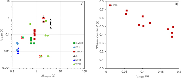
Figure 6. (a) The time for the streaming parameter ξ to decrease below 0.065, right after plasma initiation, plotted against Δtramp-up. (b) The observation time of RE specifically for KSTAR, defined as the time when the hard x-ray count exceeds a value of 10 (see also figure 3(d)) plotted versus the time needed for the streaming parameter ξ to decrease below 0.065 (tξ < 0.065). Those cases that cause damage due to RE losses (as indicated in table 1), have been labelled specifically with a red border.
Download figure:
Standard image High-resolution imageDuring the current ramp-up phase usually ne increases while E decreases, as the thermal plasma resistivity decays with an increasing temperature. Although there are some counter-examples shown in figures 2–4, for example for NSTX and FTU, for which the ne is kept (intentionally) at very low levels. For all cases, the average value of E, and ne have been determined over a time interval from 0.1 to 0.9 × Δtramp-up and these values are shown in figure 7(a). This averaging reduces the large error in the measurement of E. Error bars are added in figure 7(a ) to indicate the temporal variation in E and ne during the averaging time interval. The two cases of DINA simulated ITER ramp-ups to I = 15 MA have also been included for comparison. As obtained from figure 1(d), the upper boundary is set by the values of E/Ec (∼150–250) during the plasma initiation (thus prior to 0.1 × Δtramp-up). But soon after plasma initiation, the values will have to decrease below E/Ec < 50. Above this value, it is possible to obtain primary RE generation that yields a RE current increase that would violate the criterion set by equation (14). Figure 7(a) shows that the values of E/Ec (averaged over the current ramp) generally fall in the range E/Ec ∼ 10–30, suggesting secondary generation could effectively enhance any RE seed. The only exceptions are the largest devices JET and ITER, for which E is close to or just below Ec. NSTX shows the highest values of E with respect to Ec. But as is shown in figure 2, the density is purposely decreased during the current ramp-up of the NSTX cases, to create circumstances for RE formation.
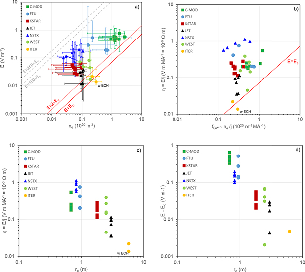
Figure 7. (a) The averaged value of E versus ne, for all cases during the current ramp-up. The error bars indicate the variation of the values during the averaging time interval from 0.1 to 0.9× Δtramp-up. The solid, dotted and dashed lines indicate the values of E = Ec, 2⋅Ec and the range where E is between 150⋅Ec and 250⋅Ec, respectively. (b) The same data (without error bars) but both axis normalized by the average current density, j, thus showing E/j = η versus ne/j ∼ fGW. (c) The same data (without error bars), now showing the value of E/j = η versus the major radius, ro, (d) the difference between E and Ec, plotted versus the major radius, ro. The ITER case that is simulated with ECH during the ramp-up is specifically indicated (though absent in figure (d) as the E − Ec value is below zero).
Download figure:
Standard image High-resolution imageFigure 7(a) can be normalized by total current density j, which converts the y-axis into the averaged resistivity and the x-axis a value similar to the Greenwald fraction, fGW, as is shown in figure 7(b). If the resistivity values are plotted against the device size (ro) as is shown in figure 7(c), it becomes clear that larger devices, with higher Te, operate at lower values of E during the current ramp-up. Less clearly visible, is the feature that devices with a higher BT, such as C-MOD and FTU, operate generally at higher ne, thus lower Te, and consequently higher values of E. Notably, the ITER case that makes use of ECH during the current ramp-up is the one that shows the lowest value of E and the lowest value of η.
The secondary growth rate is theoretically predicted to depend on E − Ec. And this difference between E and Ec is shown in figure 7(d), to decrease significantly with the device size. It has been avoided here, to show the trend with calculated values of the secondary growth rate, using equation (7), because the raw data of E − Ec, provide more insight by themselves, without adding the additional assumption on the growth rate equation. Using equation (7), one can calculate that for the smallest device size in the database, γsecondary ∼ 5–10 s−1 while for ITER this decrease to γsecondary < 0.1 s−1. And note that it is known that for E < 2⋅Ec, finite energy effects may further reduce the secondary RE generation process with respect equation (7) [19–22]. The trend is clear that, irrespective of the value of τRE, for devices such as ITER, secondary generation may become negligible due to the levels of Te, ne and E during the current ramp-up.
4.2. The effect of auxiliary heating
The density is not a completely independent parameter that can control the RE formation, by for example increasing Ec or ED. Increasing the density might reduce j/ne, and increase Ec, but for an Ohmic plasma initiation and current ramp-up, increasing ne will reduce Te, and thus increases E. Therefore, a higher ne will therefore not necessarily reduces RE generation. Experiments at WEST showed that high prefill pressure operation, and too high a density, enhanced RE generation in combination with a failure of the plasma initiation to burn-through. To reduce both primary and secondary RE generation, both ne and Te need to be ramped up throughout the plasma initiation and current ramp-up process.
As pointed out in section 3, the use of ECH during plasma initiation has been identified to provide an additional RE source mechanism. The efficiency of this RE source compared to primary or secondary generation is generally not yet well understood. However, comparing FTU discharges with similar values of E/ED, thus likely a similar primary generation level, but with or without ECH power, showed that those with ECH power produced more RE [41, 42]. However, experiments also show that the application of ECH, generally results in lower levels of E/ED in general, due to the higher plasma temperatures. Using auxiliary heating, such as ECH during the plasma initiation process, to assist burn-through, and during the current ramp-up, allows one to operate at both higher Te, and higher ne. The higher Te, for a given ne, will effectively reduce E/ED and E/Ec. The two ITER ramp-up simulations that are added as a comparison to for example figure 7(a), show that ITER has a low value of E, for an Ohmically heated ramp-up but this can be reduced below Ec, if ECH is applied. Figure 8 compares this in more detail, showing two KSTAR discharges, one with and another without the use of ECH. The trend for the streaming parameter, ξ, is roughly the same, but the application of ECH allows operation at lower ne, albeit generating significantly lower hard x-ray emission (an order of magnitude less) and hence, less RE.

Figure 8. (a) The current density, j, for two KSTAR cases, one (26 618) with ECH during the early part of the current ramp-up (dashed lines), and the following discharge (26 619) without ECH (solid lines), (b) the density for these two discharge, (c) the streaming parameter, ξ, (d) the hard-x-ray counts, indicating the presence of RE, on a logarithmic scale, (e) The ECH power waveform applied to 26 619.
Download figure:
Standard image High-resolution image4.3. Assessment of RE confinement
The previous results (in section 4.1) showed that for nearly all cases, primary generation becomes negligible after at least 0.1 × Δtramp-up, thus, in general, the RE dynamic during the current ramp-up of most tokamak discharges is determined only by secondary generation and RE losses. For a few specific cases, as is shown in figures 2–4, a reduction in the RE activity is observed (i.e. the signal intensity reverses and starts to reduce). This indicates that for these specific cases, at the time the RE signal intensity reverses, according to equation (5), secondary generation and RE losses are balanced. Under the assumption of equation (7), based on the values of E and Ec (ne) one can determine the value of the RE confinement time, τRE. Although, this may provide an overestimation of τRE if Ec < E < 2Ec [19–22].
Thus a subset of the database, concerning specific cases, that show a reversal, or a much-reduced growth of the RE signal, was created. In figure 9, the estimated values of τRE, are shown. The best trend with the major radius suggests a scaling of ro +2.57. As noted in section 2.4, both candidates; τRE DO and τRE RR suggest such a stronger than linear scaling with ro, as is observed here. Although the values for both candidate confinement times are in the range with the observations here. Unfortunately, this analysis does not provide a clear indication which of these two loss mechanisms is relevant here. But it gives a good idea of the value of τRE in various devices and indicates that in ITER, during the current ramp-up, τRE would be approximately a factor 5 larger than in JET, while JET features values of τRE ∼ 5–20 s. If these confinement times would be compared with the duration of the current ramp-up one would find, that for the smaller devices, τRE is a smaller fraction of Δtramp-up, while for larger devices, such as JET, they are of the same order of Δtramp-up. Thus, with respect to the typical current ramp-up time, RE are relatively better confined in ITER compared to most of nowadays devices. And thus, if they are formed, more difficult to dissipate. The times shown in figure 9 apply roughly during the mid-current ramp-up. Under the assumption, of either equations (12) or (13), it is likely that the RE confinement is lower earlier in the discharge (when the current is lower).

Figure 9. For a few specific cases the obtained value of τRE versus the major radius, ro. The dashed line provides the best scaling a ro +2.5 from which a possible range for the ITER τRE is determined.
Download figure:
Standard image High-resolution image4.4. Scaling of RE energy
All cases provide information on E(t) albeit often with a large error, although the error reduces as the current ramp-up progresses. This allows us to calculate the maximum energy a RE could obtain assuming it is freely accelerated by this field, using equation (9). Actually, to stay with the comparison of time scales, one can reverse equation (9) and determine the time needed to reach a certain energy. Figure 10(a) shows the time needed to achieve WRE = 10 MeV, i.e. tW = 10 MeV, for each of the cases in our dataset, including again the two simulated ITER cases. The data has been obtained by integrating the increase of the RE energy (using equation (1) not from t = 0, but from the time CFS are formed. It shows that this time is shorter for devices that apply a large EL. For ITER tW = 10 MeV is longer than for KSTAR, although they have the same EL, however, relevant here is VR and E and their temporal behaviour after breakdown, with E generally being a decreasing function of time, as Te increases. From figure 7(a) it is clear that larger devices ramp up at lower E, thus a device like ITER needs more time to obtain the same RE than a device like KSTAR.
This may give the impression, it is more difficult in ITER to reach higher energies. However, compared to the duration of the current ramp-up, tW = 10 MeV in ITER is significantly shorter than in smaller devices, as shown in figure 10(b). In larger devices, it is possible to reach WRE = 10 MeV in a fraction of the current ramp-up, while in smaller devices, like NSTX, this would require the entire current ramp-up. It is important to understand that especially for higher RE energies (i.e. WRE > 10–20 MeV), losses due to synchrotron emission and other losses will become effective, clamping the further growth [27]. It is known that RE can achieve maximum energies of the order of 10–20 MeV in devices like FTU and JET [39, 44, 62].
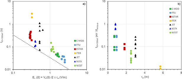
Figure 10. (a) The calculated time, a RE needs to achieve an energy of 10 MeV, tW = 10 MeV, using equation (14), and experimental values of E(t) versus the initially supplied external electric field, EL. The dashed line indicates the time, assuming a constant E(t) = EL(0). (b) The same data on tW = 10 MeV, normalized Δtramp-up ordered against the device major radius, ro.
Download figure:
Standard image High-resolution imageIn section 2, losses due to too large RE DO are introduced. This assumes that RE gain energy quickly, such that their DO, which depends on the plasma current, intersect with the vessel. However, during the tokamak start-up the current is increasing, and the question is, how the RE energy increase compares to this current rise? It should be reminded, that a related value of τRE is derived (equation (1) for a constant E and I, i.e. assuming these values do not change over the time the RE is accelerated and lost. It is, therefore, worth comparing the time scales to gain a certain energy (by free acceleration) and at what time DO for a specific RE energy are confined. The latter depends on the growth of the current, I, according to equation (10). Figure 11(a) compares tW = 10 MeV with the time by which the current is large enough to confine DO of RE with an energy of up to 10 MeV, at a location ro, tWDO = 10 MeV. It shows that in many cases these time scales are comparable and of the order of Δtramp-up. And thus the assumption that I and E are constant is not satisfied.
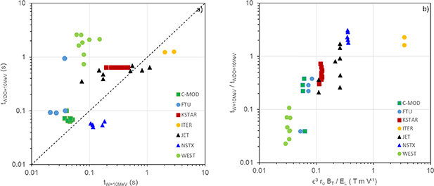
Figure 11. The time to reach a current large enough to confine RE DO with an energy of WRE = 10 MeV, tWDO = 10 MeV, is compared with the time needed to achieve this energy by free acceleration in E(t), i.e. tW = 10 MeV. (b) The ratio of these two times are shown, versus a scaling parameter that depends on ε (inverse aspect ratio), a, ro, BT and the loop voltage at the start of the discharge, VL(0).
Download figure:
Standard image High-resolution imageIf tWDO < tW, it means the current needed to confine the RE DO increased faster than the fastest (i.e. free) possible acceleration of the RE. Whether DO are possible is determined by the ratio of the maximum energy for which DO are confined, γDO(t) for a given value of I(t), to the maximum value of the energy that could be achieved by free acceleration in a field E(t), γmax(t). It is usually assumed that at very low plasma currents DO losses are easiest, however, before the creation of CFS the maximum electron energy is limited. Thus in general, DO losses only become possible after the creation of CFS while also enough time should have passed for the electron energy (γmax(t)) to increase such that γDO(t)/γmax(t) reduces below unity. For many discharges in the database, γDO(t)/γmax(t) starts above unity, but as the electron energy increases, it eventually decreases below unity and DO become possible. This is true for all cases in figure 11(a), for which tWDO = 10 MeV < tW = 10 MeV (i.e. for WEST, KSTAR, C-MOD and FTU and partly JET). However, for those that have tWDO = 10 MeV > tW = 10 MeV the ratio of γDO(t)/γmax(t) remains above unity during the entire current ramp-up, and thus DO will never be possible (i.e. for NSTX, ITER and some JET cases).
Figure 11(a) shows a big variation per device. The difference here lies in that the current, a device operates at, scales as ε2⋅ro⋅BT, where ε is the inverse aspect ratio of the device and the loop voltage it applies. The geometric factor in equation (10) also depends on ε, thus tokamaks that operate at higher currents and have larger inverse aspect ratios, are able to confine RE drift orbits more easily, i.e. have a shorter tWDO = 10 MW. While devices that operate at a higher VL will quicker accelerate RE and thus have a shorter tW = 10 MW. Figure 11(b) shows the scaling of the ratio of tW = 10 MW and tWDO = 10 MeV with an arbitrary scaling using these parameters. This of course does not capture the exact temporal dynamics of E(t) and I(t), but, nevertheless, explains the differences per device. For a larger device such as ITER, operating at a large plasma current but with a small loop voltage, RE DO are unlikely to be possible. The same is true for smaller devices but with a larger aspect ratio, such as NSTX. The selected JET cases, for this study, have a rather low VL (see figure 1(a)) and for some JET cases, the ratio is above unity and thus DO losses are unlikely while for others, like C-MOD, FTU and KSTAR such losses are possible. This means that RE DO losses cannot be considered a standard and common RE loss mechanism. Such losses are only possible under specific circumstances and in smaller, lower aspect ratio devices.
4.5. Cases with an increasing ξ
In section 4.1 it was described that in general, the streaming parameter ξ decreases as a function of time, from a non-thermal situation at the time of plasma initiation, usually thermalizing about 10% into the current ramp-up. As noted in section 2, a high streaming factor means a non-thermal plasma, thus the energy distribution being non-thermal and this is not necessarily equivalent to the presence of RE. Many cases that show clear signs of RE have at the same time ξ < 0.065, suggesting that the plasma is to be considered predominantly thermal, though likely a small amount of RE are still detectable. As reported in section 3.1, a typical JET discharge with a low streaming parameter (ξ ≪ 0.065), though exhibiting small but measurable signs of start-up RE, would have a RE current that was only a few % of the total current.
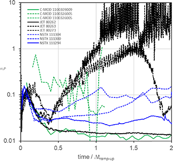
However, figures 2–4, show several cases for which ξ starts to increase again and these are shown together in figure 12. Note that this figure also shows a comparable case for each device that shows normal thermalization. The higher value ξ (i.e. ξ > 0.1) at a larger current (later in the current ramp-up) is an indication that a larger fraction of the current is carried by RE. The streaming parameter, as given by equation (1), can be split into a thermal (ξTH) and a RE (ξRE) part, and, assuming that ξTH ≪ ξ, be approximated as:
Figure 12. The temporal behaviour of the streaming parameter, ξ, for several specific cases from the database, showing it to slowly increase during the current ramp-up. The time bases have been normalised such that the different devices can be compared, for which more than only the current ramp-up is shown. The cases that develop large values of ξ are shown dashed, while for each device, for comparison, also a case shown that thermalizes in a normal fashion. In comparison for each of the three devices, also a standard case is shown, for which the ξ decreases after the plasma initiation, and stays low and constant.
Download figure:
Standard image High-resolution image
Thus showing the streaming parameter becoming proportional to the fraction of RE. It is important to realize that the RE density nRE≪ ne, and even discharges with a current fully carried by RE (i.e. IRE ∼ I), would have nRE ∼ 1015 m−3 compared to a cold background thermal plasma with ne ∼ 1018 m−3 [5].
The specific NSTX and JET cases show the typical higher ξ at plasma initiation that initially drops (thermalization), followed by a reversal at approximately a quarter of the current ramp-up, after which ξ increases steadily. Based on the available Te data, although not always accurate, it is possible to estimate that all these cases with ξ > 0.1 also have a high fraction of the total current carried by RE. Thus the behaviour of these discharges is dominated by the RE and assumptions of for example Spitzer resistivity do not apply at this time anymore. The reason for this transition is that all these cases develop low values of ne/j. This is purposely done for the NSTX cases, ramping down the density to generate RE for scientific purposes. Importantly, the plasma initiation and early ramp-up for these cases, ensure a quick decrease in the early ξ, hence these NSTX cases are likely having a short primary drive, creating a smaller seed than would be possible if the early density was kept lower. The two JET cases face a control error causing an unwanted decay of the density. The increase in IRE also reduces the fraction of the thermal current and hence the Ohmic heating, usually yielding a collapse of the thermal plasma Te, reminiscent of a burn-through failure during plasma initiation [5]. The very low values of ne and Te, under these circumstances, make it difficult to accurately determine ξ.
The lowering of ne with respect to j, as is done for the NSTX cases, is generally known to be a scenario to enhance start-up RE. It is usually assumed that the reduction in ne lowers Ec, possibly ED and that this is sufficient to increase the RE generation. However, this process is less clear if one considered that lowering ne leads to a higher Te and thus a lower E as well. Thus, an increase in RE generation is not at all obvious, and especially not to take place on a time scale as shown here. A further point is that the role of RE losses or the RE confinement time in this process should not be underestimated. The balancing of RE generation and losses during the current ramp-up may be rather delicate. From the analysis in section 4.3, a rough indication of how the RE confinement scales from device to device was found. However, the RE loss process and how it scales in detail with tokamak discharge parameters, and thus how it may vary during the ramp-up, is not well understood. Another possibility is that the generation process itself is more complex than purely based on secondary generation given by equation (7), or possibly the seed created by the primary drive is larger than assumed here. The understanding of this process may require further study aided by self-consistent start-up simulations that include RE generation and losses.
Clearly, a dominating effect of RE on the discharge dynamics should be prevented. The formation of discharges with large values of ξ, and high fractions of IRE, are prone to cause damage when they are terminated and thus should be avoided. But such cases are rather rare, while most devices can detect many cases that show signs of RE, only a handful of cases are found to develop into discharges that are dominated by RE. Also that the formation process of a full RE beam during the tokamak start-up is rather slow (as can be seen in figure 12) because of the low values of E/ED (and E/Ec) during the development of these RE beams. For example, for the JET cases, this took about 1–2 s to complete. It is therefore perceived that this process is not a necessity, for start-up RE to be able to cause damage.
5. Summary and extrapolation to ITER
This study aimed to disentangle various aspects that are linked to the formation of RE during the early stages of a tokamak discharge, i.e. plasma initiation and the current ramp-up phase. The focus lies here primarily on the comparison of relevant time scales that are thought to relate to RE formation. Simply also because it is not possible to compare for example IRE, nRE, or WRE because such data is usually not determined for all discharges. If such data would exist, it would greatly improve the capability to compare start-up RE simulations directly with experimental results. Most RE detection methods vary per device and usually provide only a rather arbitrary indication of the presence of RE. The detection threshold may differ, and for one diagnostic, or at one specific device, RE may be detected earlier and easier. Therefore, this analysis purposely did not try to separate cases between those that have RE and those that do not have RE, because such separation is already arbitrary due to the diagnostic issue. Thus also the classification of cases 'with RE' and those 'without RE' is subjective and no further attempt was made to sort the data as such.
The paper has noted similarities and differences, between the generation of RE during the tokamak start-up or when the discharge disrupts. Although the same basic RE generation mechanisms are to be considered, the main differences lie in the dynamics of the key discharge parameters, with disruptive RE generation occurring in the presence of a fast decay in plasma energy and current, while the opposite is generally the case for the tokamak start-up. Furthermore, plasma conditions may differ, for example, on the electron density and impurity content, which in the case of disruptions is often dominated by the effects of disruption mitigation measures. While tokamak start-up concerns low electron densities and low-Z impurities (that originate from plasma-surface interactions during the plasma initiation process) [14]. The conditions after a disruption of an ITER high-performance discharge disruption, are such that one may also have to consider tritium β-decay and inverse Compton scattering as a primary source of RE [16]. However, the conditions after disruptions, which ensure that such effects are relevant, do not apply during the tokamak start-up. For example, the effect of Compton scattering on the RE seed depends on the total (free and bound) electron density, which is orders of magnitudes larger during disruptions, especially after mitigation by massive gas or shatter pellet injection, and also the gamma energy flux from the activated walls, is also substantially lower during the discharge start-up [16].
The conclusion from the analysis is that RE simply form in all tokamak discharges, only in some discharges more RE are generated such that they can be detected by the diagnostics. But this means, that it is not possible to set a threshold based on physics principles that determines RE are not generated. This is also independent of the value of EL or pn, which are often traditionally often quoted as key to start-up RE formation [4]. It is not the question if RE form during the tokamak start-up, but how many. Thus, assuming RE are present for all cases, those with and those without signs of RE, typical time scales related to the RE generation were compared. The study here shows, that tokamak discharge initiation results always in a non-thermal plasma, i.e. ξ > 0.1, though still at a low current. In general, discharges thermalize (i.e. ξ decreases to lower values well below 0.10 on a time-scale of the order of a tenth of Δtramp-up. The relationship between ξ and E/ED, tells us, that in this case Dreicer type or primary generation of RE will cease. Nevertheless, prior to this time, primary generation will create a RE seed in all tokamak discharges. A comparison of diagnostic thresholds showed that usually around this time, most tokamaks will be able to distinguish discharges that have a significant RE population. Differences are due to the dynamics of primarily ne, with respect to the current, but also Te. Those discharges that thermalize earlier will reduce ξ and E/ED faster and thus will have a shorter time during which primary generation is effective. Such cases will form a smaller RE population around about one-tenth into the current ramp-up. It also raises the question if such small RE seeds, during the current ramp-up phase, are capable to affect the development of the current density profile. The dynamics of start-up RE generation were studied making use, or comparing them to, the physics basis and equations, as presented in section 2.
After thermalization, the RE seed can be further amplified by secondary generation. It was shown that for all cases, secondary generation is possible during the entirety of the current ramp-up, i.e. E > Ec. The effectiveness of this second process depends on the value of E − Ec, but also τRE. It is common to see signals indicating the presence of RE decrease during the current ramp-up, indicating the secondary growth rate in these cases is not sufficient to compensate for the losses, leading to a reduction in the number of RE. Note, that even if a small seed is established, for example by ensuring an early thermalization during plasma initiation, secondary generation can be used to enhance this small seed to detectable levels. This again shows how difficult it is to separate 'cases with signs of RE' with respect to a physics operation space because the formation process could differ: (1) a longer, effective, early primary generation followed by moderate or less effective secondary generation, or (2) a shorter early primary generation followed by an effective secondary generation and finally a combination of both, likely the worst case scenario, (3) a slow thermalization and effective primary generation followed by a phase of effective secondary generation. Both the primary and secondary generation are active over considerable fractions of Δtramp-up and it is thus not easy to link relate RE characteristics to a specific discharge state/parameter at a fixed time, i.e. a ne, ne/j, EL/pn etc. Classification of start-up RE is better achieved by relating the observations to the dynamics of such processes, such as the typical time-scales that have been studied in this work.
The secondary enhancement of the RE seed was found to be reduced in larger devices. The higher Te, and thus lower resistivity, during the current ramp-up in larger devices, reduced E with respect to Ec. Simulated ITER current ramp-ups showed values of at least E < 2⋅Ec while E can even drop below Ec. This indicates, that independent of the value of τRE, the enhancement of the RE seed will not be as effective as in smaller devices or possibly even absent in ITER. Also keep in mind that for E < 2⋅Ec it is thought that the secondary growth rate might be lower than the value given by equation (7) [19–22].
Without a thorough knowledge of RE loss mechanisms (and τRE) is dynamics of RE during tokamak start-up cannot be fully understood and properly simulated. RE are very well confined and it was found that estimated values of τRE increased strongly with machine size (i.e. ro +2.57). It would suggest values of τRE of the order of at least tens of seconds to possibly hundreds of seconds during the ITER current ramp-up. But such time scales are still comparable with the RE generation rates, and hence, a different choice in the value of τRE could easily influence simulation results. RE losses during the early current ramp-up are often attributed to DO losses, however an analysis of the time needed for RE to increase their energy to high enough values for their DO to be exceeding the bounds of the vessel showed that such losses are difficult in the early stages of any tokamak. RE require time to increase their energy, after flux surfaces are closed, while the current is ramped up, i.e. DO are better and better confined. For smaller devices that operate at high EL, (i.e. the current is low, and the RE energy increase is fast) eventually, RE DO losses become possible, however, for devices that operate at lower EL and higher current, like ITER, this may never be the case. The question is what role DO losses play for RE confinement during the tokamak start-up? A better candidate loss mechanism seems to be due to diffusion due to magnetic micro-turbulence, though this could not be conclusively proven with the data studied here.
In the majority of the cases that showed signs of elevated levels of RE, it is suspected that the faction of current carried by RE is low (i.e. a few % only). An increasing streaming parameter, during the current ramp-up, is a good indicator of whether this fraction increases. Rarely, this fraction rises above 50%, which would mean that the discharge is dominated by the RE. Such cases are obviously prone to cause damage, and in JET discharges with 1 MA of RE current have been obtained [5]. The loss of such a RE beam obviously damaged in-vessel plasma-facing components. The conversion into such full RE beams is however slow, usually a large fraction of Δtramp-up, thus counter measures could be taken. In JET this process took approximately 1 s [5]. Unfortunately, operation experience indicates, that most damage due to the loss of start-up RE, is not from these rare occasions. A more likely scenario for start-up RE to cause damage, might be, that a significant seed of RE is created during plasma initiation and the current ramp-up, after which the tokamak discharge is terminated and the current is quenched, such that the RE seed is further enhanced. This could happen if the discharge disrupts during the current ramp-up but also if the current is quenched due to a burn-through failure during the plasma initiation process [5, 48].
It means that to avoid start-up RE damage, the RE seed formation should be minimized, and appropriate control actions should be taken to avoid further enhancing this RE seed. Ensuring a high ne is often seen as a measure to minimize RE generation during tokamak the start-up. However, for Ohmically heated plasmas, increasing ne, would reduce Te and thus enhance E. The study suggests that supporting the increase of ne and Te during the tokamak start-up, by applying auxiliary heating, is the most effective method of reducing the RE primary and secondary generation mechanism. This effect, however, will have to be balanced against the RE source provided by the ECH itself. RE generation mitigation measures require robust control over both ne and Te keeping them within bounds, ensuring a fast reduction of the streaming parameters. However, if these parameters cannot be kept within bounds, or if a too-large a RE seed is detected, the most appropriate action would be first to reduce the voltage on the tokamak poloidal field coils, i.e. basically setting VL = 0 for long enough such that the RE can dissipate). At ITER accurate detection of RE and IRE will be available from the start of ITER plasma operation (ITER First Plasma), with such nominal control and exceptions put in place to prevent and avoid start-up RE formation [63, 64].
The analysis presented here provides confidence that the time scales for RE generation for ITER of the order of seconds, hence, the control response does not necessarily have to be fast (i.e. milliseconds). However, simulations of RE generation and its interplay with plasma initiation and the current ramp-up dynamics should provide a more detailed view of the start-up RE behaviour in ITER. This experimental study can provide support to the development of more accurate start-up models and simulations that include RE generation.
Acknowledgments
The views and opinions expressed herein do not necessarily reflect those of the ITER Organization. This publication is provided for scientific purposes only. Its contents should not be considered as commitments from the ITER Organization as a nuclear operator in the frame of the licensing process. The KSTAR and Seoul National University research has been supported by R&D Program of 'R&D on Key Technology of ITER Components' through the Korea Institute of Fusion Energy (KFE) funded by the Ministry of Science and ICT of the Republic of Korea (No. KFE-IN2022-11). The NSTX work has been supported by US Dept. of Energy Contract DE-AC02-09CH11466. The C-Mod research was supported by US Dept. of Energy Award DE-SC0014264. The Universidad Carlos III de Madrid work is supported by the Project PID2019-110734RB-I00 (AEI, Spain), and from Comunidad de Madrid under the agreement with UC3M in the line of Excellence of University Professors (EPUC3M14). The JET work has been carried out within the framework of the EUROfusion Consortium, funded by the European Union via the Euratom Research and Training Programme (Grant Agreement Nos. 101052200 and 633053 EUROfusion) and from the RCUK Energy Programme (Grant Number EP/P012450/1). Views and opinions expressed are however those of the author(s) only and do not necessarily reflect those of the European Union or the European Commission. Neither the European Union nor the European Commission can be held responsible for them.