


Abstract
The paper reports a systematic assessment of the radiation-hard Hall probes (RHP) magnetic diagnostic system of the JET tokamak, which is based on InSb semiconductor thin films, and describes the path that lead to the proposal of an innovative magnetic probe concept. A relevant account of RHP operation during the recent deuterium–tritium experimental campaign is also provided, showing correct operation under ITER-like intense neutron flux. The period considered for the systematic assessment of the RHP system ranges from October 2009 to March 2021, during which the machine produced more than 19 000 pulses. The RHP system consists of six three-dimensional Hall probes, which have built-in recalibration capability, thanks to the presence of microsolenoids that produce a local known field during a tailored automatic pre-pulse calibration sequence, that can also be initiated manually. During pulses, the microsolenoids can also be used as inductive sensors as their signals are recorded as well. Moreover, the system provides temperature measurements at the location of the probes, which are continuously recorded too. The assessment demonstrates accurate long-term operation of the RHP system. All the diagnostic channels reliably provide pre-pulse calibration data and pulse signals and the original sensitivities of the Hall sensors are preserved. Integration considerations and a data fusion analysis lead to the proposal of a high performance, compact, broadband, hybrid field probe, consisting of the combination of an inductive coil and a Hall sensor, to be manufactured by means of the coil technology developed for ITER or an alternative concept with improved radiation-hardness. The hybrid probe is expected to deliver the advantages of both inductive and Hall sensing technologies, essentially in the same package size of a single ITER magnetic discrete probe. In particular, it would solve the problem of the drift of the integrator for long lasting burning plasma discharges. The signals produced by the coil and the Hall sensor, processed by means of a Luenberger–Kalman observer, provide a magnetic field measurement which is non-drifting and low-noise. For these reasons, the hybrid probe has been proposed as the potential primary magnetic diagnostic sensor for future burning plasma experiments and demonstration fusion power plants.
Export citation and abstract BibTeX RIS

Original content from this work may be used under the terms of the Creative Commons Attribution 4.0 licence. Any further distribution of this work must maintain attribution to the author(s) and the title of the work, journal citation and DOI.
1. Introduction
Magnetic diagnostics are essential components for the operation and understanding of fusion machines [1–5]. In particular, inductive magnetic discrete probes, or pick-up coils [6], are widely used to measure the local magnetic flux density B and are typically installed as arrays on the inner and on the outer skin of the vacuum vessel, forming poloidal and toroidal belts. Their primary function is to measure and control the current, position, shape and instabilities of the plasma. Pick-up coils provide a signal proportional to the time derivative of B, which therefore needs to be integrated in time. Unavoidable disturbing signals, present in the diagnostic chain (sensor + cabling + electronics) also get integrated. This results in a measurement error, referred to as the integrating or integrator drift problem. For currently operated machines, such as JET, the drift is essentially due to an offset signal originating in the electronic integrator of the data acquisition system [7, 8]. For the case of burning plasma experiments (BPXs) [9, 10], such as ITER, and for future demonstration power plants (DEMO), such as the European DEMO [4, 5], the drift problem is particularly challenging, for two reasons:
- in addition to the offset in the electronic integrator, another disturbing signal, which is essentially due to the effects of the nuclear radiation and thermal fields acting on sensors and cabling [9–21], and which gets integrated in time too, becomes particularly significant,
- the plasma discharge has comparatively much longer duration, imposing longer integration time.
Both these facts contribute to a resulting measurement error that can become unacceptably large and can lead to failure of the control action on the machine.
To overcome the drift problem of inductive coils, magnetic probes based on the Hall effect [22–28] can be considered, as they provide a direct measurement of B, not needing integration. Figure 1 illustrates the working principle of Hall probes, with reference to a sensing element represented by a slab, made of a n-type semiconductor [27] or a n-type metal [23–26], for which the dominant charge carriers are electrons (n-type materials). Hall sensors are typically based on a semiconductor sensing element rather than a metallic one, due to the much larger sensitivity of the former (see table 1). With reference to figure 1, if an electric current I is injected in the slab along the in-plane direction indicated, the charge carriers are subject to a force in the perpendicular in-plane direction which, according to the Lorentz force, is proportional to the component of B normal to the slab. The electrons are hence deflected and a negative charge accumulates on one side of the slab (and a corresponding positive one on the opposite side). This produces an in-plane electric field and hence a Hall voltage UH that can be measured with a voltmeter, as indicated. If q and n are respectively the charge and the concentration of the charge carriers and t is the thickness of the slab, a simple derivation provides [27, 28]
where  is the Hall coefficient for a n-type material (for a p-type semiconductor
  , where p is the charge concentration of the electron holes [27]) and
  is the Hall sensitivity.
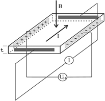
Figure 1. Illustration of the working principle of magnetic sensors based on the Hall effect [22–28].
Download figure:
Standard image High-resolution imageTable 1. Typical magnitudes of the Hall sensitivity SH for various sensing materials at room temperature. For the temperature dependence of many of the listed materials see [41].
| Material | Film thickness (nm) | Sensitivity at room temp.
|
|---|---|---|
| Graphene | 5 × 10² | |
| InSb | 1000 | 2 × 10 |
| InAs | 100 | 4 × 10 |
| Bismuth | 1200 | 3 × 10⁻¹ |
| Antimony | 900 | 2 × 10⁻² |
| Chromium | 50 | 4 × 10⁻³ |
| Doped diamond | 3600 | 10–3 |
| Gold | 50 | 10–3 |
| Molydenum | 190 | 9 × 10⁻⁴ |
| Molydenum | 750 | 2 × 10⁻⁴ |
| Tantalum | 750 | 10–4 |
| Copper | 800 | 7 × 10⁻⁵ |

The output voltage of an actual Hall sensor is perturbed by the presence of a spurious component Usp, which is due to Hall sensor manufacturing imperfections (such as misalignment of the sensing contacts or sensing layer inhomogeneities) and to the effect of the field component perpendicular to the one to be measured (planar Hall effect) [28]. Usp increases with the biasing current and the magnetic field and is temperature dependent. In addition, various radiation induced effects, acting along the whole diagnostic chain, introduce a further disturbing voltage Urad, characterized by a narrow, low frequency spectrum. The current spinning technique [28], which periodically interchanges the couple of terminals where the current is injected with the one where the voltage is measured, is used to reduce the spurious voltage Usp, in particular for metallic sensors, for which it is particularly relevant. Additionally, the current is modulated and synchronous detection allows to remove Urad and other disturbances [29].
Standard electronics is based on p–n junction physics, which is particularly susceptible to the action of ionizing radiation. On the contrary, the active element of a semiconductor Hall sensor is essentially a thin film of semiconductor material, non including p–n junctions, and hence its functionality is not impaired by radiation. However, since the Hall coefficient is inversely proportional to the charge carriers concentration n, which is increased by ionization, the sensitivity of a Hall sensor is reduced as an effect of radiation. Consequently, while the sensor still works under radiation, the accuracy of the measurement is altered. The legacy basic principle that consents to obtain radiation-resistant, or radiation-hard, Hall sensors is to use doped semiconductors, which have comparatively much larger charge carrier concentration. By doing so, the sensitivity gets reduced but its variations are minimized. There is hence a trade-off between sensitivity and stability and an optimal amount of doping is determined to achieve good performance. Optimal doping also conveys good thermal stability [30].
Radiation-hard Hall sensors capable to withstand fluence levels of current and next-generation fusion machines are not particularly relevant from an industrial standpoint. Consequently, only few products were and are to date commercially available, and their specifications do not match the required fluence and maximum survival temperature. Significant R&D was hence carried out in the last two decades to develop Hall sensors resistant to fusion environment [29–42].
Standard commercial Hall sensors based on silicon have poor resistance to nuclear radiation, as their electrophysical characteristics change already at neutron fluence of the order of 1013 cm−2. GaAs based sensors are more resistant, as their properties remain intact well beyond 1014 cm−2 [31]. Sensors based on GaN are also more resistant. As a general rule, the threshold for 'significant damage' to a radiation-hard semiconductor Hall sensor lies in the range 1016–1019 cm−2 [31]. Two notable semiconductors used to make radiation-hard Hall sensors are InSb and InAs. Sensors based on these were reported to remain stable up to neutron fluences of 2 × 1018 cm−2 [32] and about 1018 cm−2 [39], respectively. The radiation-hard Hall probes (RHP) magnetic diagnostic system of the JET machine, described in the next section, is based on InSb thin film Hall sensors.
Besides semiconductors, other materials can also be considered as sensitive elements of Hall probes. In particular, extensive R&D has been carried out in the last decade, and is ongoing, aimed at developing Hall sensors able to survive harsher conditions, corresponding to the ex-vessel and in-vessel environment of BPXs and DEMOs. The materials considered are in particular metals and carbon allotropes (doped diamond and graphene) [23–26, 35–42]. The main advantages of metals are in general resistance to much larger neutron fluence and capability to operate at high temperatures. Their main disadvantage is low sensitivity. Bismuth (Bi) constitute an exception since, on the contrary, has a relatively low melting point and features high sensitivity. While the latter property makes Bi attractive, the low melting point limits its use to selected applications (such as ex-vessel sensors). Hall sensors with antimony (Sb) sensing layer are recently being developed as a better option than Bi, for both ex-vessel and in-vessel application [40]. They feature much higher melting point, enhanced chemical stability, linear dependency UH(B) (implying easier and cheaper calibration) and, depending possibly on the specific application, may not require a thermocouple for temperature measurement. The drawbacks of Sb are medium sensitivity and higher transmutation rate, which however should not constitute critical issues. The ITER ex-vessel Hall probes, which were designed to be based on Bi only [38], may actually foresee Bi on some sectors and Sb on other sectors of the machine.
Table 1 reports typical magnitude values of the Hall sensitivity SH for various radiation-resistant sensing materials at room temperature. The temperature dependence of many of the listed materials is reported in [41]. Table 2 summarizes the types and main characteristics of Hall sensors used in JET, ITER and the candidates which are currently being studied for application in BPXs and DEMOs, as well as in tokamaks to be used as facility for testing diagnostic components. The types used on JET and ITER belong to systems installed at ex-vessel locations, for which the neutron fluence is comparatively very small and the temperature is limited. They are hence not suitable (with the exception of Sb) to be used in-vessel on BPXs and DEMOs and do not represent a feasible technological solution for diagnostic systems of prospective fusion machines. For these, Hall sensors based on specific metals or carbon will have to be used. However, the JET RHP diagnostic system, described in detail in the next section, possesses peculiarities that make it relevant for the future development of advanced diagnostics at the system level, as it will be discussed.
Table 2. Types and main characteristics of radiation-hard Hall sensors used in JET, ITER and candidates for prospective machines, as well as for tokamaks and fission reactors to be utilized as facilities for testing diagnostic components. Notice that, while the neutron fluence on JET is much smaller than that on ITER and DEMO (last table column), the neutron flux during D–T pulses is instead close to 1013 cm−2 s−1, namely the same order of magnitude that will be experienced by the magnetic sensors installed on the inner skin of the ITER vacuum vessel (see the end of section 3).
| Machine/machine type | Sensors location (ex/in-VV) | Sensors types/candidates | Sensors sensitivity | Sensors hardness up to neutron fluence (n cm− 2) | Machine neutron fluence specification (n cm− 2) |
|---|---|---|---|---|---|
| JET (RHP diagnostic system) | ex | InSb | High | 2 × 10¹⁸ | ≲1015 |
| ITER | ex | Bi; Sb | High; medium |
 ; ≫1020 ; ≫1020
| 1.3 × 10¹⁸ |
| DTT | ex/in | InAs (& Sb)/Sb, Cr | high/medium | 1018/≫1020
| 8 × 10¹⁶/2 × 1017 |
| DEMO, testing facility | in | C | High; medium; low | ≫1020
|

|
aGraphene (or doped diamond). bExtrapolation based on preliminary analyses and irradiation testing results. cDepending on the blanket type and on future technological improvements and design changes (see [5] for the present worst case).
The paper reports about three strictly related matters:
- (a)long term operation of the RHP magnetic diagnostic system of the JET tokamak, including correct operation under ITER-like intense neutron flux, achieved during recent deuterium–tritium (D–T) pulses;
- (b)data fusion experiments, based on signals produced by the RHP system;
- (c)the proposal of a hybrid magnetic probe, constituted of a combination of an inductive coil and an Hall sensor and built by means of enabling technologies, making it an ideal magnetic diagnostic component for BPXs and DEMOs.
As we shall see, points (b) and (c) are conceptually related. In fact, the RHP systems is equipped with microsolenoids, used as local magnetic field generators for in situ recalibration of the Hall sensors, which can however be used as pick-up coils as well. The characteristics of the proposed hybrid probe (c), which is being developed, are:
- it has capability to operate in harsh fusion environment under large neutron and gamma fluxes and fluences and relatively high temperature [20, 21];
- features broadband accurate measurement, achieved in particular by implementing a Kalman observer in the acquisition electronics;
- provides primary contributions to the measurement of plasma parameters [1, 15] (see section 5);
- it is comparatively small sized and simplifies engineering integration, with respect to the deployment of separate inductive and Hall sensor based subsystems.
These properties make the magnetic probe being proposed a very competitive candidate to be used in future fusion machines.
2. The RHP diagnostic system
The RHP magnetic diagnostic system was installed on JET in June 2009 [43] as part of the EP2 diagnostic enhancement programme, package III: improved profiles and detection & test of techniques. It is composed of two ex-vessel subsystems: RHP 5D lower outer probes and RHP 8D lower outer probes [33, 34, 43]. The former consists of three three-dimensional (3D) probes, three driver units (electronic boards), a dedicated mechanical supporting structure, which houses the probes, installed on octant 5 sector D (sector 5D for short, figure 2), a shielding metallic container, which houses the driver units, installed on sector 5E and three flexible cables, terminated by six LEMO connectors [33, 43]. Similarly, the RHP 8D lower outer probes subsystem consists of the same elements as the 5D subsystem. In particular, the mechanical supporting structure is installed on sector 8D, and the shielding box is installed on sector 8E. The only significant difference in octant 8 is a 50 mm downshift of the mechanical supporting structure, and hence of the sensors' vertical coordinates, with respect to octant 5. Such difference is consequence of a design feature, which was needed to leave a certain amount of freedom in positioning the support structure during the installation phase, because there were uncertainties regarding the internal geometrical configuration of the  mm hole in the shell of JET (figures 2(a) and (b)), in particular concerning the maximum height at which the probes could be installed. Since such shell is filled in with concrete, to act as the first neutron shield, during installation the assemblies were positioned as high as possible, so as to have the top probes exposed to the largest possible neutron flux, but not too high, in order to leave enough clearance distance from the vacuum vessel, to avoid damages during vessel movements/disruptions.
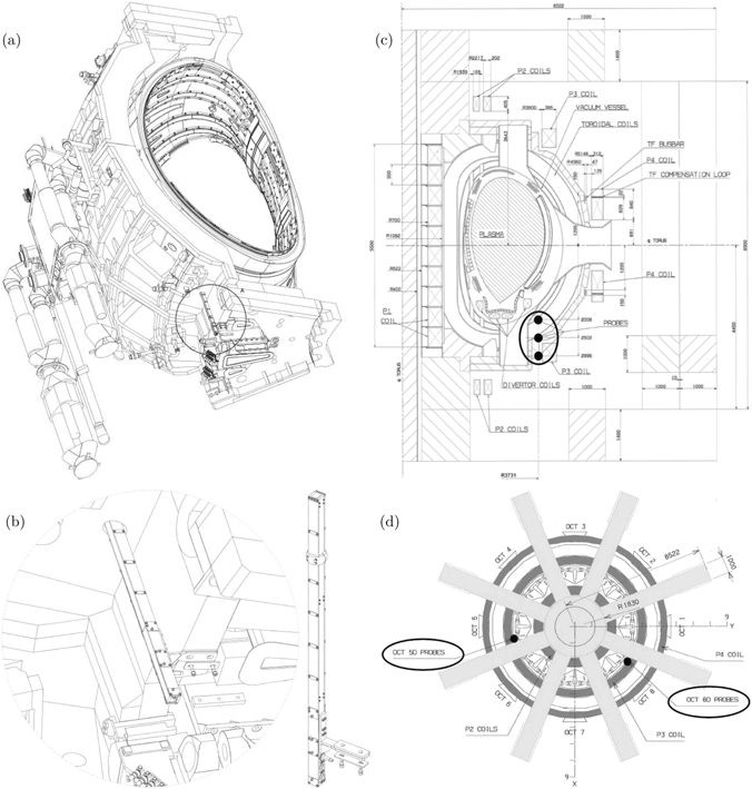
Figure 2. (a) CAD model of octant 5 of the JET machine. The model of octant 8 is almost identical. Not all the components are shown, in particular the poloidal field coil P3. (b) CAD model of the mechanical supporting structure of the probes, also showing that, as installed to the machine (at the lower outer part of sector 5D, circled in (a)), it is partly inserted in the  mm hole in the JET mechanical structure. (c) and (d) JET simplified cross-section and schematic plan view. The location of the 3D probes is represented by black dots. Their radial coordinate is approximately the same in both octants, while their vertical coordinates are slightly different. Specifically, sensors at octant 8 are about 50 mm lowered with respect the ones at octant 5 [33, 43]. The toroidal and poloidal field coils have a strong influence on the measured quantities. On the contrary, the TF busbars and TF compensation loops do not. In fact, they produce the field of two almost identical Helmholtz coils (associated to the odd and even TF coil sets), driven with opposite currents. Such a field has negligible effects at almost every location, which includes the RHP sensors.
Download figure:
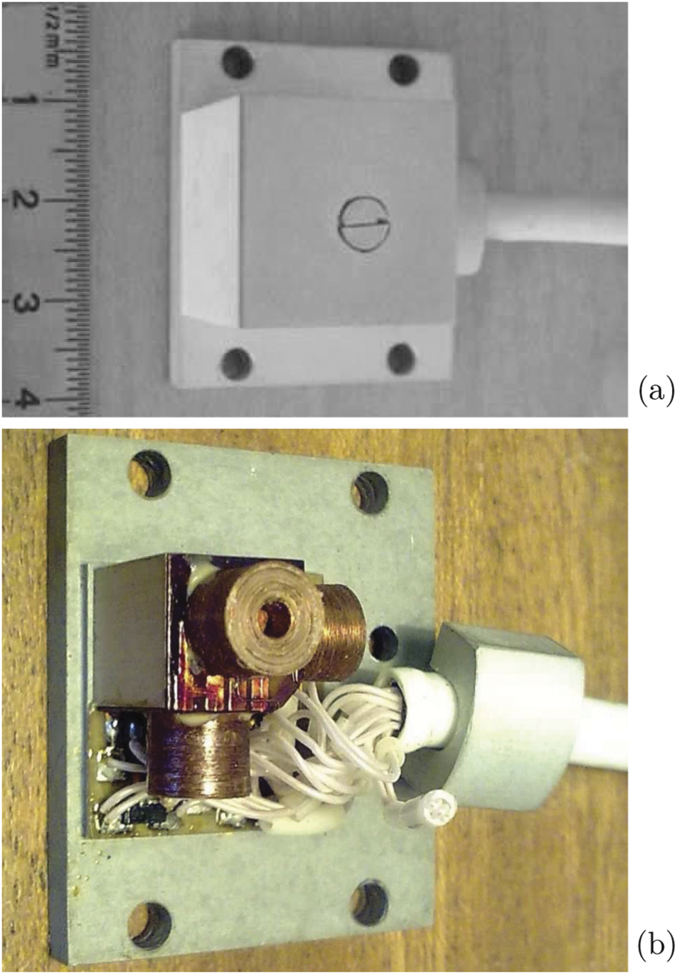
Standard image High-resolution imageEach 3D probe includes three Hall sensors, one thermo-diode and three small coils (figure 3). The Hall sensors were manufactured on the basis of InSb/i-GaAs semiconductor heterostructures. The active elements were formed on thin (1 μm) doped layers of InSb placed on semi-insulating substrates of GaAs (400 μm). There are in total 18 Hall sensors, six thermo-diodes and 18 coils.
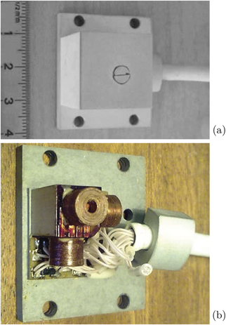
Figure 3. Overall (a) and internal (b) views of the 3D probe, consisting of three Hall sensors, one thermo-diode (the small chip in lower-left position in (b)) and three small coils. The latter are used to recalibrate the Hall sensors, by generating local fields of few mT (with a supply current of about 20 mA), but can also be used as pick-up coils. The side walls of the cover are made of Rubalit® ceramics (96% alumina), while the cover top and the baseplate are made of anodized aluminium. The volume occupied by the cover is that of a cube with side 20 mm. The thicknesses of the cover (side walls and top) and of the baseplate are 1 mm and 4 mm, respectively. The overall probe dimension is 35 × 30 × 24 mm3.
Download figure:
Standard image High-resolution imageEach Hall sensor was calibrated on bench in advance of installation on JET, so that the correspondence between the generated voltage and the field strength being measured is known. Besides that, the whole system has built-in, or in situ, re-calibration capability [33, 34, 43], which is based on a calibration sequence that is automatically run before each pulse, and can also be initiated offline (calibration mode) [44]. During the calibration sequence, which takes advantage of synchronous detection to reduce noise, an alternating current of about 20 mA flows in the coils, that so act as field generators (with magnitude of few mT), and the voltages produced by the Hall sensors, the calibration data VHj (n), are recorded. Here, j ∈ {1, ..., 18} denote a specific sensor and n is the JET pulse number (JPN). The first relevant JPN is n0 = 79 687 of 16 October 2009, which corresponds to the end of the functional commissioning of the RHP system [43, 44]. In case of degradation of the characteristics of the jth Hall sensor, which could arise after a certain amount of operating time, VHj (n) would sensibly change with respect to the original value VHj (n0). The factor cj = VHj (n0)/VHj (n) would then be used to recalibrate the measurement data produced during pulses (measure mode). However, as we shall see, the calibration data have not appreciably changed, for a long period of time (2009–2021).
One further feature characterizes the RHP system, which consists of the fact that, as a general monitoring provision to the machine, the temperature signals, besides being recorded during the calibration sequence and during pulses, are also continuously recorded [44].
The main function of the coils concerns the self-calibration capability of the system in calibration mode, but they can also be used as pick-up coils in measure mode. However, the coils were designed to monitor the changes of the sensitivity of the Hall sensors and not to accurately measure the magnetic field. Therefore they were not made to be very precise and identical, and thus their dimensions may vary. In fact, while the system was overall calibrated on bench, the coils themselves were not, so their magnetic sections NA [6] are not available. However, the coil signals were included in the set of data to be recorded as JET pulse files (JPFs), as that implies the availability of inductive measurements at the same location and direction of those provided by the Hall sensors. The coil signals are recorded in both integrated and non-integrated forms. The latter are particularly useful when used in combination with the corresponding Hall measurements, as that allows to obtain enhanced measurement performance by provision of data fusion capabilities in the acquisition electronics, as discussed in section 4. An approximate NA value can be obtained from the following estimated coils characteristics [44]: height 5 ± 0.2 mm, inner winding diameter 2 ± 0.1 mm, outer winding diameter 6 ± 0.2 mm, total wire diameter 0.1 mm (copper 0.08 mm, enamel 0.02 mm), total number of turns 825 ± 25, number of layers 20 (turns are distributed proportionally by layers). One then gets NA ≅ 0.011 m2. This value, although not particularly large (bigger values are normally chosen for equilibrium coils [18, 45, 46] to achieve effective signal-to-noise ratio), indeed provides sensible experimental results.
As stated in the introduction, in order to be applied to future fusion machines, characterized by much harsher nuclear environments, the research on Hall sensor based measurement has evolved by considering different types of sensing elements, most of which have much lower sensitivity SH than the one of the RHP. The concept represented by the RHP probe (figure 3), where a local solenoid surround a Hall sensor and is able to produce a suitable magnetic field for recalibration purposes, is then not applicable any longer. In fact, due to the significantly smaller SH value, the required current would be too high. The recalibration capability concept present in the RHP system was hence abandoned (in situ recalibration of the Hall sensor sensitivity against the coil would still be possible though, see section 5). However, we propose to reconsider the concept of a magnetic probe, constituted by the combination of a coil and a Hall sensor, not for recalibration purposes, but as an advanced probe concept, that will be described in the next sections.
From JPN 79687 (corresponding to the end of the functional commissioning of the RHP system, as stated) all sensors have been providing useful signals, which are stored in CODAS (control and data acquisition systems) and included in the JPF set. This situation remains unchanged at present time, showing the long-term reliability of the diagnostic system, which also includes correct operation under ITER-like intense neutron flux (see the last part of next section), achieved during recent deuterium–tritium (D–T) pulses.
The JPF channels are post processed to get quantities expressed in physical SI units, which correspond to the expected (temperature and) field values.
We should mention that, besides RHP, in JET there are other diagnostic components, in particular the collar probe, which makes available inductive and non-integrated (Hall) magnetic field measurements, approximately at the same location and orientation. However, due to a peculiar and unexpected non-uniformity of the field map local to the collar probe [46], it was not possible to exploit its data fusion potential. Even though such non-uniformity issue can be considered accidental and not very likely to arise in general, it is worth to keep it in mind for new designs.
3. RHP long term operation
The operation of the RHP diagnostic system was systematically assessed with reference to a period of over eleven years, from JPN 79687 of October 2009 until JPN 98803 of March 2021 (in addition, even more recent pulses were considered, as reported further below). That amounts to a gross total of 19117 pulses of the machine. Of these, only 17601 were selected for the analysis, the remaining being unsuitable as corresponding to hardware commissioning of components of the JET machine, CODAS test sessions/rehearsals, general hardware errors or general signals recording errors. In turn, the suitable pulses were further scrutinized by means of an automated procedure to remove aborted pulses and pulses for which specific signals of the RHP systems were not correctly recorded (either in measure mode or in calibration mode), leaving a net total of 15473 useful pulses. That correspond to an overall 19% lost pulses, only a limited part of which specifically consists of RHP data loss. In particular, due to an issue originated during a general CODAS maintenance activity, for a continuous range of 1290 pulses (from JPN 93213 to JPN 94502, included), corresponding to 6.7% of the gross total, the RHP calibration data were not correctly recorded. In this respect it should be noted that the RHP system is not defined to be an essential diagnostic, without which the machine could not be run. Thus, the procedures to ensure that it is restarted after a failure were not sufficiently robust. This issue was raised within CODAS, which then established a process to avoid/limit possible future data loss [47].
Figures 4(a)–(c) shows pre-pulse data for in situ calibration, corresponding to the mentioned period 2009–2021. In particular, the data (temperature, Hall voltage and distribution) relative to one of the Hall sensors (the 53V, providing the vertical field at the lower position in sector 5D, figure 2) are reported as an example, the others being similar. The distribution of the calibration data corresponding to the whole set of Hall sensors is also shown (figure 4(d)). The darker plot and histograms of figures 4(b)–(d) are obtained by compensating for the temperature dependence of the sensor's sensitivities. That is done by considering, for each signal, the compensated quantity  , where the overbar denotes the mean value, VH is the Hall voltage, T is the temperature,
  and the b coefficients result from linear regression analyses of the function VH(ΔT). For both the cases of the distribution corresponding to a single signal (figure 4(c)) and the one corresponding to the whole signals set (figure 4(d)), the standard deviation is about ±0.1% and ±0.07% respectively, when referred to the uncompensated and to the compensated quantities.
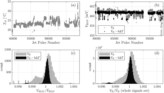
Figure 4. Pre-pulse calibration data relative to the JPN range 79687–98803 (October 2009 to March 2021). (a) and (b) Temperature (a) and Hall voltage calibration readings corresponding to the vertical field (b), at the location of probe 53. (c) and (d) Distribution of the calibration data, corresponding to the vertical field of probe 53 (c) and to the whole set of RHP Hall sensors (d). The darker plot and histograms in panels (b)–(d) are obtained by compensating for the temperature dependence of the sensor's sensitivities. For both the cases of the distribution corresponding to a single signal (c) and the one corresponding to the whole signals set (d), the standard deviation is about ±0.1% and ±0.07% respectively, when referred to the uncompensated and to the compensated quantities.
Download figure:
Standard image High-resolution imageThe system also reliably produce data in measure mode, as represented for instance in figure 5 with reference to JPN 99971 of 22 December 2021. This is a record D–T pulse of the recent DTE2 experimental campaign, during which 59 MJ of heat energy from fusion was produced for the first time [48]. We recall for reference that the DTE2 campaign started on 13 August 2021, with pulse 99329. Plots in the top row of figure 5 show the currents flowing in the circuits that power the JET machine [46], while plots in the other rows show the measurements provided by RHP system (black lines for sector 5D and gray lines for sector 8D). Specifically, lines labeled as Tnm and BHnmX respectively represent the temperature and the magnetic flux measurement provided by the Hall sensors, where n = 5, 8 specify the octant, m = 1, 2, 3 the top, middle and lower probe and X = T, V, R refer to the toroidal, vertical and radial directions. The radial coordinate of the sensors are approximately the same in both octants, while their vertical coordinates are slightly different. Specifically, as stated, sensors at octant 8 are about 50 mm lowered with respect the ones at octant 5 [33, 43]. That implies a different collocation of the probes with respect to the toroidal and poloidal field coils (figure 2) and hence different measured amplitudes in the two octants. In particular, the top probes (one per octant) measure a strong toroidal field (and stronger in octant 5). Due to the discrete nature of the odd and even toroidal field solenoids, consecutive coils in each set are connected by means of TF busbars. The resulting toroidal currents are compensated with two TF compensation loops, which are part of the P4 poloidal field coils. As it can be desumed from figure 2(c), the TF busbars and TF compensation loops produce the field of 2 almost identical Helmholtz coils driven with opposite currents. Such a field has negligible effects at almost every location. In particular, the effect is not relevant for the RHP sensors [43].

Figure 5. Signals produced by the RHP system during D–T pulse 99971 of 21 December 2021. This is a record pulse, during which 59 MJ of heat energy from fusion was produced for the first time [48]. Plots in the top row show the currents flowing in the circuits that power the machine [46] and the plasma current, while plots in the other rows show the measurements provided by the RHP system (black lines for sector 5D and gray lines for sector 8D). Specifically, the lines labeled as Tnm and BHnmX respectively represent the temperature and the magnetic flux density measurement provided by the Hall sensors, where n = 5, 8 specify the octant, m = 1, 2, 3 the top, middle and lower probe and X = T, V, R refer to the toroidal, vertical and radial directions.
Download figure:
Standard image High-resolution imageThe above assessment demonstrates accurate long term operation of the RHP system. All the diagnostic channels reliably provide pre-pulse calibration data and pulse signals. The original sensitivities of the Hall sensors are preserved, a result largely expected for semiconductor sensors containing indium [33, 34]. In fact, as we can see from table 2, the Hall sensors used in the RHP diagnostic would be stable up to a neutron fluence which is three order of magnitude larger than what achievable on JET (plots showing the degradation of the sensitivity with accumulated fluence are reported in [34]). Hence, while the demonstrated long term operation is an important milestone, clearly it could not be meant to confirm the radiation hardness, in terms of neutron fleunce limit, of InSb sensors under fusion spectrum. What is instead demonstrated here, which was a relevant motivation that lead to the proposal of the RHP project, is correct operation under intense neutron flux. For the most exposed sensors (those housed in the top probes, 51 and 81), such flux is, for D–T pulses, close to 1013 cm−2 s−1, namely the same order of magnitude that will be experienced by the magnetic sensors installed on the inner skin of the ITER vacuum vessel (behind the blanket modules) [11].
4. RHP data fusion experiments
As stated in section 2, the main function of the coils (figure 3) concerns the self-calibration capability of the RHP system. They were designed to monitor the changes of the sensitivity of the Hall sensors and not to measure the magnetic field. Therefore they were not made to be very precise and identical and were not calibrated on bench. Although their characteristics (magnetic section, magnetic axis [6]) are, hence, not available, the RHP project decided to acquire the signals produced by the coils in measure mode as well, in order to have the possibility of using inductive sensors located at those positions, to be used for future activities, in particular for general and local data fusion studies. By local data fusion we mean here the possibility of combining the signals provided by an Hall sensor and a coil positioned and aligned so as to measure the same field component at the same spatial location. Such a configuration is available in the RHP system, and we shall refer to is as hybrid sensor or hybrid probe. Figure 6 shows a simplified model of the hybrid probe and the way the data fusion concept is applied. The models of the Hall sensor and of the pick-up coil correspond to eqs. BH = B + dH and  , respectively, where B is the field to be measured, dH and dc are disturbances, here considered unspecified (they represent in general various sources of measurement error [1, 6–19, 49]), BH and
  are the raw output signals and the overdot means time derivative. We rewrite them in the form of the dynamical system

for which the input variables are the signals  , dH, dc, the output is BH and the state variable is B. An estimation Bo of the state B can be obtained by means of a Luenberger–Kalman observer, which can be written in the form

where ωo is a discriminating angular frequency characteristic of the observer. The estimation error e = Bo − B similarly satisfies
In the frequency domain, the model of the observer reads as
where s = iω. The corresponding error
remains limited at low frequencies. On the contrary, in the case of a legacy inductive diagnostic measurement, where an integrator processes the signal produced by the pick-up coil, the error would not be limited, being in such case (see figure 6)

implying a large error at low frequencies. As anticipated in the introduction, such error is referred to as the integrating or integrator drift problem, as it corresponds, in the time domain, to the integration of the disturbing signals dc and/or di. For currently operated machines, such as JET, the drift is essentially due to the offset signal di originating in the electronic integrator of the data acquisition system [7, 8]. For BPXs and DEMOs, the drift problem is particularly challenging, for two reasons: (i) the plasma discharge has comparatively much longer duration and (ii) the disturbing signal dc becomes significant, as it essentially represents the effects of the nuclear radiation and thermal fields acting on sensors and cabling [9–21]. Both these facts contribute to a resulting large drift error.
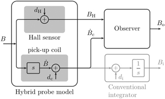
Figure 6. The data fusion concept applied to the hybrid probe. The box in gray color represents the traditional method to process signals produced by inductive sensors.
Download figure:
Standard image High-resolution imageAs equation (3) shows, the hybrid probe concept does not suffer of the drift problem (ω ≪ ωo), and filters out disturbing contributions at high frequency (ω ≫ ωo). These particularly relevant features of the hybrid probe can be experimentally verified by considering data provided by the RHP system. Figure 7 reports the result of such type of experiments. Specifically, in figures 7(a) and (b), the JET dry discharge 94814, and in particular the experimental data produced (in measure mode) by the two Hall sensors 53V nd 53R, and corresponding coils, have been analysed. The observer model (1) has been applied to the data, which exploits both the Hall and coil outputs (the latter non-integrated) and provides an improved measurement. The flux density B obtained by using the Hall data alone, the integrated coil data alone and the observer output are shown. For the case of the signal 53V, the problem caused by an offset at the input of the integrator applied to the coil signal is particularly apparent. For signal 53R, a high frequency component in the signal provided by the Hall sensor is visible. Clearly, the Luenberger–Kalman filter is capable of solving both these issues. Similarly, the correct action of the observer is also reported, in figures 7(c) and (d), for D–T pulse 99971, with reference to the vertical field of probes 51 (the most exposed to the neutron flux) and 82.

Figure 7. (a) and (b) Vertical and radial field, as measured by the Hall sensors and by the coils of probe 53, and as estimated by the Luenberger–Kalman observer (data fusion), for dry run 94814. (c) and (d) Cases of the vertical field of probes 51 and 82, for the D–T pulse 99971. The parameter of the observer is f0 = 5 Hz.
Download figure:
Standard image High-resolution image
As anticipated in section 2, the signal-to-noise ratio of the RHP coils is not optimal. Also, the accuracy of their angular orientation was not specifically controlled. That imply a significant noise pick-up, which is indeed the case, as the large drifts seen in figures 7(b) and (d) suggest. The non-optimal characteristics of the RHP coils were hence actually especially good, to show how effective is the data fusion concept in terms of removing the drift, which will be particularly valuable for the case of long-lasting discharges of BPXs and DEMOs (in which case the drift will have other major sources, as discussed).
The value we used as discriminating frequency of the observer, which produces the results shown in figure 7, is f0 = ω0/2π = 5 Hz. Such value, which is not critical (f0 in the range 5–20 Hz provides essentially the same results), is compatible with the frequency response of advanced Hall sensor based magnetic diagnostics, which are being developed for future fusion machines, for both ex-vessel and in-vessel use [35–37, 39–42].
It is worth to notice that here we considered only very simple models, for both the Hall and the inductive diagnostic chains. More complex models can be used to fit the design of the observer in the optimal Kalman filter theory.
5. High performance hybrid magnetic sensors
The above results suggest the adoption of the hybrid probe concept for designing magnetic diagnostic systems of future fusion machines, or to upgrade existing ones. This applies to ex-vessel systems, but also, and more importantly, to in-vessel ones. That would in fact improve the control capabilities of long-lasting discharges of BPXs and DEMOs [4, 5]. During the last four decades, significant investments lead to the development of materials and components, and in particular of inductive magnetic sensors [9–21, 50–55], capable to withstand the particularly harsh environment present at in-vessel locations. Specifically, the current state of art for in-vessel radiation-hard magnetic field measurement is represented by the LTCC (low temperature cofired ceramic [56]) pick-up coil technology developed for ITER [17, 18, 54, 55]. Integration and data fusion considerations lead to the proposal of a possible improvement of such technology [57]. In line with the above discussion, this would be a high performance, broadband, compact hybrid field probe, consisting of the combination of a radiation-hard inductive coil and a radiation-hard Hall sensor, housed in the same package. For instance, both sensors may constitute a unique ceramic element (made with LTCC or possibly other technologies, mentioned further below) or, more likely, they may be coaxial/stacked next to each other. The Hall sensor can be realised with a radiation-hard semiconductor (for the case of ex-vessel applications) or, as more extensively reported in the introduction, one of the promising alternatives which use selected metals, or graphene, or doped diamond, in place of the semiconductor [35–37, 39–42]. A relevant point concerns the classification of diagnostics in terms of the contribution they provide to specific measurement parameters, as follows [1, 15]:
- primary contributions: the diagnostic is well suited to the measurement;
- backup contributions: the diagnostic provide similar data to primary, but has some limitations;
- supplementary contributions: the diagnostic validates the measurement and/or calibrates the measurement and/or supplies only a part of the measurement requirements.
Thanks to the non-drifting property, a measurement system based on the hybrid probe would be a primary diagnostic system (e.g. for the measurement of the plasma current and shape) for BPXs and DEMOs.
For ITER, EU-DEMO and other nuclear fusion machines in general, different magnetic diagnostic systems are currently foreseen for different magnetic sensing technologies, each of which requires dedicated mechanical supporting structures, that occupy space. Besides the desirable properties discussed above, another consideration regarding the proposed hybrid sensor concerns then an integration concept. That is, as Hall sensors are small when compared to LTCC coils, the hybrid sensor has the advantage of delivering two different technologies, approximately in the same package size.
Other advantages of the hybrid sensor concept are local redundancy and the possibility of in situ recalibration of the Hall sensor sensitivity against the coil. Such recalibration can be either done actively, as in the case of the RHP system, or passively, by exploiting standard dry runs of the machine, dedicated dry runs and plasma pulses [58] and the plasma ramp-up phase, and/or by using simulators based on trusted sensor sets [59, 60]. A further aspect concerns the possibility of having combined sensors measuring two or three components of the magnetic field in a single probe. The probes of the RHP system are indeed triaxial (figure 3). Radiation-hard 3D coils constituting a unique ceramic element were indeed developed [50]. However, additional studies and experimental assessments, including irradiation testing, are needed to assess their operation in the harsh environment of BPXs and DEMOs, as issues are expected to arise (e.g. radiation and thermal non-uniformities and gradients, cross-radiation induced effects, possible difficulties in optimising compensating ground plates and/or corresponding cross-interference, reliability of the terminals). A likely better option would foresee an optimized integration, within a unique probe platform, of individual hybrid sensors each measuring a different field component.
Various technologies are worth to be considered for manufacturing magnetic probes for fusion machines. Cofired ceramic is a packaging technology mainly used for manufacturing ceramic electronic circuit boards. It comes in the two flavors LTCC and HTCC, where LT/HT stands for low/high firing temperature [less than about 1000 °C/(significantly) more]. The latter has a number of advantages in a wide range of industrial applications. While LTCC coils have been extensively tested in the nuclear fusion context, the same does not hold for HTCC coils, for which more limited testing was carried out [50, 52, 61]. HTCC coils are rugged, have solid connectors, posing no problems in connecting and mounting them, and were reported to be potentially superior to LTCC [52].
Another promising technology is TPC (thick print copper film), for which are reported, among other properties, a comparatively good thermal conductivity, multilayer circuit capability, sufficient adhesion of copper to alumina and aluminum nitride substrates and resistance to thermal shock cycling [61, 62].
An assessment of pros and cons of LTCC vs HTCC vs TPC is planned as a future activity. Also worth to notice is that the legacy coils technology for which the conductor (not necessarily a mineral insulated cable) is wound on metallic formers, can exhibit subtle non-linearities, sensibly affecting their calibration [45]. Coils wound on (i) ceramic formers or (ii) ceramic substrates (LTCC/HTCC/TPC) do not suffer of that problem. As an example of the first category, the high frequency coils developed for ITER deserve to be mentioned [63], a concept that may well be adopted for other purposes too.
The hybrid probe concept is being developed and will be tested for qualification in various testing facilities, including fission research reactors and possibly upcoming fusion machines too, such as the divertor test tokamak facility (DTT) [64] and the COMPASS Upgrade tokamak [65].
We finally remark that, in general terms, the idea of a combined coil-Hall probe is not entirely new. Besides RHP, the collar probe, mentioned in section 2, was installed on JET in 2005. Such probe was specifically intended for local data fusion too, but unfortunately it did not succeed in that purpose (see [46] and references therein). The novelty of our proposal consists of conceiving the combined probe for in-vessel measurements, by using the leading LTCC (or HTCC/TPC) fusion measurement technology, with the many consequent reported advantages, in particular in terms of control performances and integration. Pioneering patent regarding combined sensors for in situ calibration of the Hall sensor were issued in 2009 and 2010 [66, 67].
6. Conclusions
This work provides relevant contributions to the field of magnetic diagnostics in term of experimental results, as well as from a prospective standpoint. It reports an assessment of the RHP diagnostic system of the JET machine and an experimentally supported data fusion analysis. That naturally led to the proposal of a high performance magnetic probe concept for prospective fusion machines, along with technological considerations.
The RHP system provides pre-pulse data and pulse signals. The pre-pulse information is recorded for the purpose of in situ recalibration of the Hall measurements. This is achieved by generating modulated local magnetic field by means of microsolenoids present in the probes. The long term reliability of the system is established, across a period that spans over 11 years and comprises more than 19 000 pulses. This is an important milestone and, up to the authors' knowledge, it is the only result of this kind in the fusion context concerning radiation-resistant Hall sensors. In particular, all diagnostic channels reliably provide pre-pulse data and pulse signals. A characterization analysis, which consider the whole calibration data set shows that, for both the cases of distribution corresponding to a single signal or the one corresponding to the whole signals set, the standard deviation is about ±0.07%. The original sensitivities of the Hall sensors are preserved, a result largely expected for semiconductor sensors containing indium and specifically designed doping impurities concentration. In fact, the Hall sensor type used in the RHP diagnostic would be stable up to a neutron fluence which is much larger than what achievable on JET.
Another particularly relevant aspect shown in the paper is correct operation under intense neutron flux. For the most exposed sensors the maximum flux is, for D–T pulses, close to 1013 cm−2 s−1, namely the same that will be experienced by the magnetic sensors installed on the inner skin of the ITER vacuum vessel.
The microsolenoid present in the RHP probes can also be used to provide inductive measurements, at the same location and orientation of the Hall sensors. The RHP system makes hence available hybrid probes, each comprising a Hall sensor and a pick-up coil. That allows to perform local data fusion experiments. By using a suitably tuned Luenberger–Kalman observer, we could then show that the hybrid probe can provide a low-noise and non-drifting measurement. The latter property would be particularly relevant for effectively controlling long-lasting discharges of prospective fusion machines. To achieve that, we propose the adoption of the hybrid probe, as primary magnetic diagnostic sensor, for in-vessel application in BPXs and future demonstration power plants. That implies technological challenges, which are addressed by assuming to manufacture such probes by means of the LTCC coil technology developed for ITER or an improvement of that concept. Such approach would deliver the advantages of both inductive and Hall sensing technologies, essentially in the same package size of a single ITER LTCC probe, thus effectively contributing to the complex problem of in-vessel diagnostic systems integration too.
The hybrid probe concept is currently being developed and will be tested for qualification in various testing facilities, including fission research reactors and possibly upcoming fusion machines too, such as the DTT facility and the COMPASS Upgrade tokamak.
Acknowledgments
The authors would like to thank JOC for the assistance during the implementation of the RHP project, the installation phase and for the maintenance of the diagnostic. The authors wish to thank in particular S. Gerasimov, K. Fullard, A. Horton, A. Stephen, J. Farthing, P. Beaumont, W. Studholme, J. Conboy, C. Marren, P. Carman, P. Reid, C. Jones, N. Woodley, N. Pace, T. Edlington, S. Sanders, I. Pearson, N. Balshaw, P. Prior, M. Walsh, V. Thompson, J. Williams, T. Todd. The authors wish to thank V. Coccorese, P. Blanchard, M. Watkins, M. Furno Palumbo, V. Yerashok, J. Svensson and V. Matarese for their committed support during the development of the RHP enhancement. The authors wish to thank G. Artaserse for fruitful discussion and W. Biel and M. Baruzzo for supporting the prospective development of the hybrid probe concept. This work has been carried out within the framework of the EUROfusion Consortium, funded by the European Union via the Euratom Research and Training Programme (Grant Agreement No. 101052200—EUROfusion). Views and opinions expressed are however those of the author(s) only and do not necessarily reflect those of the European Union or the European Commission. Neither the European Union nor the European Commission can be held responsible for them. This work was partially supported by the Italian Research Ministry under the PRIN20177BZMAH.