


Abstract
Multilayer film structure is designed for hohlraum used in inertial confinement fusion. It is similar to low density foam material but easier to be fabricated and more flexible to change its equivalent density. Simulations and experiment of laser ablated planar targets reveal that, compared with solid gold, plasma expansion of multilayer gold films is mitigated and the x-ray flux is increased. The laser spot moves inwards and its speed can be controlled by adjusting the gaps between films.
Export citation and abstract BibTeX RIS

Original content from this work may be used under the terms of the Creative Commons Attribution 4.0 licence. Any further distribution of this work must maintain attribution to the author(s) and the title of the work, journal citation and DOI.
1. Introduction
In indirect-drive inertial confinement fusion (ICF), the capsule containing fusion fuel is placed in the center of the hohlraum made of high-Z material, which converts the injected laser into uniform x-ray radiation. Wall plasma expansion decreases the performance of the hohlraum: (1) the movement of laser spots changes the radiation field symmetry and makes the symmetry control difficult; (2) plasma filling near the laser entrance hole increases the scattered laser energy which escapes from the hohlraum[1,2]. Gas filled hohlraum has been proposed to reduce wall plasma expansion, however, the gas increases the backscattered laser energy as well as the harmful hot electrons [3, 4]. Another solution to mitigate plasma expansion is the hohlraum with foam liner [5]. Plasma expansion for foam material is slower because of its lower plasma pressure, which has been demonstrated experimentally [6]. Besides, foam material is more efficient to convert laser energy to x-ray because of its lower plasma kinetic energy. Experiments have reveals that, compared with solid target, the x-ray emission of foam target is enhanced by about 10%–20% depending on the equivalent density of the foam [7–9]. However, fabrication of foam material relies on the chemical and physical properties of the material: only a few variety of material can be made into foam, and the lowest density is limited by current technology [10]. There are unavoidable low-Z impurities like C, H, O and S introduced by the chemical processes during fabrication, which decrease the x-ray conversion efficiency [11]. Moreover, low density foam material is very fragile and of risk of spalling during assembling, which may introduce tiny high-Z fragments to the capsule holder film or the seal film of hohlraum. In this paper, multilayer film is designed for hohlraum material to replace foam. The equivalent density is controlled by changing the gaps between films, bypassing the chemical processes which are necessary to foam fabrication. Therefore, a wider range of density can be achieved. Multilayer target with lower equivalent density is more efficient to mitigate plasma expansion and to enhance the x-ray emission compared with foam target. It can be applied to various materials including those cannot be made into foam.
To compare the performance of multilayer gold films and solid gold, both simulations and experiments were applied to laser ablated planar target. 1D simulation which can resolve detailed local plasma motion reveals the advantages of multilayer target. A model is proposed based on the 1D simulation results to quantify the movement of critical density surface for multilayer targets. In practice, the ablation of experimental target is not ideal 1D planar symmetric and the edge effect is considerable, since the laser spot area is not large enough due to the limited laser energy. 2D simulation was implemented to evaluate the edge effect. However, limited by computer performance, the 2D gridding is too sparse to characterize the local plasma motion, which was observed in experiment. Therefore, both 1D simulation and 2D simulation are necessary. Both experiment and simulation indicate the mitigation of wall plasma expansion and the increasement of radiated x-ray flux.
2. Characteristics of laser ablated planar multilayer films
The multilayer gold target is designed as periodical structure of films and vacuum gaps. Its equivalent density (ρ) depends on the thickness of the films and the gaps: ρ = ρ0 ⋅ df/dg, where ρ0 is the density of solid gold, df is the thickness of the film, and dg is the width of the gap (dg ≫ df). In general, the thickness of the films is about several hundred nanometers. For thinner films, they are too fragile to be fabricated; for thicker films, the first layer just serves as solid target. The equivalent density can be controlled by changing the gaps. 1D simulation was applied to laser ablated planar multilayer target using multi1D (a program of radiation hydrodynamics with multi energy groups and one dimension [12]) to characterize the ablation. The opacity model is non-LTE (that considers the recombination of both collision process and radiation process) with 20 energy groups and the equation of state (EOS) is from the SESAME library. The injected laser is perpendicular to the surface of the target. The laser is configured as 1 ns square pulse with power density 3.5 × 10¹⁴ W cm−2 unless otherwise stated. The laser wavelength is 351 nm. The thickness of the films is 100 nm.
2.1. Plasma motion
The multilayer films are ablated layer by layer, and the generated plasma is not uniform during ablation (figure 1(a)). As laser energy deposits near the critical density surface, the heated plasma is blown off from the critical density surface, pushing and compressing inner colder plasma. The compressed plasma generates a shock wave and the wave propagates toward the inner of multilayer target. There is a narrow region of dense plasma between critical density surface and the shock wave front (hereinafter referred to as dense band, figure 1(b)). It is optically thick for soft x-ray. The emitted x-ray from the dense band transports into the inner of the target and heats the inner layer films before the shock wave propagates there: the radiation heat wave is supersonic (figure 1(c)), which is similar to the case of foam gold but different from the case of solid gold (subsonic) [13]. The dense band divides the plasma into two parts: the laser irradiated region (corona) and the x-ray ablated region. In the x-ray ablated region, the films expand and generate plasma jets. The plasma jets coming from adjacent layers collide with each other, forming regions of high density and high temperature. Afterward, the plasma in these regions spreads out and makes second collisions. Plasma motion is local compression and rarefaction, and there is no global plasma motion such as spraying out or moving inward. The plasma jets retain periodic structure of multilayer films until they are compressed by the shock wave and afterward sprayed into the corona. In the laser irradiated region, the plasma state is similar to that of solid target, as long as the plasma fluid velocity is referred to the critical density surface. Since the critical density surface moves inward for multilayer target but outward for solid target, the coronal plasma for multilayer target is slightly thinner and sprays out at lower speed compared with solid target (figure 2).
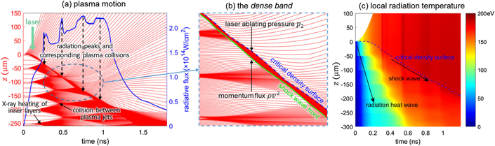
Figure 1. (a) Plasma motion and radiative flux for multilayer films with 50 μm gaps. The vertical axis (z) is along the normal direction of the target plane. Red lines refer to the path lines of plasma. The blue solid line is the radiative flux emitted out of the target. The inner films are heated by x-ray and expand before the shock wave propagates there. The peaks of radiative flux curve correspond to the collisions between the shock wave front and plasma jet. (b) The narrow region of dense plasma between the shock wave front and the critical density surface (dense band). (c) Local radiation temperature evolution. The radiation heat wave propagates much faster than shock wave, indicating the radiation heat wave is supersonic.
Download figure:
Standard image High-resolution image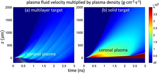
Figure 2. Coronal plasma expansion. The two frames use the same colormap shown on the right. The plasma fluid velocity is weighted by plasma density to evaluate the coronal plasma expansion. The color of coronal plasma of multilayer target is significantly lighter than that of solid target, indicating that the coronal plasma expansion for multilayer target is slower. Here, the laser pulse is 2 ns square wave.
Download figure:
Standard image High-resolution image2.2. Laser spot movement
The movement of laser spot changes the spatial distribution of the radiation field in the hohlraum, and makes the symmetry control difficult. The laser energy depositing position changes as the critical density surface moves, which indicates the movement of laser spot (figure 3). For multilayer target, the laser spot move into the inner of the target and its speed can be controlled by changing the gaps between films: smaller gaps result in lower inward speed. This is similar to changing the density of foam target. By adjusting the gaps, the movement of laser spot can be reduced to minimum.
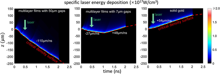
Figure 3. Movement of the laser spot. The bright band of laser energy deposition in the image indicates the movement of laser spot. The dash line in red is the critical density surface. The three frames use the same colormap shown on the right. The laser spot moves inwards for multilayer targets and its speed is related to the width of the gap. For the middle frame, the laser spot turns outward at around 1 ns, because a solid gold base is attached to the bottom of the multilayer films and the solid gold is ablated in the later stage. For the solid target, the laser spot moves outwards. Here the laser is 2 ns square pulse with power density 2.0 × 10¹⁴ W cm−2.
Download figure:
Standard image High-resolution imageHere we derive a model to quantify the speed of critical density surface for planar multilayer film target, which can be used to estimate the speed of laser spot. In general, the shock wave is always faster than (or close to) the critical density surface, which means that the dense band may become wider. However, in the condition mentioned below, the shock wave speed and the critical surface speed are very close to each other (figure 1(b)), and they are assumed to be the same (v). The fluid velocity of the plasma before shock wave is assumed to be 0, since the global averaged velocity of local plasma motion is 0 according to momentum conservation. The momentum conservation condition of the shock wave discontinuity gives:

Here p1 is the pressure before the shock wave while p2 is the pressure of shocked material; ρ is the equivalent density of the multilayer films while ρ2 is the density of the shocked material; v2 is the velocity of shocked material relative to the shock wave surface (v2 ≪ v in our condition). According to the mass flux condition ρv = ρ2
v2, we have . The p1 is also negligible compared with ρv2. Ignoring the minor items, we have

The plasma pressure in the dense band is uniform. The p2 is driven by the laser (laser ablating pressure). It indicates the thermal energy density of the plasma near the critical density surface and it depends on the laser power. Equation (2) gives the relation between the speed of critical density surface v and the equivalent density ρ for a given laser power. According to simulation result, p2 is approximately proportional to the laser power PL. Therefore, the speed of critical density surface is:

where const = 2.04 × 10⁻¹⁰ ns−1 g1/2 cm1/2 W−1/2 (this value is derived from curve fitting in figure 4).
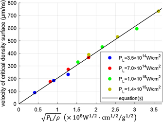
Figure 4. The simulation results of the speed of critical density surface for several targets with different gaps and for several different laser powers. The black line is plotted according to equation (3).
Download figure:
Standard image High-resolution imageThe speed of critical density surface given by equation (3) is consistent with 1D simulation result within 10% relative error (for 3.5 × 10¹⁴ W cm−2 ⩽ PL ⩽ 1.4 × 10¹⁵ W cm−2, 0.01 g cm−3 ⩽ ρ ⩽ 0.2g cm−3, and  ). Equation (3) can also be applied to foam gold for the density range mentioned above, but cannot be applied to solid gold, since the shock wave propagates significantly faster than the critical density surface in solid gold and there is no such narrow dense band in plasma.
2.3. Radiative flux evolution
For hohlraum made of solid gold, significant portion of laser energy is converted into the kinetic energy of the plasma that expands from the wall, which is useless for ignition. For multilayer film target, the plasma kinetic energy is converted into internal energy during plasma collisions, and the heated and compressed plasma generates strong x-ray emission. Therefore, the radiative flux is increased by collisions. Compared with solid target, the radiative flux of multilayer target is about 12% higher (figure 5(a)). Figure 5(b) shows that the plasma kinetic energy of multilayer target is lower than that of solid target, while the plasma internal energy and radiation energy is higher. As figure 1(a) shows, there are two types of plasma collision in multilayer target: (1) the collision between plasma jets; (2) the collision between shock wave front and plasma jet. For the later, the plasma in the dense band are compressed (and therefore heated) by the collision, and strong x-ray is emitted out of the target since the corona is optically thin. The radiative flux reaches a peak each time the shock wave front collides with a plasma jet. For the former, the collisions are always accompanied by rarefactions. The effects of compressing and rarefaction cancel out. Therefore, they contribute little to the enhancement of x-ray emission. For multilayer target with smaller gaps, the radiation peaks are flatter (figure 5(a)). This can be explained as follow. The plasma jets tend to be less nonuniform after several collisions (collisions of type 1). The radiation peaks become flatter while the shock wave front collides with less nonuniform plasma jets. Smaller gaps lead to more frequent collisions between plasma jets, resulting in flatter radiation peaks. In practice, the plasma collisions are not synchronized for the whole surface of the wall. The 3D effect cannot be simulated by 1D program. Therefore, the practical radiation peaks are expected to be flatter than the simulation result. Furthermore, plasma collisions increase only soft x-ray rather than M-band x-ray which is harmful to ignition.
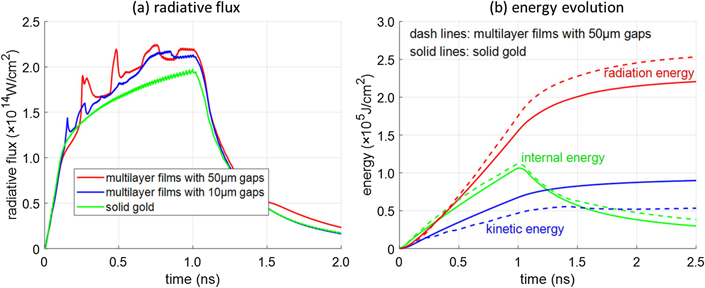
Figure 5. (a) Radiative flux for multilayer targets and solid target. The radiative flux of multilayer target is about 12% higher than that of solid target. The peaks on the curve of multilayer target with 50 μm gaps are sharper than that with 10 μm gaps. (b) Evolution of plasma internal energy, plasma kinetic energy and radiation energy (energy of x-ray that escaped from the target). The kinetic energy of multilayer target is 30% lower than that of solid target.
Download figure:
Standard image High-resolution image3. Experimental demonstration
Experiment of laser ablated planer targets was conducted on SGIII prototype. Multilayer target and solid target were ablated in a same shoot for comparison. Multilayer gold films are separated by notched holders made of stainless steel (figures 6(a) and (b)). The thickness of films is 200 nm while the width of the gaps is 70 ± 10 μm, providing equivalent density of 55 mg cc−1. A solid gold base is attached to the bottom of the target, providing multilayer target on one side and solid target on the other side. The target plane is in the horizontal plane. Laser beams are grouped into the upper beams and lower beams, both of which contain 4 beams. The two groups of laser hit the two sides of the target respectively at 45° angle (figure 6(d)). Each beam is designed to convey 800 J energy in 2 ns square pulse. The laser spot is round with diameter of 500 μm aimed at the center of the target, providing power density of 8.2 × 10¹⁴ W cm−2. For larger laser spot area, the ablation is closer to 1D planar case while the laser power density is lower due to the limited laser energy. Flat response x-ray diodes (FXRDs) and M-band x-ray diodes (MXRDs) were used to measure the emitted soft x-ray flux and the M-band x-ray flux respectively. Slit imaging system with M-band filter images the M-band emission of the target with 1D space resolution in the normal direction of the target plane, and an x-ray streak camera (XSC) was used to record the time-resolved 1D image (figure 6(c)). Both multilayer target and solid target are quadrate with dimension of 800 μm × 800 μm. For larger target area, the plasma generated from the target margin obscures the M-band x-ray and decreases the counts of XSC significantly (see section 3.1); for smaller target area, the risk of deviation of the laser hitting point is higher. The experiment was repeated by 4 shots. In two shots, the multilayer target was on the top while the solid on the bottom; in another two shots, the target was turned upside down, which helps to eliminate the error of detecting efficiency of diagnoses in different view angles. 2D simulation (program name: icefire-2D [14]) in cylindrical coordinate was implemented to characterize the edge effect. The square target is replaced with round target (Φ800 μm) without film holder. The laser beams are ideal cones with 45° half apex-angle. The opacity data and EOS are the same as used in 1D simulation.
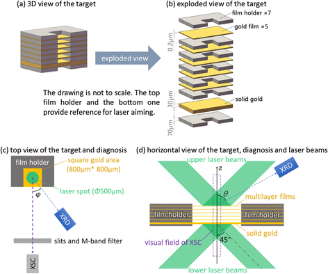
Figure 6. Experimental target design and diagnosis configuration. The gaps between gold films depend on the thickness of the film holder. The multilayer films and the film holders are assembled using glue. The notch on the film holder exposes a square gold area. The laser beams hit the center of the square gold area at 45° angle. The target plane is in the horizontal plane. The XSC view direction is also in the horizontal plane.
Download figure:
Standard image High-resolution image3.1. Discussion of XSC result
Since M-band x-ray is mainly emitted from the laser irradiated coronal plasma, the XSC result can provide information of coronal plasma motion and laser energy deposition. Figure 7(a) shows the XSC frame recorded in experiment. Two bright areas appear in the frame, respectively corresponding to the two laser spots on the two sides of the target: the upper bright area is the image of multilayer films while the lower is of solid gold. Figure 8 shows how the plasma motion effects on the XSC frame. The image of multilayer films is dim, and it resolves the multilayer structure: the alternate bright and dark bands. This is caused by the plasma generated from the target margin (non-spot region, figure 8(d)) as the laser spot drills into the multilayer films. The M-band x-ray serves as the backlight source for the imaging of the target margin which does not emit but absorbs M-band x-ray. Indeed, the plasma in spot region losses its multilayer structure when it is sprayed into the corona (see section 2.1). The alternate bright and dark bands reflect the multilayer structure of plasma in the target margin. In the early stage, the bright bands correspond to the vacuum gaps and the dark correspond to the films. The pattern changes along with time: the bright become dark in the later stage while the dark become bright. The evolution of the pattern reflects the evolution of the plasma in the margin region. The non-spot region is ablated by the x-ray emitted from the spot region. The plasma in the non-spot region retains multilayer structure and behaves similarity to the plasma underneath shock wave front (see section 2.1: x-ray ablated region in 1D simulation): the plasma coming from each film expands and collides with each other (figure 8(b): local plasma motion in the target margin). The local plasma density changes along with plasma compression and rarefaction, resulting in the change of the pattern. In the later stage, the contrast ratio between the bright bands and dark bands decreases, because the local plasma density becomes less nonuniform after plasma collisions. For comparison, figure 7(b) shows the simulated XSC result. The detailed structure of alternate bright and dark bands on the two frames appears slight difference. The laser pulses are not ideal square wave and the laser beams are not ideal cone in experiment. Therefore, the behavior of plasma collisions in experiment is slightly different from that in simulation, introducing the difference mentioned above. The image of solid gold resolves a sharp inner boundary, which indicates the movement of critical density surface (see 'critical density surface' marked in figure 7): the laser reflecting surface is not exactly but very close to the critical density surface for non-perpendicularly incident laser, due to the high gradient of plasma density near critical density surface. It moves outwards with speed 60 ± 10 μm ns−1 for experimental result. The 2D simulation result is 37 μm ns−1 while 1D simulation is 18 μm ns−1. For multilayer films, the inner boundary is not as sharp as that of solid gold, because the critical density surface is concaved during ablation (refer to figure 8). It moves inwards with speed 184 ± 30 μm ns−1 for experimental result. The 2D simulation result is 180 μm ns−1 while 1D simulation is 245 μm ns−1, and the equation (3) gives 248 μm ns−1. The 1D simulation result (as well as the result of equation (3)) is significantly higher than the results of 2D simulation and experiment for multilayer target but significantly lower for solid target, because in 1D case the laser power density near critical density surface is higher: (1) the 45° laser beams diverge when the critical density surface departs from the focus plane of the laser beams; (2) the optical thickness for perpendicularly incident laser to propagate to reflecting surface is shorter. It is difficult to compare the coronal plasma density between multilayer films and solid gold by analyzing the XSC result because of the influence of the plasma in non-spot region. In conclusion, wall plasma expansion is mitigated by replacing solid gold with multilayer gold films.
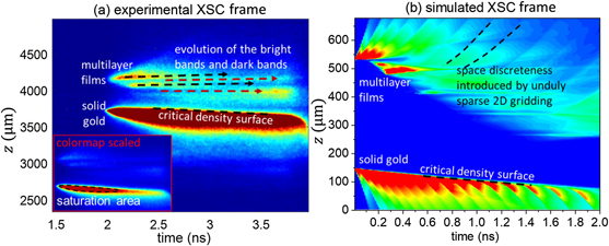
Figure 7. XSC results. The vertical axis of the frames refers to the dimension in the normal direction of the target plane. In the experimental frame, part of the solid gold image is saturated because the laser missed the target center of solid gold and hit the target margin. The image at the bottom-left corner with colormap scaled shows the saturation area. In the simulated frame, the periodic structure which sprays out along with coronal plasma is introduced by the unduly sparse 2D gridding. The critical density surface moves inward for multilayer films but outward for solid gold. Wall plasma expansion is mitigated by multilayer films.
Download figure:
Standard image High-resolution image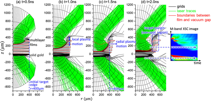
Figure 8. Grid evolution for 2D simulation. Cylindrical coordinate was used with two parameters: r (radial dimension) and z (axial dimension, in the normal direction of the target plane). Laser spot drills into the multilayer films. The multilayer films are concaved, forming a half chamber. The half chamber decreases the escaped x-ray energy and increases the radiation temperature. The target margin of multilayer films (non-spot region) is ablated by the x-ray and expands in the radial direction. Local plasma motion in axial direction causes plasma collision and rarefaction in the non-spot region. Nonetheless, there is no global plasma motion in axial direction such as spraying out or moving inward. This is consistent with the experimental XSC result that the alternate bright and dark bands almost remain motionless. The critical density surface for multilayer films stops moving inward at around 1.5 ns due to the plasma pressure from solid gold. For solid gold, the critical density surface is flat rather than concaved, resulting in the sharp boundary on the XSC image.
Download figure:
Standard image High-resolution image3.2. Discussion of XRD results
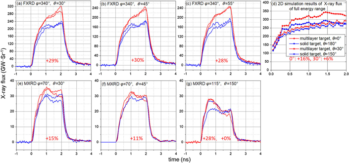
The emitted x-ray flux was measured by 3 FXRDs and 3 MXRDs mounted on different view angles. In order to compare the x-ray flux between multilayer films and solid gold, the measured x-ray flux is normalized by the practical laser energy, since the practical laser energy differs from shot to shot (by ∼10%), and the x-ray emission is strongly correlated to the laser energy. The FXRDs obtained consistent result: the x-ray (full energy range) flux of multilayer films is about 30% higher than that of solid gold (figures 9(a)–(c)). The measured M-band x-ray flux of multilayer films is also higher (figures 9(e)–(g)). Although the percentage (0%–28%) differs from shot to shot, from MXRD to MXRD, it is overall lower than that of FXRD, indicating that the M-band fraction is lower. The 2D simulation result of full energy range x-ray flux of multilayer films is 16% higher than that of solid gold at 0° (180°) view angle and 6% higher at 30° (150°) view angle (figure 9(d)). The difference between experiment result and simulation result may due to the asymmetry structure of the film holder which restrains the plasma from transverse expansion (in the direction parallel to the target plane) on the three close boundaries of the square multilayer films. The multilayer target is concaved during ablation, forming a half chamber (figure 8). The half chamber decreases the escaped x-ray energy and increases the radiation temperature. However, the target margin obscures the emitted x-ray in large angle (angle to the target normal), especially when laser spot area is not sufficient large. Therefore, the emitted x-ray is anisotropic and the above result of XRDs is guaranteed by the view angle of the XRDs. The peaks on radiative flux curve caused by plasma collision in 1D simulation results cannot be characterized on the measured x-ray flux curve: the noise of the detector overrides the radiation peaks which are expected to be flatter than the results of 1D simulation.
Figure 9. XRD results. The red lines refer to multilayer films while the blue refer to solid gold. The view angle of the XRD is specified by the parameters θ and φ, which are defined in figures 6(d) and (c) respectively. The percentages in red indicate the proportion of the x-ray flux of multilayer films that exceeds the flux of solid gold. The MXRD result in figure 9(f) missed data of one shot due to malfunction of the diagnostic device. The ripple of the curve of 2D simulation is due to the unduly sparse gridding rather than plasma collision.
Download figure:
Standard image High-resolution image
4. Conclusions
Multilayer film structure is designed for hohlraum used in ICF. 1D simulation reveals the characteristics of the laser ablated planar multilayer target: the supersonic radiation heat wave heats the inner multilayer films before the shock wave propagates there and the heated films engender local plasma collision; plasma collisions between shock wave front and the plasma jets generate strong x-ray and increase the radiative flux; the laser spot moves inwards for multilayer target, and its speed can be controlled by changing the gaps between films. A model is proposed to quantify the relation among the speed of critical density surface, the laser power, and the equivalent density of the multilayer films. It is consistent with simulation result within 10% relative error. Experiment result of XRDs demonstrates that the x-ray flux of multilayer films is higher than that of solid gold. 2D simulation indicates the flux of multilayer films is anisotropic due to the edge effect especially when laser spot area is not sufficient large. The experimental XSC image demonstrates that the critical density surface of multilayer target moves inward and its speed is consistent with 2D simulation result. The plasma collision was observed by the XSC as well. The multilayer gold film has the same advantages as foam gold, while it is easier to be fabricated and more flexible to change its equivalent density. Multilayer films can replace foam used in hohlraum especially for the materials that cannot be made into foam.
Acknowledgments
This work was supported by the National Natural Science Foundation of China (Grand Nos. 11305160, 11405160, 11775204, 11805186, 11805187, 12075218).