
Abstract
Objective. The ease of use and number of degrees of freedom of current myoelectric hand prostheses is limited by the information content and reliability of the surface electromyography (sEMG) signals used to control them. For example, cross-talk limits the capacity to pick up signals from small or deep muscles, such as the forearm muscles for distal arm amputations, or sites of targeted muscle reinnervation (TMR) for proximal amputations. Here we test if signals recorded from the fully implanted, induction-powered wireless Myoplant system allow long-term decoding of continuous as well as discrete movement parameters with better reliability than equivalent sEMG recordings. The Myoplant system uses a centralized implant to transmit broadband EMG activity from four distributed bipolar epimysial electrodes. Approach. Two Rhesus macaques received implants in their backs, while electrodes were placed in their upper arm. One of the monkeys was trained to do a cursor task via a haptic robot, allowing us to control the forces exerted by the animal during arm movements. The second animal was trained to perform a center-out reaching task on a touchscreen. We compared the implanted system with concurrent sEMG recordings by evaluating our ability to decode time-varying force in one animal and discrete reach directions in the other from multiple features extracted from the raw EMG signals. Main results. In both cases, data from the implant allowed a decoder trained with data from a single day to maintain an accurate decoding performance during the following months, which was not the case for concurrent surface EMG recordings conducted simultaneously over the same muscles. Significance. These results show that a fully implantable, centralized wireless EMG system is particularly suited for long-term stable decoding of dynamic movements in demanding applications such as advanced forelimb prosthetics in a wide range of configurations (distal amputations, TMR).
Export citation and abstract BibTeX RIS

Content from this work may be used under the terms of the Creative Commons Attribution 3.0 licence. Any further distribution of this work must maintain attribution to the author(s) and the title of the work, journal citation and DOI.
1. Introduction
Human–machine interfaces have been extensively studied in the last decade, particularly in the context of motor function restoration in impaired patients. While brain–machine interfaces for tetraplegic patients are still limited to laboratory settings [1–3], electromyography-based interfaces for amputated patients are already available in commercial systems. Indeed, when still obtainable, the electrical signals provided by the peripheral nervous system have proven to be ideal to control prostheses with high-degrees of freedom [4]. In that framework, machine learning decoding algorithms applied to recorded peripheral signals aim to provide a reliable and natural control of robotic limbs. Nevertheless, the clinical applications are still limited nowadays for several reasons, spanning from ease of use to aesthetic appearance and effective costs [5].
Advances in robotics allow to design hand prostheses that perform a wide range of movements, almost comparable with those of an intact hand [6]. However, current commercial hand prosthetics generally show only one or two controllable degrees of freedom in their movements. As an example, a 2-DOF state-of-the-art prosthesis (Michelangelo Hand, Otto Bock Healthcare GmbH) allows closing/opening of the hand with different grip types, and uses surface EMG (sEMG) activity from a pair of muscles for control. The control is thus robust, but is necessarily sequential: users open and close the hand by contracting one or the other muscle, and switch the grip type by co-contracting these muscles. While such prostheses significantly improve the patients' quality of life, users would benefit greatly from faster and more intuitive control of the hand.
These constraints are not due to electromechanical design, but mostly imposed by limitations in the control signal, here the sEMG. sEMG is relatively easy to record, by placing gel or dry [7] electrodes on the skin over the muscle of interest. However, these signals are frequently affected by changes in sensitivity (e.g. skin conductivity, sweating), or artifacts from movements, which decreases the robustness of the control and would require the user to recalibrate more complex decoders frequently [8, 9]. More importantly, additional layers of tissue (e.g. subcutaneous fat, skin) between the signal source and the electrodes make activity from neighboring muscles difficult to separate due to cross-talk [10], and recording of small or deep muscles is limited [11, 12]. This affects the ability to record richer peripheral information, such as EMG activity from residual hand muscles of the lower arm in the case of distal amputations, or from more proximal muscles on which a targeted muscle reinnervation procedure was performed [13]. As a consequence, standard sEMG recordings lack the richness and stability required for fine and natural control of high-DOF hand prostheses.
On the other hand, acute intramuscular EMG (iEMG) measurements do not show these shortcomings, and allow recording from a large number of small and deep muscles, which provide enough independent control signals for a more natural control of complex prostheses [14]. However, acute iEMG recordings are best suited for short-term clinical use, as transcutaneous wires are a serious drawback for prosthetics, due to the discomfort and risk of infection in long-term use.
The Myoplant system, a fully implantable, battery-free, and wireless iEMG recording system, was developed to overcome the drawbacks of acute iEMG recordings. Both power and signals are transmitted to and from the implant wirelessly, and electrodes are placed epimysially, in direct contact with the muscles of interest [15]. Ultimately, such an implant would not require daily placement of the electrodes, making it easier to use than sEMG, while providing good quality and stable intramuscular signals, at the cost of requiring surgery for the implantation. In contrast to one of the few currently existing and tested wireless iEMG systems, such as IMES [16], the Myoplant system uses a centralized implant. It thereby allows separating recording locations from transmission location with the potential of optimizing the transmission location, minimizing the energy costs for power induction and simplifying the antenna configuration for data read-out.
Myoplant prototypes were previously tested for shorter periods of time in monkeys [17, 18], which allowed a proof of concept with basic function and biocompatibility tests of the implant, but no extended EMG recordings which could have been correlated with behavior. In this paper, we present the result of long-term implantation of this system in two monkeys, and demonstrate the validity of this wireless iEMG approach for long-term prosthetic by comparing it to equivalent sEMG recordings. For this, we show two different and representative aspects of EMG use in prosthetics, namely the ability to decode continuously varying force-related movement parameters, and the ability to decode discrete arm movement directions. Wireless iEMG and coincident sEMG are compared in these two scenarios, both on a short timescale and longer timescale, in order to assess the reliability of the decoding in time.
2. Methods
2.1. Implant
The Myoplant system is composed of two main components, a central implant, containing the electronics [19, 20], and four thin epimysial bipolar electrodes (figure 1(a)). The central implant, previously described [18], performs analog band-pass filtering of the electrode signals (6–1500 Hz), variable-gain amplification (electrode specific pre-amp gains of approx. ×48, ×1/2/12/24 selectable post-amp gain), and digitizing (10 bits at 3571 Hz per channel). The digitized data is then wirelessly transmitted to a base station (Zarlink ZL701012, MICS RF band 402–405 MHz), which is connected to a computer for data logging. The implant is powered by induction coupling, via a custom-made inductor and power supply. For testing purposes, the amplification stage of one of the implant channels (posterior deltoid electrode) was configured differently, which predictably rendered its signal unusable at the selected gain. This channel was thus excluded from the subsequent analyses.
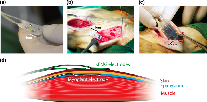
Figure 1. Implantation of the electrodes and transmitter. (a) View of the flexible bipolar electrodes. (b) Implantation procedures for the epimysial electrodes in upper arm muscles. (c) Implantation of the wireless implant in the back of the animal. (d) Recording configuration. The iEMG electrodes were placed on the thickest part of the muscle, between the muscle fibers and the epimysium. The surface electrodes were placed as best as possible right above the implant. Both recording systems used a bipolar configuration, with the two contacts along the direction of the muscle fibers.
Download figure:
Standard image High-resolution image2.2. Implantation
Two male macaque monkeys L (7.5 kg, age 12) and Z (14.25 kg, age 15) received implants. The implantation was performed under general anesthesia (isoflurane). First, the electrodes were implanted in the muscles of interest (biceps, triceps, 2 electrodes in the lateral deltoid) [15]. For this, the skin was opened with an approx. 5 cm cut parallel to the direction of the fibers in the muscle of interest to expose the muscle. Next, smaller openings of approx. 5–10 mm were made in the epimysium, perpendicular to the direction of the muscle fibers. The electrodes were slid into a pocket or tunnel of approx. 2–4 cm length created by blunt dissection between the epimysium and the muscle (figure 1(b)). Tunnels were used to pull the electrode with a hemostat from the side opposite to the insertion, while pockets were used as an alternative when pulling was not possible. The electrodes were sutured to the epimysium, either at both ends of the electrode or on the wire-end only, depending on the stability of the epimysial pocket. The wires from the different electrodes were routed below the skin towards an opening made in the back of the animal, below the shoulder blades, where the central implant was placed (figure 1(c)). The electrode wires were connected to the central implant (Omnetics NCP/NCS-06-WD-18.0-C, sealed with medical purpose silicon WPI Kwik-Sil), which was then placed within the latissimus dorsi for stability. All openings were sutured using resorbable threads. The earliest recordings were conducted one week after the implantation.
During previous surgeries, both animals had already been implanted with a skull-mounted titanium head holder, used for accompanying neurophysiological recordings and video-based control of eye movements [21]. All experimental procedures were conducted in accordance with European Directive 2010/63/EU, the corresponding German law governing animal welfare, and institutional guidelines.
3. Experiments
3.1. Recording configuration
During recording sessions, the monkeys sat in custom-built primate chairs The chair, in combination with head-fixation, let the experimenters access the back of the monkeys for positioning the external primary induction coil and the data receiving antenna of the iEMG implant. It also allowed placing the sEMG electrodes. A front opening in the chair allowed the animals to perform the task with the implanted arm using the haptic interface or touch screen.
For iEMG recording, a single PCB including both the inductive power coil and the wireless antenna was maintained right over the location of the implant, as close as possible to it. The PCB was connected to a base station for the wireless communication and to the inductive power supply by separate RF shielded cables (figure 2(a)). To be close to the implant and to minimize translational offsets or tilts between sending and receiving coils due to the animals' movements, the PCB was either held by hand against the skin or fixed to the skin via velcro tape. After initial testing, the implant was configured with a post-amplifier gain of ×12, as it gave signals with a large dynamic range over a maximum number of electrodes. The bit depth was set to its maximal value of 10 bits, which allowed a recording of the iEMG data at a sampling frequency of 3571 Hz per channel.
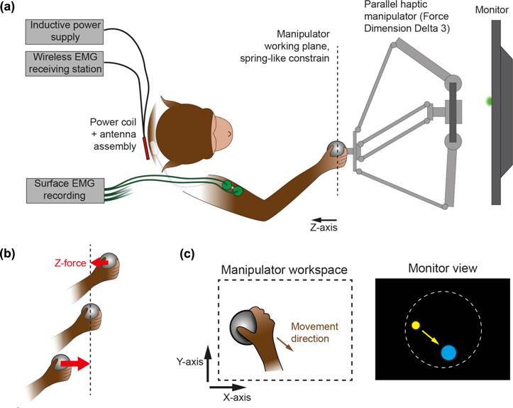
Figure 2. (a) Schematic of the haptic setup during recording sessions, top view. (b) Detail of the force generation for constraining the handle in a fronto-parallel plane. (c) Cursor reach task. The movement of the manipulator handle (represented below as the gray ball) controls the cursor movement (yellow circle). The goal of the task is to place the cursor in the target (here represented in blue).
Download figure:
Standard image High-resolution imageDuring some sessions we made concurrent recordings of bipolar sEMG and iEMG from the same muscles (figure 1(d)). To have sEMG signals that were maximally consistent between days and as comparable as possible to the iEMG signals, we placed the sEMG electrode pairs right above the iEMG electrodes: their location could be felt by touch, and were also marked on the skin. Each day the skin was shaved and thoroughly cleaned with ethanol so as to have a good contact with the surface electrodes. The disposable surface electrodes were large in order to avoid any isolating effect of the implanted electrodes, and had a strong adhesive gel (Technomed Europe, 20 mm diameter disk, TE/K50430–002), and were additionally maintained in place using self-adhesive sports bandages. The common reference electrode was placed at the back of the skull of the monkey. The sEMG electrode wires were routed toward the opening in the back of the primate chair. The sEMG signals were then amplified and digitized by a GTEC g.USBamp device (Guger Technologies), using a sampling of 4800 Hz/16 bits (differential mode, 2–2000 Hz bandpass and 50 Hz notch filtering).
In order to synchronize the recordings from the iEMG and sEMG with the visual task instructions to the monkey and its behavioral responses, the task control systems sent 4 bit TTL signals and a strobe pulse to both the iEMG wireless base station and the sEMG recording system. The 4-bit value and the timing of the strobe pulses were stored with the EMG data to allow offline synchronization.
3.2. Haptic task
Monkey L performed a cursor reach task by grasping and moving the spherical handle of a sturdy parallel-type haptic manipulator (Force Dimension delta 3). The manipulator was connected via USB to a computer (Mac Mini) running custom software (C++, OpenGL) in charge of stimulus presentation, task event control, force computation, and associated data recording. The manipulator and the computer communicated bidirectionally at 2 KHz, the manipulator sending the 3D position of the handle and the computer requesting forces to be applied at the handle for each iteration of this 0.5 ms haptic cycle.
The movements of the manipulator handle in the fronto-parallel plane were visualized in real-time (monitor and haptic device latency were fully compensated by a forward prediction) at 1:1 scale via a yellow cursor displayed on an LCD monitor (cursor diameter 6 mm, screen size 590 × 338 mm, BenQ XL2720T, distance to eyes approx. 75 cm, figure 2(c)). The task of the monkey was to place this cursor within a circular target (diameter 50 mm). At the beginning of each new trial, the target could appear at random locations within a circular workspace (diameter 160 mm, centered on the monitor), and at least 80 mm away from the current cursor location. The animal had 30 s to initiate its movement, and then 5 s to reach the target. When the target was acquired (cursor fully within the target, speed of the cursor below 0.2 mm s−1), the cursor had to stay in for 300 ms, after which a liquid reward and a sound feedback were delivered to the animal. In case of failure, a different sound was played, and a new trial initiated.
The handle workspace was limited according to the task design: its movements were constrained within a fronto-parallel (x–y) working plane through forces applied by the manipulator (distance to eyes approx. 35 cm). These forces were equivalent to those of an ideal dampened spring which always pulled the handle towards the working plane in an orthonormal fashion (figure 2(b)). The z-axis of the manipulator pointing toward the monkey, the z-component of the force was thus computed as  (with
(with  and
and  To prevent the manipulator from hitting its mechanical boundaries, additional forces constrained its handle within a 240 mm diameter circular area in the working plane.
In some sessions, the manipulator imposed resistive forces that opposed the movements within the working plane. The value of these forces was determined from the cursor kinematics and added to the workspace constraining forces. Some sessions used a viscous-like force, with  (with l being 0, –10 or –20
  while others used kinetic friction-like forces (
 with k being 0 or –3 N). Within a session, the color of the target indicated to the animal the force level that was used in each trial.
Manipulator position and total applied force signals were resampled at 500 Hz, and smoothed using cubic smoothing splines.
3.3. Touchscreen task
The monkey Z performed a visually guided center-out reach task on a touchscreen placed in the fronto-parallel plane (Intellitouch ELO Systems, 27'' monitor, 50 cm distance to eyes). In this task, the monkey initiated a trial by touching a central fixation target (0.5 mm square, tolerance radius 2.5 cm). The monkey had to keep touching this target while it stayed displayed on the screen (between 500 ms and 1 s). At the same time as the fixation target disappeared, the peripheral reach target could appear at one of eight possible locations (four cardinal directions and four diagonal). The monkey had then to reach to the reach target location within 1 s, and was rewarded with a drop of liquid after a holding period (300 ms) if successful. The reach targets (1 cm radius circle, 3 cm tolerance radius) were uniformly distributed on a circle centered on the fixation target (radius 90 mm) [18]. In this task, only the reach endpoint position was registered via the touchscreen, while no continuous movement parameters could be recorded.
3.4. EMG processing
Both sEMG and iEMG raw signals were band-pass filtered (5th order Butterworth filter, with 40 Hz and 500 Hz lower and upper cutoff frequencies), and the following time-domain features were extracted from these filtered signals: mean absolute value (MAV, 250 ms sliding window, 1 sample step), its slope (MAVS, 100 ms window, 1 sample step), the waveform length (WFL, 250 ms window, 1 sample step) [18]. All features were then resampled at 500 Hz using cubic smoothing splines. Spectrograms were computed using FFT for frequencies from 1 to 500 Hz, with sliding Hamming windows containing 2000 samples (1000 samples step).
3.5. Continuous decoding of force (monkey L)
From the data collected during the haptic task, we aimed to decode the instantaneous force exerted by the monkey on the manipulator handle in the z-axis, as this corresponded to the direction in which the force varied maximally: the monkey 'pulled' the handle during the movements. We treated decoding of the force level from the EMG data as a nonlinear regression problem and approached it with an artificial neural network decoder. For each time point, the decoder inputs were the EMG features described above for each of the used EMG channels  and the force generated by the manipulator in the z-axis, used as a proxy for the actual pulling force exerted by the monkey, was set as the output. The artificial neural network was a radial basis function network with gaussian activation functions and linear outputs (Netlab toolbox 3.3 http://aston.ac.uk/eas/research/groups/ncrg/resources/netlab, 18 hidden units and 4 iterations of 2-stage training: EM fit of a gaussian mixture model to find RBF centers, least-square fit to determine output weights).
The recordings of task data, sEMG data and iEMG data started and stopped at different times. Moreover, the wireless connection for the iEMG sometimes dropped due to power fluctuations or movement of the animal, which required to start the recording again. In order to make data manipulation and selection easier, each session was divided in epochs of two seconds, and within each epoch, the availability and validity of each type of signal (force, iEMG, sEMG) was assessed. Given the continuous nature of the task and the fact that the parameters of the force generation were constant within the task, these epochs were not aligned with trial events. Since the decoder we used was time-independent, the processed force and EMG features were concatenated over the selected epochs.
In the haptic task, the monkey L was free to let go of the robot handle at any time, which would cause the EMG and force to become unrelated. Such periods were excluded from the dataset on the basis of a speed criterion (manipulator handle speed below 0.02 mm s−1, 53% of the data points rejected). The EMG features in both systems could also present artifacts. Periods during which such artifacts appeared were removed using outlier detection in the features. To this effect, portions of the data in which one of the features reached values above four standard deviations for this feature were excluded (5% of the data points rejected for iEMG, 2% for sEMG). Last, each feature was normalized in a robust manner, by dividing the signal by the value of its 90th percentile.
Within each recording session, the selected data was separated in one minute long blocks. Subsets of blocks were used to train and test the decoder with a leave-one-out cross-validation approach. For each of these time blocks  a decoder was trained using the data from all the other blocks from the same day
  The decoder could then be tested on data from that block
  (within-day decoder), as well as on each block from the other days
  (across-day decoder). This procedure allowed us to assess the performance of the decoders within each day via cross-validation, and also to test the generalization of the decoders across other days (figure 3). The dataset resulting from this selection consists of 157 one-minute-long blocks collected over 14 different days for sEMG, and 146 blocks over 22 days for iEMG.
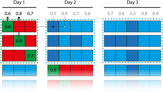
Figure 3. Cross-validation procedure. Each square represents a block of data (1 min of continuous data for the force decoding, 80 trials for the movement direction decoding). Each row in the figure represents the training and testing sets of a single decoder. Red squares indicate the training dataset, and green squares the within-day cross-validation datasets (the associated numbers represent the corresponding performance). Blue squares indicate between-day cross-validation datasets. In some analyses, the between-day performance was only tested on datasets that were at least as well decoded within day as the currently tested decoder (light blue squares).
Download figure:
Standard image High-resolution imageThe performance of the continuous force decoding was quantified using the Pearson's linear correlation coefficient between the decoded force and the actual recorded force.
3.6. Discrete decoding of reach directions (monkey Z)
No continuous movement parameters were available for the touchscreen task. Therefore, we treated decoding of the movement direction from the EMG data in the touchscreen task as a classification problem, which was approached using support vector machines (libsvm toolbox for Matlab http://csie.ntu.edu.tw/~cjlin/libsvm/, linear kernel). The decoder inputs consisted of the EMG features for each of the used EMG channels. The output corresponded to the eight discrete different movement directions.
The dataset used for training and testing the decoders was generated by selecting the successful trials, during which the monkey reached the instructed target within required time. For the same reason as detailed above, the availability of each type of signal was assessed (iEMG, sEMG), this time within each trial. The EMG features were extracted between 800 ms before movement offset (registration of the touch signal at the target location) and 200 ms after movement offset, for a total time window of 1 s. A shorter time window was also tested by extracting the EMG features for only 300 ms before movement offset. The input data for the decoder for a single trial is therefore consisting of the concatenated time series, i.e. a vector of length  In order to provide adequate input to the SVM decoder, each element of the input vector was normalized within each day by computing its z-score across trials.
In a similar fashion to what is described above for the force decoding, the data from each day was separated in blocks of 80 trials, which allowed us to perform within-day cross-validation and test the generalization of the decoders across other days. The performance of the decoding was quantified using the proportion of correctly predicted directions (chance level is therefore 1/8). The dataset consists of 62 blocks of 80 trials collected over 14 separate days for sEMG and 48 blocks over 13 days for iEMG.
4. Results
4.1. Decoding of force
With a decoding approach, we quantified how informative the iEMG compared to the sEMG is about the force that monkey L applied on the haptic manipulator during movements. We will first focus on decoding within single recording sessions and then compare both signals in terms of stability over 5 months of recording.
The pulling force generated by the monkey was well coupled with the activity of the recorded muscles, as can be seen in the sample data from figure 4. The peaks in the force (a) correspond to periods of stronger activity in the biceps EMG signal (b), (e), and are also visible in the EMG-MAV, used as example feature here (d), (g). The coupling to mechanical force is visible for both the simultaneously recorded iEMG and sEMG signals. The signal quality, and notably the dynamic range of the example feature, generated from filtered data, appears to be comparable between the two recording systems, while the raw signals and the spectrograms (c), (f) show different noise characteristics.
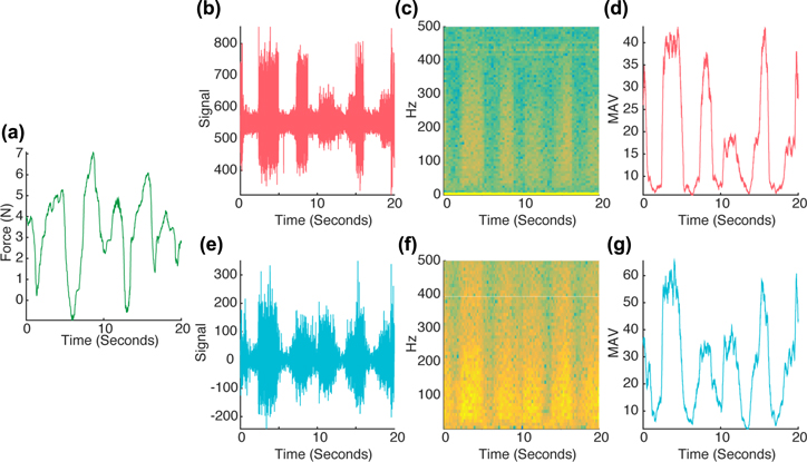
Figure 4. Sample of the synchronized data used for force decoding. The decoding consists of retrieving the pulling force exerted by the monkey (a) from features extracted from the EMG signal such as the biceps MAV ((d): iEMG, (g): sEMG). The biceps raw EMG signal ((b): iEMG, (e): sEMG) and corresponding spectrograms ((c): iEMG, (f): sEMG) for from the two systems are also shown.
Download figure:
Standard image High-resolution imageBoth iEMG and sEMG can achieve good decoding performance within a recording session, yet iEMG on average performs better. The correspondence between the iEMG and sEMG signals and the force allowed the neural networks to decode the pulling force from EMG features. When decoders that are trained on blocks of data from a single day are tested on a different block of data from the same day, using the cross-validation procedure described in Methods (within-day), both systems typically show high decoding performance (figures 5 and 6(a)). The maximum Pearson's r observed over the different testing sets is 0.89 for the iEMG and 0.88 for the sEMG. Nevertheless, the iEMG allowed significantly more reliable decoding on average (average Pearson's r across testing blocks, iEMG: 0.72 and sEMG: 0.59, p < 0.001, linear mixed-effect model with day of recording as a random factor).
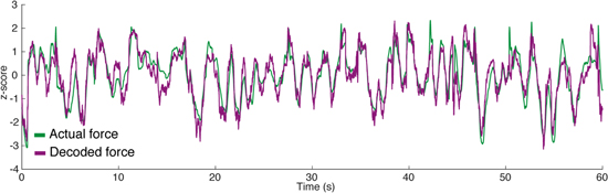
Figure 5. Sample of within-day force decoding from iEMG in a 1 min testing set. The neural network was trained on a different set of data recorded on the same day. The actual z-force as recorded from the robot is represented in green, the decoded force is represented in purple. Both traces are show as z-scores (Pearson's r = 0.89).
Download figure:
Standard image High-resolution image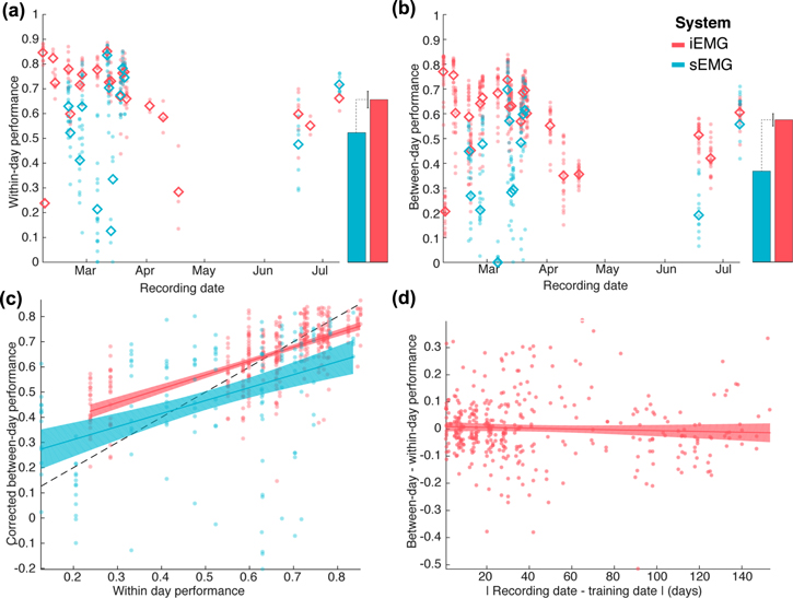
Figure 6. (a) Within-day cross-validation of force decoding performance. Performance is assessed using the Pearson's correlation coefficient between the actual pulling force and the force decoded from the EMG data. Each point corresponds to a cross-validation block. The abscissa represents the day of recording of the decoded data which here is identical to the day of training data). The solid lines represent the average cross-validated decoding performance. The bars on the right represent the parameters of a linear mixed-effect model fitted across all blocks (recording day as a random factor), with the error bar corresponding to the 95% CI of the performance difference between the two systems. Results from the iEMG are represented in red, and results from the sEMG in blue. (b) Between-day cross-validation of force decoding performance. Each point corresponds to the average performance of all decoders trained on one day when tested on the data from another day. Points are ordered on the abscissa by day of recording of the testing data. (c) Direct comparison of within-day and between-day force decoding performances. The plot represents how well a decoder performs on data from other days as a function of how well it performs on data from the day of its training. Only blocks that are decoded well from decoders from their own days are used to assess the across day performance (figure 3). The lines and shaded areas correspond to linear fits and the associated 95% confidence interval bands. (d) Influence of the time elapsed between decoder training and testing on the force decoding performance.
Download figure:
Standard image High-resolution imageDays with poor decoding performance are more frequent in sEMG (2/23 days with average performance below 0.5 for iEMG, 5/14 for sEMG). Some of the drops of decoding performance observed on figure 6(a) can likely be attributed to inconsistent execution of the task by the animal, which is often coupled with shorter recording sessions, as visible for the first and third recording sessions for the iEMG. However, the sEMG signal shows drops of decoding performance even in days during which the iEMG decoding performance was high.
The stability of force decoding across days is lower than within days, but higher in iEMG than sEMG. The figure 6(b) shows the decoding performance when cross-validation is performed between days, i.e. when a decoder trained on data from one recording session is tested on data recorded on a different day. There, it is still possible to get good decoding performance, albeit not as high as with within-day cross-validation (maximum value of the Pearson's r coefficient are 0.84 for iEMG and 0.81 for sEMG). The gap in average performance between sEMG and iEMG is however more marked in this case (average Pearson's r across testing blocks iEMG: 0.58 and sEMG: 0.41, p < 0.001 linear mixed-effect model with day of recording as a random factor).
The higher across-day stability of iEMG is not just a by-product of the higher within-day performance of iEMG compared to sEMG. In figure 6(b), the pattern of between-day decoding performance seems to roughly follow the pattern of within-day decoding performance from figure 6(a), showing that blocks that are not decoded well within days are not decoded well either when using decoders trained on different days. Moreover, a poorly performing decoder within-day is likely to show a poor decoding performance even when tested on data that is well decoded within-day. Both of these confounds are addressed in figure 6(c), which for each day, represents the corrected performance of decoders on other days as a function of their performance within day. The corrected performance (addressing the first concern raised above), is computed by only considering blocks of testing data that show a within-day performance that is at least as high as the within-day performance of the tested decoder. A linear model fitted to this data shows a significant effect of the within-day performance of a decoder on their between-day performance (slope, p < 0.001, estimate 0.54). This slope is not significantly different between sEMG and iEMG (interaction term, p = 0.64), but the intercept is higher for iEMG than sEMG (p < 0.01, effect estimate 0.1). In other words, the overall worse within-day performance of sEMG explains part of the gap in between-day performance observed in panel (b), but not all of it: iEMG does show a significantly better generalization of its decoders between days when accounting for within-day differences.
The iEMG decoding shows long-term stability over the half-year duration of recording. For iEMG, the ability of decoders to perform well on data from other days does not depend on the time between the two recording days (figure 6(d)). Here, for each pair of recording days, the drops in performance between within-day decoding and between-day decoding are plotted as a function of the elapsed time between the two days. A linear fit shows a non-significant drop in performance with time (p = 0.32, effect is −0.027 over 6 months).
4.2. Decoding of movement direction
In monkey Z we measured reach endpoints to discrete targets on a touch screen, while force of the movements was not available. The reaches executed by monkey Z generated different EMG patterns depending on the movement direction (figure 7). The curves represent the average time course of iEMG-MAV for the three implanted muscles within a recording session, as an example feature. The differences in amplitude as well as latency between EMG patterns allow the decoder to classify the movement directions from the extracted EMG features.
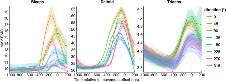
Figure 7. Direction tuning of the mean absolute value feature (MAV) traces extracted from the iEMG. Shaded areas correspond to 95% confidence intervals on the feature for each reach direction.
Download figure:
Standard image High-resolution imageBoth, iEMG and sEMG are selective for the reach direction of the monkey. Decoders trained and tested on data from the same day show similar levels of performance between the two signal types (figure 8(a)). Both systems are able to reach high levels of performance (max 86% for iEMG, max 82% of sEMG), and their average performances are not significantly different (average performance across blocks: 64% for iEMG, 53% for sEMG, p = 0.18 mixed effect model with day as a random factor). When using a shorter time window for classification (see Methods section), we obtain slightly lower decoding performances (max 83% and 80% respectively for sEMG and iEMG, averages 60% and 51% respectively, p = 0.16).
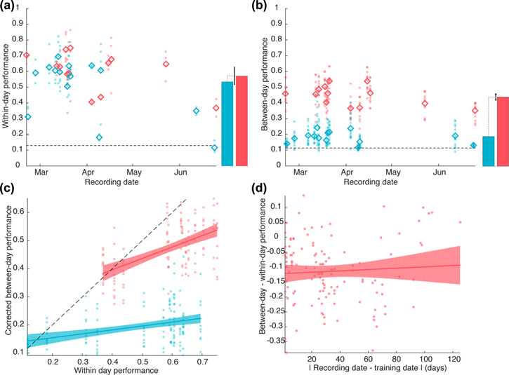
Figure 8. (a) Within-day cross-validation of movement direction decoding performance. Performance is assessed using the ratio of correct movement direction classifications. Each point corresponds to a cross-validation block. The abscissa represents the day of recording of the decoded data (and in this case of the training data too). The solid lines represents the average decoding performance. The bars on the right represent the parameters of a linear mixed-effect model fitted across all blocks (recording day as a random factor), with the error bar corresponding to the 95% CI of the performance difference between the two systems. Results from the iEMG are represented in red, and results from the sEMG in blue. (b) Between-day cross-validation of movement direction decoding performance. Each point corresponds to the average performance of all decoders trained on one day when tested on the data from another day. Points are ordered on the abscissa by day of recording of the testing data. (c) Direct comparison of within-day and between-day movement direction decoding performances. The plot represents how well a decoder performs on data from other days as a function of how well it performs on data from the day of its training. Only blocks that are decoded well from decoders from their own days are used to assess the across day performance. The lines and shaded areas correspond to linear fits and the associated 95% confidence interval bands. (d) Influence of the time elapsed between decoder training and testing on the decoding performance.
Download figure:
Standard image High-resolution image
Across days decoding of direction is more stable with iEMG than sEMG. When testing the generalization of the decoders between days, the sEMG-based decoders show a large drop of performance, almost down to the chance level, while the iEMG based decoders show a more moderate drop of performance (figure 8(b), max performance: 61% for iEMG, 41% for sEMG, average performance across blocks 44% for iEMG, 18% for sEMG, p < 0.001 mixed-effect model with testing day as a random factor). Using the shorter time window, the results are comparable (max performance for iEMG and sEMG: 61% and 38%, average performance: 42% and 17%, p < 0.001). Since the two systems show comparable within-day performance, the drop in across-day performance cannot be attributed to lower initial values of within-day performance. This is confirmed in figure 8(c), which plots the data equivalently to figure 6(c). Here the sEMG shows both a significantly lower intercept (intercept difference estimate −11%, p = 0.002) and a lower slope (interaction term between EMG type and within-day performance, p < 0.001, slope for sEMG 0.14), showing that with sEMG, the movement direction decoding across-day is worse even when good initial decoders and testing data are used. Conversely, the iEMG decoders show a more marked influence of within-day decoder performance and a higher intercept as well (slope for iEMG 0.40, p < 0.001). In other words, across-day iEMG decoding performance depends mostly on the within-day performance of the decoder that serves as basis for the across-day decoding.
Last, the across-day stability is further emphasized by the fact that with iEMG the decoders show a stable performance over time, with no significant influence of the time elapsed between training and testing (p = 0.51, slope estimate 0.036 after 6 months). There is, however a constant and significant penalty of training and testing between days (p < 0.001, intercept estimate −0.12).
5. Discussion
The fully implantable and battery-free Myoplant system allowed wireless real-time recordings of subepimysial myoelectric signals from multiple separate muscles over several months. We demonstrated in two monkeys that the wireless signals were highly informative about associated arm movements and that the decoding performance was stable over the course of the 5 month long recording periods in both animals. Using signals from three upper-arm and shoulder muscles, we were able to decode time-continuous movement force in an animal performing a goal-directed cursor task on a haptic interface and discrete movement direction in an animal performing a 2D center-out reach task. The implant was well accepted in both monkeys and they did not show behavioral signs of discomfort for the duration of the experiments.
5.1. Subepimysial EMG versus sEMG
Direct comparison of Myoplant with standard sEMG showed that, in best cases, both systems are able to provide signals that allow a comparably high within-day decoding performance, whether for force decoding or movement direction classification. The short-term equivalency of iEMG and sEMG signal quality is in agreement with studies in humans [22]. Yet, the motivation for the Myoplant implant was concerns over longer-term stability and target specificity, which can hamper prosthetic control from surface recordings [12]. In this respect we see significant advantages of iEMG recordings.
First, iEMG recordings are apparently less susceptible to signal deteriorations. Even though both recording systems did not consistently reach their best-case performance levels on several days, the iEMG on average surpassed the sEMG performance in the force decoding experiment, even with daily re-calibration (decoder training). In this context, it is important to note that our tasks involved dynamic motor behaviors, which required the animals to perform actual movements. Most human sEMG studies use isometric contractions with a stabilized arm, to avoid movement artifacts and dislocation of the electrodes relative to muscle due to skin movement, as well as to simplify the relationship between force and EMG signals [9]. Our non-isometric task, as well as the fact that we recorded signals from the upper arm muscles only, without constraining the biomechanics of the arm, probably prevents us from obtaining higher best-case performances for force decoding. Indeed, the monkey could use his forearm muscles to produce some of the force, or change his elbow and shoulder location, both of which would alter the force-EMG relationships. However, the better performance of the iEMG compared to sEMG during dynamic motor behavior is encouraging for prosthetics which are destined to be used outside of a well-controlled clinical environment. Besides non-perfect best-case performance, we also observe particularly low iEMG performance on a few days (2 days below 0.5 performance in figure 6(a)). In these days, which contain only few blocks of trials (3 at most), the monkey was not well focused on the task and sometimes applied a different range of forces on the manipulator. These two factors explain the low decoding performance observed on these days, as neural networks do not extrapolate well on data that lies outside of their training range.
Second, iEMG signals are more consistent across days. It is necessary for patients to be able to put on and take off their prosthetic device from day to day. Consistent decoding performance without the need for recalibrating the system is therefore important. When assessing the decoding performance between days, the difference between the iEMG and sEMG became most apparent. The movement direction classification from sEMG barely generalized between days, contrary to iEMG, while the force decoding remained possible with both systems, but with a clear advantage of the iEMG. The better across-day generalization in the force decoding task compared to the direction classification might have been caused by the need for the monkey L to produce stronger contractions in the task, creating more robust EMG signals that were well picked up by both the internal and surface electrodes. In support of this, a higher dynamical range in the biceps' MAV-EMG is visible for monkey L (figure 4(d)) compared to monkey Z (figure 7). The superior stability of the decoders using iEMG is of high importance for prosthetics use, as it would alleviate the need for the patients to perform tedious calibration routines every day.
Third, in terms of target specificity, it is worth noting that we compared the systems using relatively large muscles, which are well recordable using sEMG. One reason was that we were aiming for muscles that are easily accessible and involved in forearm reach movements of the monkeys. With larger muscles, the problem of cross-talk between muscles and the problem of movement of the electrodes relative to the muscle in dynamic (non-isometric) motor behavior, both of which can occur with sEMG, is strongly reduced. Therefore, we did not have to expect major differences in decoding performance in iEMG and sEMG within a recording session. When targeting smaller and deeper muscles, such as the wrist and forearm muscles, we would expect similarly high performance of the iEMG, whereas standard sEMG should be expected to suffer substantially in performance. High-density sEMG (HD-sEMG) arrays coupled to decomposition algorithms are being used to help reduce the problem of limited target specificity in sEMG by taking advantage of the cross-talk between neighboring electrodes to retrieve single motor unit action potentials [23]. The signals from those motor units were strongly associated with the limb kinematics and allowed a more accurate decoding than with conventional sEMG. However HD-sEMG techniques have not been tested so far in a real prosthetic context due to sensitivity to the placement of the electrode array and computationally expensive algorithms. Subepimysial or intra-muscular recordings require less computational effort for extracting highly selective and target-specific EMG signals, at the cost of having to use wireless transmission if one wants to avoid the risk of infection and aesthetic challenge of transcutaneous wires.
5.2. Telemetry performance
Two of the recordings performed in this study lasted for over 40 min. However, the recording durations were typically shorter, due to interruptions in the wireless powering of the implant, which was not buffered in this prototype. Interruptions can be caused by even brief relative movements between the emitting and receiving inductive coils, which often occurred due to the monkeys' body movements. The telemetry performance can be expected to be better in clinical prosthetic applications, since both coils will more easily stay in a fixed relative position, e.g. by embedding the outer coil in the shank of the prosthesis which is precisely custom-fit to the stump. Nevertheless, the ability to buffer the energy supply within the implant to fully avoid interruptions is a desirable feature for future developments.
5.3. Alternative implantable EMG systems
Other centralized EMG implants have been developed, such as the IST-12 [24, 25] and an implant developed by Ripple LLC [26]. The latter system is similar to the Myoplant system, each implant being able to record and transmit raw EMG signals from up to four differential electrodes. To our knowledge, this prototype has only been tested for a limited amount of time in dogs [26]. The IST-12 implant was designed as neuromuscular stimulation device, used to restore functionality in spinal cord injury patients. It possesses 12 stimulation channels and 2 wirelessly transmitted EMG channels, so as to provide a control signal for the stimulation of other muscles. This EMG-controlled muscle stimulation system was successfully tested in patients and provided significant increase in hand force and dexterity [24]. Since the IST-12 was not designed to control prostheses, its EMG recording abilities are limited: the two channels can only be recorded sequentially, and at most one sample can be transmitted by the wireless system every millisecond (over 14 samples/ms for Myoplant).
A different type of fully implantable myoelectric recording system has been developed towards the same goal as Myoplant [16]. The IMES system consists of a number of miniature implants, each housing both electrodes and the wireless data recording/transmission electronics. In order to target multiple muscles, several of those IMES can be implanted. IMES were tested on a monkey performing a cued finger-bending task [27, 28]. With 8 implants, the authors managed to decode individual finger flexion for three fingers within a day and between days with performance levels that were comparable to those we obtained with the Myoplant system in the 8 movement-direction decoding task with 3 electrodes. Time-continuous force decoding has not been reported with the IMES yet, so we can not compare performance in this respect. IMES are also being tested in humans, the first patient reporting more intuitive control of his prosthesis and showing improvement in standard dexterity scores [29].
Yet, IMES and Myoplant differ in their approach of wireless signal and power transmission: IMES in its current version is a distributed system, and Myoplant is a centralized system. While the IMES system supports more channels of data acquisition compared to the current version of the Myoplant system, the locations of the individual implants relative to the transmitting and receiving coils matter by design of the system. Indeed, the location of the target muscle in IMES not only determines the location of the EMG recording electrode, but also of the wireless electronics. In patients with high arm amputation level, for example, for whom the target muscles might be located around the shoulder, chest and back of the patient, this could create a challenge for the coil configuration. With Myoplant, we chose to have only a single wireless transmission implant that can be implanted away from the target muscle location and very close to the surface for minimal signal and power loss. The placement of the implant electronics can thereby be guided by geometrical constraints of both the patient's anatomy and the prosthetic's geometry. This centralized implant comes at the cost of having to implant the central electronics and wires from there to the electrodes, but in our two animals neither surgical step created problems. The use of a centralized implant in the Myoplant system allowed robust signal and power transmission in the current experiments.
6. Conclusion
The Myoplant system showed promising results for fully wireless long-term recording of internal EMGs and decoding of movement parameters in dynamic motor behavior. This marks an important step towards high-DOF prosthesis control, e.g. for advanced hand or arm prosthesis. Its potential in recording force-proportional signals from individual muscles could allow a more naturalistic control of such prostheses. In this context, regression-based myoelectric decoders for artificial limb control have been shown to provide good level of performances for simultaneous control of multiple degrees of freedom [30, 31]. A simple and intuitive control strategy which does not require a decoder and still allows the control of multiple DOF is the direct use of single muscle signals to individually and proportionally control single DOFs [32]. However, as postulated for natural movement control theories [33, 34] an even more naturalistic control strategy is the direct and proportional control of an individual degree of freedom by a combination of different signals [35]. These possibilities can be hardly considered with standard surface electrodes because of the limited access to deep complex muscular structure, but can be entertained with internal systems such as Myoplant, which would benefit from a higher channel count in this context. Last, fully implantable systems with stimulation electrodes could additionally provide feedback to the patients, which is a wish of a majority of amputees [36] and a major step towards embodied prosthetics [37].
Acknowledgments
This work was supported by the German Federal Ministry for Education and Research (BMBF) under grants 16SV3695, 16SV3699, 16SV3697 and 01GQ1005C. It was also supported by the German Research Foundation undergrant GA1475-C1. We thank Sina Plümer for support in animal handling and data collection.