
Abstract
Plasma density and temperature can be diagnosed by x-ray line emission measurement with crystal, and bent crystals such as von Hamos and Hall structures are proposed to improve the diffraction brightness. In this study, a straightforward solution for the focusing schemes of flat and bent crystals is provided. Simulations ith XOP code are performed to validate the analytical model, and good agreements are achieved. The von Hamos or multi-cone crystal can lead to several hundred times intensity enhancements for a 200 upmu mplasma source. This model benefits the applications of the bent crystals.
Export citation and abstract BibTeX RIS
1. Introduction
X-ray line emission diagnostics have provided tremendous insights into the dynamics of inertial confinement fusion (ICF), high energy density physics (HEDP), and astrophysics, such as hot-spot density and temperature profiles in ICF, plasma heating and absorption properties investigation in HEDP, as well as opacity measurements and radiation transport in astrophysics.[1–6] The first electron temperature (Te) measurement in the national ignition facility (NIF) hohlraum was undertaken by using Mn–Co x-ray line emission spectroscopy, to test the particle and energy transport physics in a laser-driven x-ray cavity.[7] The time evolution of many physical phenomena can be investigated by measuring the x-ray line emission characteristics of high ionized plasma, with the help of streak camera, such as the x-ray absorption and diffraction process in ionized plasma.[8]
In order to investigate the x-ray line emission of plasma, crystal is utilized as the x-ray optic element for Bragg diffraction.[9,10] The flat crystal is the most conventional crystal structure and is widely used in the x-ray line emission experiments. However, the low diffraction efficiency of the flat crystal leads to an inherent problem of weak brightness and low signal-to-noise ratio, especially for the weak x-ray line emissions in experiments.
The bent crystal x-ray diffraction was firstly proposed in the 1970s.[11] To improve the experimental x-ray diffraction intensity, Hall proposed a new focusing scheme with a conically bent crystal having high collection efficiency compared with the flat crystal.[12] Another high diffraction efficiency crystal geometry, von Hamos crystal that is cylindrically bent along the non-dispersive axis was reported, and a zinc von Hamos spectrometer using a crystal made from highly oriented pyrolytic graphite to measure x-ray spectra in the 7–10 keV range has been used on a ten inch manipulator for the Omega and OmegaEP target chambers.[13] Recently, a new multi-cone x-ray imaging Bragg crystal was introduced, based on the advantages of high collection efficiency as well as good combination with a streak camera or gated strip detector.[14]
Various diffraction theories for all kinds of crystal have been developed. According to the Ewald–Laue theory for a perfect crystal, a wave field in the crystal was expressed by a Bloch function.[15] An x-ray dynamical theory of x-ray diffraction for a distorted crystal were deduced from the Maxwell equations, and a solution using the Riemann function was given.[16] Moreover, Sánchez del Río et al. reported the theory of Zachariasen for flat crystals, the multi-lamellar approximation for bent crystals, the Penning–Polder approximation for bent Laue crystals, and the finite difference method to calculate the diffraction profile consists in solving the Takagi–Taupin equations.[17] Mosaic crystals were considered to be formed by a large number of small perfect crystallites of microscopical or submicroscopical size which are oriented almost but not exactly, parallel to one another, and the crystallites in a mosaic crystal can be analyzed efficiently with a Monte–Carlo method.[18] The above descriptions can be numerical calculated with the widely used XOP code.[19]
However, there is no straightforward solution for the x-ray diffraction brightness in the applications of focusing bent crystals, although the complicated numerical simulations can be performed to obtain the focusing effects. In this paper, a simple model is proposed to solve the x-ray diffraction intensity of the flat, von Hamos, and multi-cone crystals. In addition, this model can be utilized to design the von Hamos and multi-cone crystals, to obtain the relevant diffraction intensities. The little limitation of our model is that the crystal reflectivity spread is not taken into consideration. The point and surface source hypothesises are taken into consideration, and the effect induced by the image size is corrected.
2. Point source hypothesis
Figure 1 illustrates the x-ray imaging properties of the flat crystal with an incident angle θ, for the case, where the distance between the point source S and the crystal's nodal line is R, the distance from the point source to the detector plane is L, and the image is at a distance z from the crystal's nodal line.
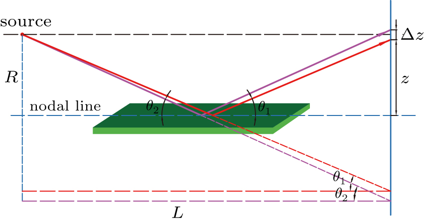
Fig. 1. X-ray imaging geometry for a flat crystal (point source).
Download figure:
Standard imageBy inspection of Fig. 1, we find the following two relations for the Bragg angle θ:

and dθ/d z = cos2 θ/L can be obtained from Eq. (1).
Then, within a single pixel (size a × a) on the detector plane, the divergence angle along the spectral direction is
In the spatial direction, a single pixel on the detector plane has the divergency angle of a/(2R). As a result, a pixel on the detector plane has the solid angle of  . The point source intensity is assumed to be I0 (W/Sr), the crystal diffraction efficiency is η, and the detector respond is ϕ, thus the signal intensity on the detector plane is
As for the von Hamos crystal shown in Fig. 2, similar expressions with Eq. (1) can be found
and dθ/d x = sin2 θ/R can be obtained from Eq. (3).

Fig. 2. X-ray imaging geometry for a von Homas crystal (single cone and point source).
Download figure:
Standard imageSet f(x) = θ = arctan (x/R), and then
So within a single pixel on the detector plane, the divergence angle along the spectral direction is  . It should be pointed out that the divergence angle in the spatial direction depends on the divergence angle of the von Hamos cone as shown in Fig. 2, which is ψ. Then the signal intensity on the detector plane can be written as
For the multi-cone crystal presented in Fig. 3, within a single pixel on the detector plane, the divergence angle along the spectral direction is the same with that of the flat crystal, and the divergence angle along the spatial direction is the same with that of the von Homas crystal. Then the signal intensity on the detector plane is

Fig. 3. X-ray imaging geometry for a multi-cone crystal (single cone and point source).
Download figure:
Standard image3. Surface source hypothesis
The surface source is assumed to be monochromatic with radius r, the total intensity is I0, and I' is the angular distribution of the energy emitted by the surface source, thus I0 = ∫ I' d s. It should be pointed out that the source radius r ≫ a with a as the pixel size on the recording plane.
In the flat crystal case shown in Fig. 4, the image length on the detector plane in the spatial direction is independent of the source size r, because the crystal size is much bigger than the source size r. The image length in the spectral direction on the plane is 2r/cos θ. Since the crystal reflectivity spread is not taken into consideration, the incident x-ray intensity in Δy along the spatial direction on the detector plane is  . According to Eq. (2), the brightness on the detector plane is
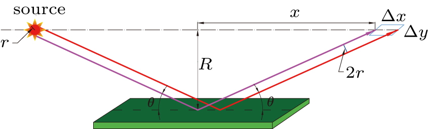
Fig. 4. X-ray imaging geometry for a flat crystal (surface source).
Download figure:
Standard imageIn the von Hamos case shown in Fig. 5, the image area on the detector plane is π r2/sin θ, and the incident x-ray intensity is  . As a result, according to Eq. (4), the brightness on the detector plane is

Fig. 5. X-ray imaging geometry for a von Homas crystal (single cone and surface source).
Download figure:
Standard imageIn the multi-cone case shown in Fig. 6, the image area on the detector plane is π r2/cos θ, and the incident x-ray intensity is  . As a result, according to Eq. (5), the brightness on the detector plane is

Fig. 6. X-ray imaging geometry for a multi-cone crystal (single cone and surface source).
Download figure:
Standard image4. Image size correction
In the application of flat or multi-cone crystal, the position of the detector plane is usually changed to obtain high spectral resolution, wide spectral region, or high focusing intensity. The crystal does not have to be in the center of the source and detector plane. Therefore, the intensity deviation on the detector plane owing to the crystal movement and image size change has to be considered. As can be seen in Fig. 7, we can find
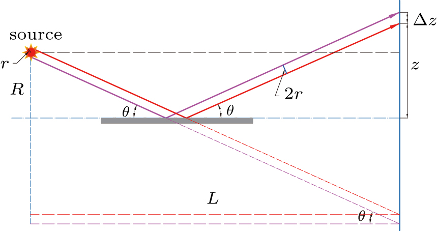
Fig. 7. X-ray imaging geometry for a flat crystal for image size correction.
Download figure:
Standard imageThen the image size on the detector plane is
According to Eq. (6), the brightness on the detector plane in the flat crystal diffraction is
According to Eq. (8), the brightness on the detector plane in the multi-cone crystal diffraction is
5. Discussion
The von Homas and multi-cone crystals are utilized to replace the conventional flat crystal owing to the high x-ray focusing property. Here, the ratio of the diffraction intensity of the von Hamos crystal to that of the flat crystal can be achieved with Eqs. (7) and (10) as
The ratio of the diffraction intensity of the multi-cone crystal to that of the flat crystal can be achieved with Eqs. (11) and (10) as
Given the spectrometer parameters at the Shenguang-III (SG-III) protype laser facility, the radish R of the von Hamos crystal is 11 cm, the distance from the plasma source to the detector plane L = 28.3 cm, the incident Bragg angle θ = 38° for titanium (Ti) He-β line emission (4.75 keV), and the cone divergence angle ψ = 0.55 rad. The α-quartz crystal is adopted and 2d = 0.4256 nm. The source size dependent intensity ratios of Imulti-cone/Iflat and Ivon Hamos/Iflat are calculated and demonstrated in Fig. 8, and a small plasma source leads to a great focusing brightness. The effects of reflectivity spread and mosaic structure are neglected in the model.
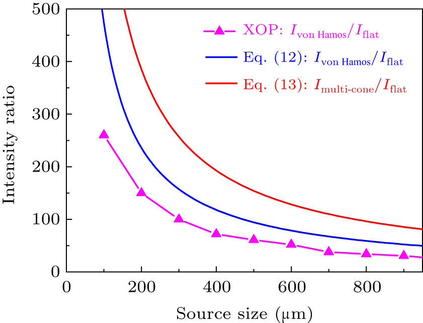
Fig. 8. Source size dependent image intensity of analytical model and simulation data of XOP.
Download figure:
Standard imageTo test the above model, we have applied computer simulations. The code XOP, a widely used public domain software for ray-tracing x-ray optics was used.[19] The simulation data are also shown in Fig. 8. The round source is set from 100 μm to 1000 μm, and the von Hamos crystal of SG-III protype laser facility is adopted, the crystal reflectivity is considered and the mosaic effect is neglected. As shown in Fig. 8, the same trend have been achieved between the analytical and simulated data. The crystal reflectivity spread is calculated in the XOP simulations, and not considered in the analytical model. This leads to the small discrepancy in Fig. 8. In the future experimental applications, the mosaic structure spread should be considered as well.[20,21]
6. Conclusion
This work gives a straightforward solution for the focusing scheme of the flat, von Hamos, and multi-cone crystals. The point source and surface source hypothesises are considered, and the image size effect to the brightness on the detector plane is corrected. This work helps the understanding of the focusing scheme of bent crystals as well as the experimental data analysis and spectrometer design.
Data availability
The data that support the findings of this study are available from the corresponding author upon reasonable request.
Footnotes
- *
Project supported by the National Natural Science Fundation of China (Grant Nos. 11775203 and 12075219) and the ChinaAcademy of Engineering Physics (CAEP) Foundation (Grant No. CX20210019).