

Abstract
We demonstrate the ultra-stable frequency sources aiming to improve the short-time instability of primary frequency standards. These sources are realized by using photonic generation approach, and composed of ultra-stable lasers, optical-frequency-combs, optical signal detecting parts, and synthesizers. Preliminary evaluation shows that the sources produce fixed-frequency at 9.54(/9.63) GHz, 10 MHz, and tunable-frequency around 9.192 GHz with relative frequency instability of 10−15 for short terms.
Export citation and abstract BibTeX RIS
1. Introduction
State-of-the-art primary frequency standards based on cold atoms exhibit quantum projection noise of 10−14@1 s.[1] However, the local oscillator based on quartz-oscillator limits these frequency standards to a level of 10−13@1 s due to the Dick effect[2] in China. Therefore, an ultra-stable frequency source is of prime importance for frequency standards to realize high short-term stability. Moreover, these low-noise frequency sources are also required by other applications, such as ultrahigh resolution radar,[3] deep space navigation,[4] ultrahigh resolution of communications and digital sampling systems,[5] and ultrahigh resolution very-long-baseline-interferometer.[6]
Ultra-stable photonic frequency generation is a natural production of the combination of ultra-stable laser and optical-frequency comb (OFC) techniques.[7–10] The idea of ultra-stable photonic frequency source was proposed just right after the invention of these two techniques.[11] Five years later, scientists at National Institute of Standards and Technology (NIST, USA) realized the first ultra-stable photonic microwave source based on Ti:s OFC.[12] The frequency instability was further improved to 8 × 10⁻¹⁶ for fixed 10 GHz frequency generation in 2011.[13] Actually, the fiber-based OFC exhibits much better reliability than the previous OFC.[14] Consequently, one is inclined to choose fiber-based OFC for the photonic microwave source. With erbium-fiber-based OFCs, scientists at Physics Technology Bundesanstalt (PTB, Germany) and Laboratoire National de Métrologie et d'essais-Systèmes de Référence Temps-Espace (LNE-SYRTE, France) developed the tunable 9.192 GHz photonic microwave sources with the microwave instability of a few 10−15 at 1 s,[15,16] which successfully suppressed the Dick effect of the primary atomic clocks.
In this paper, we demonstrated photonic frequency sources that produce 9.54(/9.63) GHz, 10 MHz, and tunable-frequency around 9.192 GHz with relative frequency instability of 10−15 for short terms.
2. Setup of the photonic frequency source
The setup of the photonic frequency source is shown in Fig. 1. The photonic frequency source is composed of four parts: an ultra-stable laser, an OFC, an optic-to-electronic converter, and a frequency synthesizer. The reference of the frequency source is the length of a 10-cm ultra-stable FP cavity, whose stability ( ) can reach 10−16 level mainly limited by thermal noise of mirrorʼs coating. The general process of realizing an ultra-stable photonic frequency source includes two steps. First, read out the stability of the cavity length by stabilizing a continuous-wave (CW) laserʼs frequency to a resonant mode of the cavity. Second, synthesize the CW laser frequency to the wanted frequencies, which include three phases, i.e., optical frequency synthesizing with OFC, optic-to-electronic conversion and microwave/RF frequency synthesizing.

Fig. 1. (color online) Setup of the photonic frequency source, including ultra-stable CW laser, erbium-doped fiber-based OFC, optic-to-electronic converter, and microwave frequency synthesizer.
Download figure:
Standard imageFor the first part, a 1555 nm CW laser is frequency-stabilized onto the resonant frequency of the cavity by using the PDH technique.[7] The CW laser copies the stability of the cavity length, resulting in a stable frequency source of 193 THz with a relative instability of about 7 × 10⁻¹⁶@1–10 s, details on the ultra-stable laser can be found in Refs. [17] and [18].
The second part is an erbium-doped-fiber-based OFC used as a frequency divider.[19] It is well known that the frequency of an optical combʼs mode (νn) is strictly defined by  , where n is an integer (about a million in this case), fr is the repetition rate of the laser pulses, and fceo is the carrier-envelope-offset frequency. Once fceo is stabilized onto a stable RF reference frequency, the phase relation between νn and fr is fixed. Thus, we can obtain the ultra-stable fr by phase-locking νn to the ultra-stable CW laser. In this experiment, the output average power of the mode-locked lasers is greater than 100 mW with ∼40 nm optical bandwidth. The fceo, with a signal-to-noise rate (SNR) greater than 30 dB at 300 kHz resolution, is detected by an InGaAs photodetector (PD), and picked-up with RF band-pass filters. Details on the optical frequency combs and their performance can be found in Ref. [20].
The third part sketches an optic-to-electronic converter used to detect the laser pulse train from OFC while fr is phase-locked to the ultra-stable CW laser. Additional phase noise of the detected fr signal is mainly contributed by the thermal noise, shot noise, and amplitude-to-phase conversion due to the saturation effect.[21] The corresponding single-sideband phase noise L(f) induced by the thermal and shot noises can be written as[22]
where P0 is the microwave signal power in units of mW, kB is the Boltzmann constant, R is the resistance of 50 Ω, T is the temperature and equal to 300 K, e is the electron charge, and Is is the average photo current (DC). It is worth noting that P0 is proportional to  when the PD is not saturated, and thus L(f) is inversely proportional to Is. Actually, the saturation of the PD is due to charge accumulation in very short time, and determined by the energy of a laser pulse. Thereby we can employ a repetition rate multiplier based on a series of cascaded Mach–Zehnder interferometer (MZI) to obtain a higher saturation Is, which finally reduces the broadband noise floor of the generated microwave signal.[22] With a two-stage MZI, the 41st harmonic of the fr signal near 9.54 GHz with the peak power about −20 dBm is produced by a high speed PD (Discovery DSC30S). The broadband noise floor is below −150 dBc/Hz. As we mentioned, the laserʼs relative intensity noise can result in excess phase noise due to amplitude-to-phase (AM-PM) conversion. In order to reduce this effect, we set the PD input power at about 2.8 mW, corresponding to 3 pJ per pulse. Under this condition, the AM-PM conversion factor for the 9.54 GHz signal is very low due to the balance of the saturation effect.[21] However, we do not actively stabilize the input power, which may lead to noise increase due to power drift.
The last part is a low phase noise frequency synthesizer from the ∼ 9.54 GHz to tunable 9.192 GHz and 10 MHz. Figure 2 shows the scheme of the frequency synthesizer. A 9.6 GHz local oscillator is phase-locked on the 41st harmonic of the fr via back-feeding the error signal, which is obtained by comparing the phases of ∼ 9.54 GHz, the local oscillator frequency, and a tunable frequency produced with a direct digital synthesizer (DDS). We set the local oscillator frequency at 9.6 GHz by tuning the DDS frequency to compensate the frequency difference between the input and the local oscillator. The reference frequency of the DDS is 400 MHz, being generated by frequency-dividing the phase-locked 9.6 GHz signal by 24 times. The 400 MHz signal is also used as the reference frequency of another DDS to control the frequency of the output (9.192 GHz), and it produces a 10 MHz signal by frequency dividing again. All the frequencies are referenced to the 9.54 GHz signal. The tunable 9.192 GHz is the transition frequency of the primary atomic clock (Cs fountain clock), and the 10 MHz is a standard frequency for time signal producing.
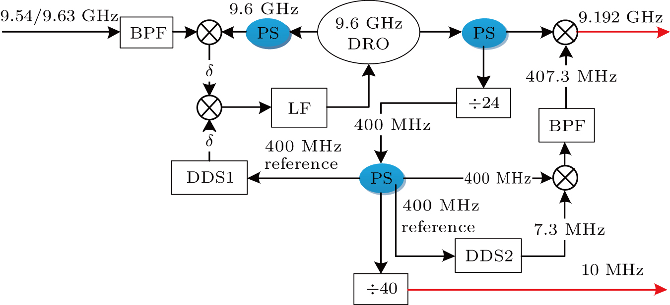
Fig. 2. (color online) Scheme of the frequency synthesizer from 9.54/9.63 GHz to tunable 9.192 GHz. BPF: band-pass filter; LF: loop filter, PS: power splitter; DDS: direct digital synthesizer.
Download figure:
Standard image3. Performance evaluation of the frequency source
To evaluate the performance of such a frequency source, a similar or even better reference system is required. For this reason, we build another independent and identical reference system and perform the measurement shown in Fig. 3.
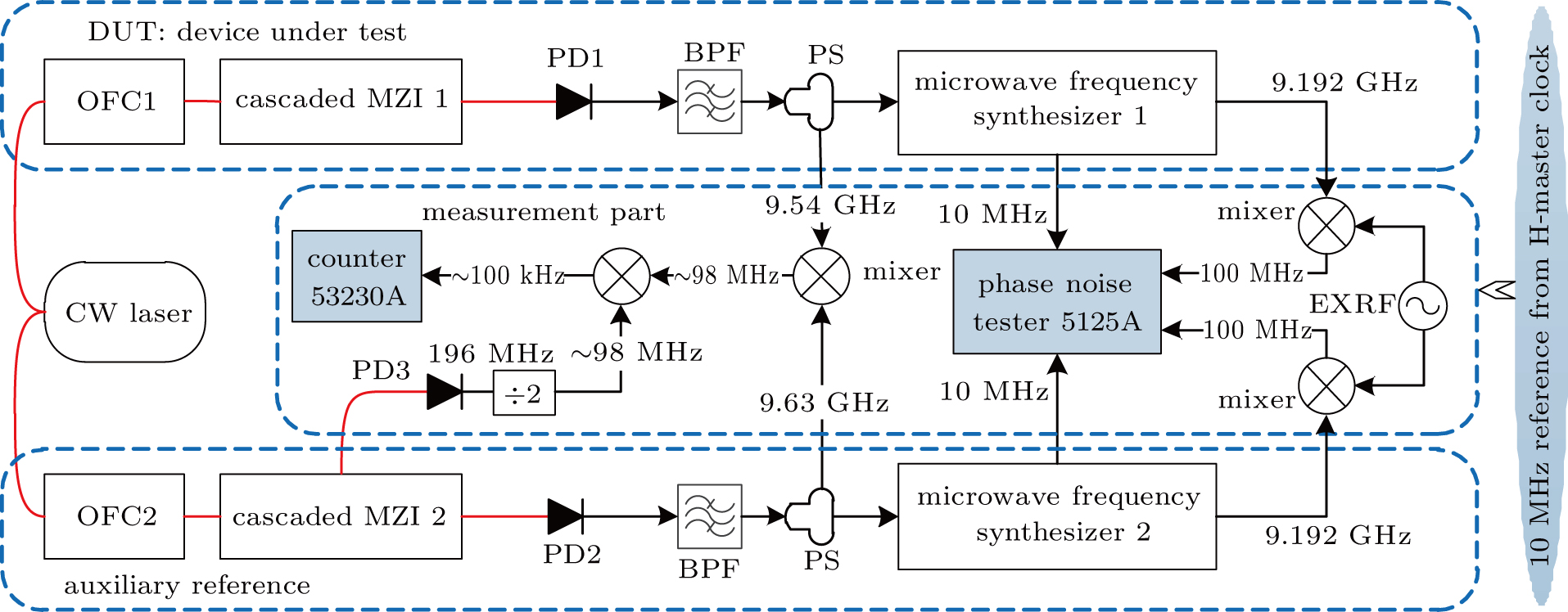
Fig. 3. (color online) Experimental setup for the frequency instability evaluation of the photonic microwave generator. The red solid lines represent optical paths, and the black solid lines represent electrical paths. PD: photodetector; BPF: bandpass filter; PS: power splitter; EXRF: external reference.
Download figure:
Standard imageThe auxiliary reference system includes an OFC with 196 MHz repetition rate, the 49th harmonic of the fr signal detection part, and a frequency synthesizer, which generates a tunable 9.192 GHz and 10 MHz signals from the 9.63 GHz microwave reference, as shown in Fig. 3. Both of the devices under test (DUT) and the auxiliary system are referenced to a common ultra-stable CW laser.
We measure the frequency instability of the microwave/RF signals by comparing the outputs of the DUT and the auxiliary system. The frequency difference of the two optic-to-electronic converters is 98 MHz; the reference (10 MHz) of the Agilent 53230A is provided by an H-master clock with frequency instability of 10−13@1 s. Thus, the measurement noise floor is at the level of 10−12@1 s if we directly evaluate the 98 MHz signal. To improve the equivalent measurement noise floor, we mix it down to about 100 kHz with half fr of the auxiliary OFC. Then the relative frequency instability is evaluated by calculating the Allan deviation of the 100 kHz signal normalized with 9.54 GHz. We record the frequency fluctuation of tunable 9.192 GHz and 10 MHz with a phase noise tester 5125A as shown in Fig. 3. For the 10 MHz signal, the phase noise is measured to be −130 dBc/Hz@1 Hz, being attributed to the electronic flicker noise introduced by the frequency divider.
The relative frequency instabilities of the photonic frequency source are shown in Fig. 4. For the frequency synthesizers, the frequency stability from 193 THz to 9.54 GHz is about  @1 s, the frequency stability from 9.54 GHz to tunable 9.192 GHz is
  @1 s, and the frequency stability from 9.54 GHz to 10 MHz is about
  @1 s. Since the CW laser, OFC, and synthesizers are independent, we believe that their noises are not inter-related, i.e., the instability of the generated frequency signal is square root of their square sum. In this way, we estimate the relative frequency instability of the tunable 9.192 GHz and 10 MHz to be
  @1 s and
  @1 s, respectively. Obviously, the synthesizer-introduced noises limit the performance of the generated signals, because lots of parameters are not well optimized, including gains and cross-talks of phase-locked-loops, environmental noise, electronic noises. However, it is the first room temperature microwave/RF oscillator producing frequency signals at 10−15 level in China, to the best of our knowledge. Its frequency stability matches the requirement (below
  @1 s) of the primary frequency standards.
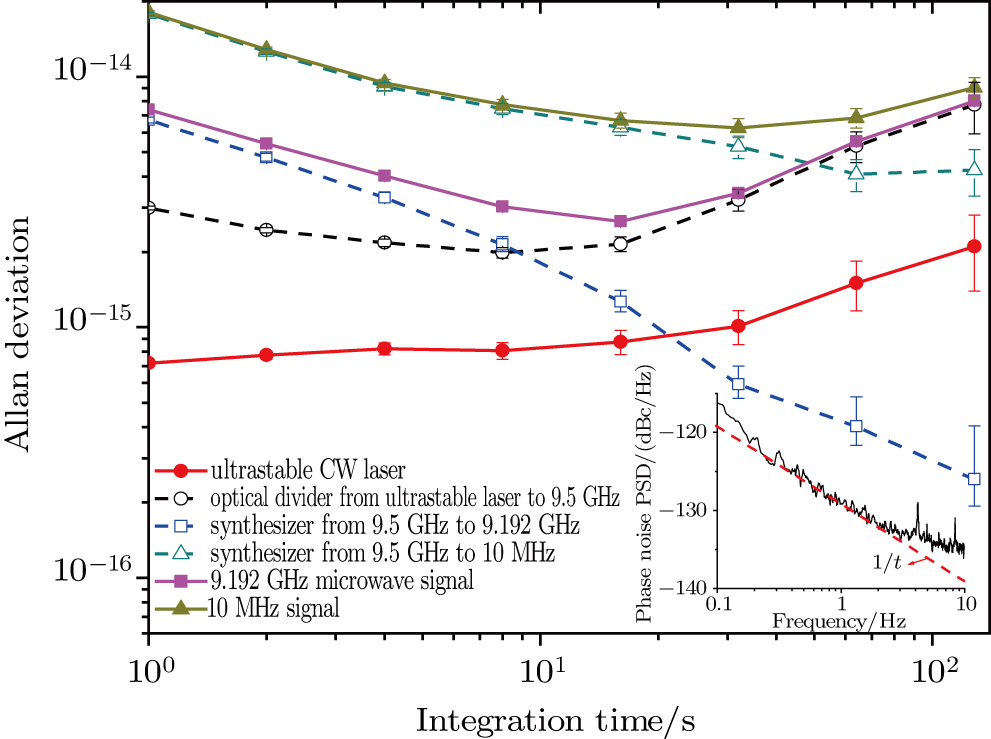
Fig. 4. (color online) The relative frequency instability characterized by the Allan standard deviation. Red solid circles: independent ultra-stable CW laser at 1555 nm given by Ref. [17]. Black empty circles: optical frequency synthesizer from 193 THz (1555 nm laser) to 9.54/9.63 GHz. Blue empty squares: microwave synthesizer from 9.54/9.63 GHz to tunable 9.192 GHz. Dark cyan empty triangles: synthesizer from 9.54/9.63 GHz to 10 MHz. Magenta solid squares: tunable 9.192 GHz. Dark yellow solid triangles: 10 MHz signal. The insert shows phase noise of 10 MHz signal.
Download figure:
Standard image4. Conclusion
We have demonstrated a photonic microwave generation source, where an Er:fiber-based optical frequency comb is phase locked to an ultra-stable CW laser with a relative frequency instability of  @1 s. The frequency instability of the fixed 9.54 GHz microwave signal is
  @1 s, the frequency instability of the 10 MHz signal is about
  @1 s, and the frequency instability of the synthesized 9.192 GHz signal is about
  @1 s and below
  @20 s. Benefiting from such a stable frequency source, the short-term frequency instability of the cesium fountain clock can be improved from a few
  to a few
  limited by quantum project noise.
Acknowledgment
The authors would like to thank special funds for scientific equipment development (YZ201518) from Chinese academy of sciences for the use of the developed equipment.
Footnotes
- *
Project supported by the National Natural Science Foundation of China (Grant Nos. 91536217, 61127901, and 11775253) and the Youth Innovation Promotion Association of the Chinese Academy of Sciences (Grant No. 2015334).