Abstract
Microelectromechanical systems (MEMS) based ring shaped resonators usually have a ring supported by spoke shaped springs. In this paper, we developed a general analytical model that can determine the natural frequency of any MEMS ring resonator considering effective mass and stiffness of spokes in both radial and tangential displacements. Our model is also able to determine the stiffness of the circular curved beam with arbitrary central angle. The well-known energy based Castigliano's method was used to calculate the stiffness of a circular curved beam considering both flexural and axial rigidities. The stiffness of a circular curved beam with different central angles was determined and compared with the literature and finite element method (FEM). The results show that for the case of a central angle of the curved beam larger than 60 degrees, the deviation between the FEM and analytical approach is less than 1%. The potential energy and kinetic energy of the outside ring and spokes were determined based on the displacement function. The natural frequency of a ring resonator with different number of circular curved beams in the form of petals in modes n = 2 and n = 3 were determined and the results were compared with a numerical approach using FEM. The deviations between the analytical approach and numerical method are less than 4%.
Export citation and abstract BibTeX RIS

Original content from this work may be used under the terms of the Creative Commons Attribution 4.0 licence. Any further distribution of this work must maintain attribution to the author(s) and the title of the work, journal citation and DOI.
1. Introduction
Microelectromechanical systems (MEMS)-based vibrating structures are used as the main sensing element in many inertial sensors, including gyroscopes [1]. In these types of sensors, a vibrating mass is supported by microscale spring-like structures. Compared to large-scale mechanical gyroscopes, the microscale Coriolis vibratory gyroscope (CVG) has no moving parts, is simple to fabricate, has a short run-up time, needs low power, and generates low noise [2]. The main idea to use CVG was to replace a continuously spinning rotor with a vibrating mass [3] in which the Coriolis force is induced on a vibratory mass and creates the degenerate mode of vibration. This motion produces a DC voltage proportional to the rate of rotation [4].
The vibrating mass in the micro CVGs can be in the form of beams, rings, disks, or 3D shells, and 3D hemispherical resonator gyroscopes (HRGs), among which HRGs are the best performing CVGs [5, 6]. Motivated by the model of operation of HRGs and the difficulties in fabrication of a symmetric hemispherical structure at the microscale, the next generation of micromachined gyroscopes in the form of a ring [7], which is a simplified form of HRG [8], has been propelled to inherit the advantages of HRGs [6]. Perfect symmetry, insensitivity to the environment, better shock resistance, and mass production with better performance make vibratory ring gyroscopes a better choice in which an elastic ring works as a resonator [6, 9, 10]. In addition, the vibrating ring gyroscope (VRG) makes full use of having all the vibratory energy in one plane [11].
The inertia force due to the vibration of the CVG is generated on mass elements, called the proof mass. This oscillatory motion of the proof mass is called the drive mode. Due to the induced Coriolis force on the mass elements because of the rotation of the CVG, the mass rotates and oscillates orthogonal to the drive mode, which is called the sense mode [3]. In a perfectly symmetric mode matched CVG, there is no frequency split between these two modes of vibration. Any mismatch between these frequencies leads to bias stability, which is the deviation of the sensor from its mean value of the output rate. HRG and ring resonators, which are called wine-glass resonators, are the most promising design forms due to their excellent modes matching [12].
Ring resonators consist of one or more continuous or intercostal rings supported by internal or external structures were used. The rings are free to deform and displace in-plane; however, undesirable out-of-plane deformations/displacements should be minimized. The early ring gyroscope fabricated by metal electroforming was reported in [13]. It consists of a ring with a rectangular cross section and eight internal supporting beams in the form of a semicircle connected to a centre stem. Later, much research works reported understanding the dynamic behaviour of ring resonators and proposed various ways to support the ring to the anchor. Hopkin [11] and Hopkin et al [14] fabricated a silicon ring resonator supported with eight outer radial spokes anchored to a frame. He and Najafi [15] reported a ring resonator with eight meander-shaped (folded-shaped) inner supporting beams. Weng et al [8] fabricated a ring resonator with eight externally supporting rings connected to an octagonal frame.
The main design variations revolved around finding different ways to support the ring to improve frequency symmetry, sensitivity, energy loss, and displacement. Gallacher et al [16] designed a ring resonator with eight small inner supporting U-shape beams and eight rectangular masses connected to the ring. Hu and Gallacher [17] proposed a ring resonator with eight pairs of Z-shape inner support legs connected to a circular centre stem. Chen et al [18] reported a ring resonator with sixteen outer beams in the form of S- and L-shapes. Zhou et al [19] improved the mechanical sensitivity of a resonator in the form of concentric rings by optimizing the thickness distribution of rings. Zhou et al [20] tuned modal coupling in a ring resonator with dynamic electrostatic fields. Kim and Kim [21] analytically studied the thermoelastic damping of a ring resonator without any inside beams. Hossain et al [22] studied the thermoelastic damping of ring resonators. They discussed the geometry of three ring resonators, including Putty's work [13] with sixteen spokes instead of eight [11, 17]. Yoon et al [23] and Cao et al [10] fabricated a ring resonator supported by eight double U-shaped (capsule-shaped) beams connected to a central circular stem. Kou et al [24] designed S-shaped beams, Bai et al [25] designed tee-shaped beams, and Xiao et al [26] designed honeycomb-shaped beams. Khan et al [27] designed and fabricated a new ring resonator with a solid anchor and four supporting beams in the form of petals. Some resonators are built with more than one ring. Senkal et al [28] reported a new toroidal ring gyroscope with an outer anchor ring and inside concentric rings used as resonators. Sun et al [29] designed a novel ring resonator in the form of two intercostal concentric rings connected by twelve H-shape beams to a disk anchor.
While various support and ring arrangements have been developed as reported above, the free vibration analysis of the resonator is necessary to evaluate the natural frequency. In contrast to many mechanical systems and structures in which resonance should be avoided, in vibratory gyroscopes, the natural frequency is the desired working frequency. The vibration of a free ring without supporting beams has been studied extensively both theoretically [30] and experimentally [31]. Some research has determined the natural frequency of a ring resonator with a special configuration of spokes. To the best of our knowledge, a detailed analytical study of the vibration of a ring resonator with circular curved beams has not been performed. Therefore, the aim of the present work is to derive an equation for calculating the stiffness of a circular curved beam. Such an analytical model approach can assist the designer to optimize their resonator for desired frequencies. The energy based Castigliano's method is used to calculate the compliance coefficients of a circular curved beam considering both flexural and axial rigidity. The finite element method (FEM) is used to compare the results. The frequencies of a ring resonator with circular curved beams are calculated using the derived equation of stiffness and effective mass and compared with the FEM to show the effectiveness of the proposed method that can be used as a baseline model tool for designing curved beam-shaped spring-supported resonators.
In the following section, the kinetic and potential energy of a ring and spokes are studied using the displacement function of a ring in both radial and tangential direction, followed by equation of motion and natural frequency analysis. In the next section, the compliance coefficient of a circular curved beam in any arbitrary direction is derived, and a closed-form equation for calculating the stiffness of a circular curved beam in the general direction neglecting axial rigidity is given. In section four, the frequency of a ring resonator with different numbers of inside beams (petals) is determined and compared with the numerical method. The conclusion is presented in the last section.
2. Vibration analysis of a ring
Ring resonators consist of an outside ring with inside beams, called spokes (figure 1). Spokes are positioned symmetrically and can be in the form of folded beams or arches. Single anisotropic crystal silicon (SCS) with crystal orientation of 〈100〉 is widely used material for fabrication of MEMS resonator [6, 32, 33] due to accuracy and low cost of fabrication. However, anisotropy in the stiffness, generate frequency split [34] and coupling of degenerate modes [35]. To overcome this, either isotropic material with symmetry geometry or anisotropy material with optimized asymmetry geometry is used [6] such as, adjusting position of spokes [34], adjusting width of spokes [33, 34], varying width of ring [33, 34], angle adjustment of inner spokes [34], combining the ring resonator and disk resonator with appropriate ratio [32], use of ellipse spoke in a multi ring resonator [32], and using electrostatic spring softening stiffness [35]. In this study, a symmetry ring resonator build from isotropic material with four, six and eight spokes in the form of petals (figure 1) is studied.

Figure 1. The ring resonator with circular curved beams considered in this study.
Download figure:
Standard image High-resolution image2.1. Displacement functions of a ring in the radial and tangential directions
Assuming small deflection theory, which is valid in vibration of shells/rings when the amplitude is less than thickness of shell, the strain components in the polar coordinate system are expressed as follows [36]:


where,  and
and  are polar coordinate system (figure 1),
  and
and  are the displacement functions in the radial and tangential directions, respectively and
  and
and  are the radial and tangential components of the normal strain. Assuming pure bending of the ring without any stretching, yield to:

The radial displacement of the ring can be expressed in the form of a trigonometric series [37] as follows:

where  and
and  are amplitudes of the n-th mode of vibration. Substituting equation (4) in equation (3) yields the following equation of the displacement function in the tangential direction:

2.2. Kinetic energy of the outside ring
Vibration of a system involves an alternating interchange of potential energy to kinetic energy and vice versa [38]. Thus, any vibrating system must have a mass to store kinetic energy and a spring to store potential energy [38]. The velocity components of any particle on the ring are as follows:


The velocity vector of any point on a non-rotating ring is as follows:

where, and  and
and  are unit vectors in the radial and tangential directions, respectively. With the velocity of a particle on the ring the kinetic energy is calculated as follows:

where,  is the total mass of the ring. Substituting equations (6) and (7) in equation (9) yields the equation of kinetic energy of the ring as follows:

2.3. Potential energy of the outside ring
The potential energy of a beam due to bending without extension is as follows:
where E is Young's modulus,  is the moment of inertia with respect to the rotation axis, and
  is the curvature. In the case of a circular beam,
  is replaced with the change in the curvature as follows [37]:
where,  is the radius of the ring. Thus, the potential energy of the outside ring is:

2.4. Kinetic and potential energy of the spokes
If we assume effective mass of each spoke as a lumped mass located at a point on the ring, with velocity of the ring, the kinetic energy of the spokes is calculated as follows:

where,  and
and  are the effective masses of one spoke when vibrates in the radial and tangential directions, respectively and
  is the number of spokes. Substituting equations (6) and (7) into equation (12), the kinetic energy of the spokes would be:

where,  is the angular orientation of the i-th spoke in respect to x axes (figure 1).
The potential energy of spokes is determined as follows:

where,  and
and  are the stiffness of one spoke in the radial and tangential directions of the outside ring, respectively. Substituting equations (4) and (5) into equation (14), the potential energy of the spokes would be:

2.5. Equation of motion
Neglecting damping, the equation of motion using the well-known Lagrange's method [39] expressed as follows:

where,  and
and  are the kinetic and potential energy of the ring,
  and
and  are the kinetic and potential energy of spokes. Substituting kinetic and potential energy of the ring and spokes, the equations of motion of the ring resonator are determined as follows:

where,  is the mass matrix and equals to:
 is the stiffness matrix:
2.6. Natural frequency of non-rotating ring
The natural frequency equation of a non-rotating ring is determined as:

The equation for calculation of natural frequency is simplified as:
To investigate the effect of tangential displacement of the outside ring on natural frequency, neglecting the tangential displacement of the outside ring is, the natural frequencies are determined as follows:

3. Stiffness of a circular curved beam
The circular curved beams in a ring resonator are connected at one end to the anchor and at the other end to the outside ring. Due to the oscillatory motion of the outside ring, the connection point of the beams to the ring is displaced with the ring. In the first mode of vibration of the ring, the rocking mode, depending on the position of the beam, it displaces in different directions. Thus, it is necessary to have stiffness of the spokes are free to move in any arbitrary direction (figure 2).
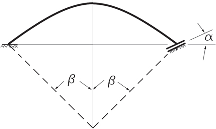
Figure 2. A circular curve beam fixed at one end and free to move in any arbitrary direction at the other end, 
Download figure:
Standard image High-resolution imageTo calculate the stiffness of a circular curved beam, the energy-based method is employed, and the compliance coefficients considering both flexural and axial rigidity of the curved beam are calculated (appendix). To study the effect of axial rigidity on the stiffness of circular curved beams, the stiffness of some curved beams with different central angles is determined for different values of the ratio of the width of the beam to the radius of the beam (figures 3–4).

Figure 3. Stiffness of a semicircle curved beam ( ) as a function of direction free to displace,
Download figure:
Standard image High-resolution image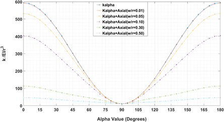
Figure 4. Stiffness of a circular curved beam (2β = π/3) as a function of direction free to displace, 
Download figure:
Standard image High-resolution imageAs seen, for the case of a semi-circular curved beam, neglecting the axial rigidity is justified for the calculation of stiffness. For example, for the case of a ratio of beam width over radius of 0.5, the maximum deviation is 10%, which occurred for stiffness calculation in the direction of the chord line ( or 180 degrees).
Comparing figures 4 and 3, it can be concluded that by decreasing the central angle of circular curved beams, neglecting the axial rigidity for the calculation of stiffness in the direction of the chord line when the ratio of beam width to beam radius is larger than 0.1, is not justified; however, neglecting this rigidity for the calculation of stiffness in the direction perpendicular to the chord line is justified regardless the ratio of beam width to radius.
To validate the stiffness calculation of circular curved beams, the finite element simulation software ANSYS v.2022 R1 [40] was used using solid elements, SOLID185, which has eight nodes with three degrees of freedom at each node. A fixed boundary condition at one end is imposed by restraining all degrees of freedom of all nodes. The other end is free to slide only in the direction of  thus, degrees of freedoms in the direction of
  and z are restrained, and in the direction of
  all nodes are coupled. Young's modulus is selected as
  Pa, and Poisson's ratio is selected as 0.22. A unit load is applied in the direction of
  and the displacement in this direction is determined. The stiffness of the circular curved beam is the reverse of the displacement (figure 5).
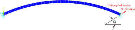
Figure 5. Finite element model of a circular curved beam, clamped at one end, and free to move only in the direction of  at the other end.
Download figure:
Standard image High-resolution imageFigure 6 depicts the stiffness of a circular curved beam with the ratio of beam width over beam radius of 0.011, in the direction of the chord line for different values of central angle which are compared with equation (A.8) for both cases of considering/neglecting axial rigidity. The results show that the deviation between the current study and FEM for both cases of considering/neglecting axial rigidity is less than 1% for a central angle larger than 60 degrees. For the central angle of 40 degrees, there is an approximately 9% deviation between the results of the FEM and equation (A.8) neglecting axial rigidity and approximately 6% deviation considering axial rigidity. Additionally, when  is larger than 50 degrees, neglecting axial rigidity leads to less than 1% deviation. Thus, for a small ratio of beam width to beam radius and a large value of central angle, neglecting axial rigidity is justified since in this case, deflection of the beam is mostly due to bending moment rather than axial force. However, for a central angle of the arch less than 30 degrees neglecting axial rigidity yields inaccurate results since in this case, the displacement of the beam in the direction of the chord line is mostly due to axial force rather than bending.
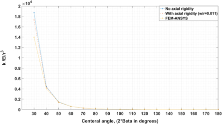
Figure 6. Stiffness of a circular curved beam in the direction of chord line, 
Download figure:
Standard image High-resolution imageUsing compliance coefficients (appendix), the stiffness of a circular curved beam with a central angle of  in the direction
  with respect to the cord line and neglecting the axial rigidity is determined as follows:

For example, in the case of  in which the supporting beam is in the form of a semicircle, the equation is simplified as follows:

and for the case of  the stiffness is equal to:

which is the same as equation (11) of Li et al [41]. For the case of  the stiffness equal to:

which is the same as equation (11) of Li et al [41] and Eq. (38) of Yoon et al [42]. For the case of  , the stiffness is equal to:

which is the same as equation (39)f Yoon et al [42], and equation (11) of Li et al [41].
Figure 7 depicts the variation in the stiffness of a semi-circle curved beam as a function of direction free to displace,  As seen,
  is zero for
  0, thus, the x- and y-axes are the principal axes of a circular curved beam.

Figure 7. Stiffness of a semi-circle curved beam ( ) in different direction as a function of direction free to displace, α.
Download figure:
Standard image High-resolution image4. Results and discussion
Different types of supporting beams are proposed for ring resonators. To demonstrate the applicability of equations for calculation of natural frequency of a ring resonator with circular curved beam, a ring resonator with different number of circular curved beams in the form of a petals (figure 1) is considered. The dimensions of the spokes and ring are depicted in table 1.
Table 1. Geometrical and mechanical parameters of the ring resonator considered in this study
Young's modulus, single crystal Silicon, 
|

|
Density, 
| 2329 
|
Anchor Radius, 
| 100 
|
Ring radius (mean), 
| 615 
|
Ring width, 
| 30 
|
Ring thickness,
| 60 
|
Spokes radius (mean), 
| 450 
|
Spokes width, 
| 5 
|
Spokes thickness, 
| 40 
|
Central angle of spokes, 
| 67.5 deg. |
4.1. Natural frequency analysis using numerical method
The finite element simulation tool ANSYS is used to analyse free vibration of a ring resonator. Solid element, SOLID185, is used and fixed boundary conditions are applied at the perimeter of the anchor to exclude it from vibration. Figures 8–10 depict the mode shapes of the considered ring resonator in the n = 2 and n = 3 modes of vibration with eight, six and four spokes in the form of petals.

Figure 8. Natural frequency in n = 2 and n = 3 modes of vibration of the ring resonator (table 1) with eight petals.
Download figure:
Standard image High-resolution image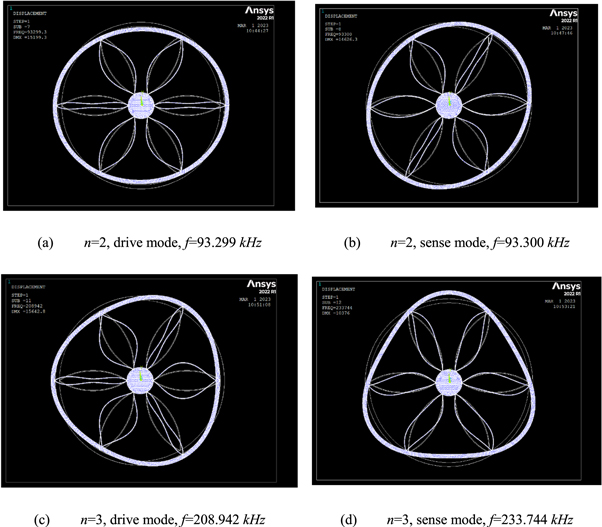
Figure 9. Natural frequency in n = 2 and n = 3 modes of vibration of the ring resonator (table 1) with six petals.
Download figure:
Standard image High-resolution image
Figure 10. Natural frequency in n = 2 and n = 3 modes of vibration of the ring resonator (table 1) with four petals
Download figure:
Standard image High-resolution image4.2. Natural frequency analysis using analytical approach
To calculate natural frequency of a ring resonator, it is necessary to have the effective mass and stiffness of the spokes. The stiffness of one circular curved beam in the direction of the chord line with and without axial rigidity are calculated using equation (A.8) and equation (21) and compared with FEM (table 2).
Table 2. Stiffness of a circular curved beam ( ) in radial and tangential direction of ring resonator for the case of,

 and
and 
| Method | Neglecting axial rigidity | Considering axial rigidity | ||
|---|---|---|---|---|

|

|

|

| |
| Analytical | 259.18 | 6.121 | 258.27 | 6.116 |
| FEM |

|

| 259.40 | 6.108 |
| Deviation |

|

| 0.4% | 0.1% |
As seen, the results of FEM are very close to analytical approach, and neglecting axial rigidity due to low value of the ratio of beam width over beam radius is justified.
To determine the effective mass of circular curve beam in the radial and tangential directions, modal analysis of one beam when it is free to vibrate using FEM is carried out, and the frequencies are determined in the radial and tangential directions as,  and
and  respectively.
Natural frequencies of the drive and sense modes of vibration of the ring resonator with eight, six and four spokes considering/neglecting tangential displacements of the outside ring are determined and compared with FEM (table 3).
Table 3. Frequency of the ring resonator (table 1) with different number of spokes.
| Number of spokes (number of curved beams) | Method | n = 2, mode | n = 3, mode | ||||
|---|---|---|---|---|---|---|---|
| Drive mode (kHz) | Sense mode (kHz) |
 (Hz) (Hz) | Drive mode (kHz) | Sense mode (kHz) |
 (Hz) (Hz) | ||
| 8 (16) | equation (19) | 97.582 | 97.582 | 0 | 214.606 | 214.606 | 0 |
| equation (20) | 98.763 | 98.763 | 0 | 217.172 | 217.172 | 0 | |
| FEM | 95.784 | 95.781 | 3 | 215.091 | 215.091 | 0 | |
| 6 (12) | equation (19) | 97.827 | 96.092 | 1735 | 213.781 | 231.694 | 17913 |
| equation (20) | 98.854 | 97.279 | 1575 | 213.782 | 236.288 | 22506 | |
| FEM | 93.299 | 93.300 | 1 | 208.942 | 233.744 | 24802 | |
| 4 (8) | equation (19) | 98.763 | 82.386 | 16377 | 225.896 | 225.896 | 0 |
| equation (20) | 98.763 | 83.520 | 15243 | 227.215 | 227.215 | 0 | |
| FEM | 95.879 | 83.630 | 12249 | 224.358 | 224.358 | 1 | |
As seen, though the deviation between FEM and analytical approach neglecting tangential displacement of the outside ring is insignificant, however considering tangential displacement of the outside ring for calculation of the effective stiffness and effective mass of spokes, has reduced the deviations between FEM and analytical approach. Additionally, it is seen that the ring resonator with eight spokes has the best performance since it has the least frequency split in both n = 2, and n = 3 modes of vibration.
If one neglects the mass and stiffness of the spokes the natural frequency of the ring resonator would be as follows:

which is the same as that given by [37, 42]. The results of equation (26) for n = 2 mode of vibration is  and for n = 3 mode of vibration is
  Thus, neglecting the stiffness and mass spokes for this ring resonator underestimate the frequency in n = 2 mode of vibration and overestimate the frequency in n = 3 mode of vibration.
5. Conclusion
In this study, the dynamic performance of a MEMS ring resonator with supporting beam configurations in the form of circular curved beams was investigated. The potential energy and kinetic energy of the outside ring and circular curved spokes are determined based on the displacement function of a ring neglecting tangential extension. With the kinetic energy and potential energy, the effective mass and stiffness of the outside ring were determined. The well-known energy based Castigliano's method was used to calculate the stiffness of a circular curved beam considering both flexural and axial rigidity when the beam is fixed at one end and free to slide in one arbitrary direction at the other end. The stiffness of a circular curved beam with different central angles and different sliding directions was determined and compared with the literature and FEM, and very good agreements were observed. Comparing the stiffness of circular curved beams with and without axial rigidity, it is found that neglecting axial rigidity in the calculation of stiffness in the direction perpendicular to the chord line is justified regardless of the value of the central angle; however, in the direction of the chord line, it is not justified for a large ratio of beam width to beam radius and for a small value of the central angle of the beam. The natural frequency of a ring resonator with different numbers of circular curved beams in the shape of a petal in n = 2 and n = 3 modes of vibration were determined with and without considering tangential displacement of the outside ring and compared with the FEM. The results show that deviation between FEM and analytical approach neglecting tangential displacement of outside ring is less than 4%. Additionally, the results show that the frequency split of a ring resonator with eight petals are the least for both n = 2, and n = 3 modes of vibration. The performance of a MEMS resonator also depends on the electrode configuration especially when applied as an inertial sensor. Optimizing the electrode arrangement is important for electrostatic actuation, sensing, frequency tuning and mode shaping. The arrangements of the electrodes, gap distance between electrodes and resonator, and configuration of the applied voltage could be investigated in the future by extending the analytical model presented in this paper. The analytical model presented in this paper can serve as a basis for designing a ring resonator and further aid the development of high-performance MEMS, and in particular rings designed with circular curved beam.
Acknowledgments
The authors would like to thank NSERC (Natural Sciences and Engineering Research Council) Discovery Grant Program (RGPIN-2023-03423) for financial support. The authors thank CMC (Canadian Microelectronics Corporation) Microsystems for CAD tools support.
Data availability statement
All data that support the findings of this study are included within the article (and any supplementary files).
Appendix
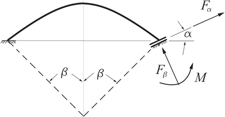
To calculate the stiffness of a part of the circle in the general direction  (figure A.1), the energy-based method of Castigliano is used.
Figure A.1. A circular curved beam fixed at one end and free to displace in the direction of 
Download figure:
Standard image High-resolution image
The bending moment at any cross section of the partial circle is defined as:

and the displacements of the free end of the partial circle are calculated as follows:


where  and
and  are displacements of the spring at the free end in the
  and
and  directions, respectively
  is the rotation of the free end around the
  axis,
axis,  and
and  are the applied forces at the free end in the
  and
and  directions, respectively, and
  is the applied bending moment around the z-axis at the free end. Substituting the bending moment in equations (A.2) to (A.4) yields the following relations for calculating the displacements:


Equations (A.5) to (A.7) can be expressed as follows:
where  are the compliance coefficients of the spring and are determined as follows:


Thus, the stiffness of the spring in the  and
and  directions is defined as: