


Abstract
Quantum electrodynamics (QED) is a foundation of modern physics, yet access to the strong-field QED regime in the laboratory remains a formidable challenge. Currently, high-power lasers at the multi-petawatt level and above are generally believed to be an important approach to test QED physics. Here, we present a different approach by use of an electron beam self-pinched to near-solid-density. The beam self-pinching is realized while it transports through a properly designed hollow cone target, where strong azimuthal magnetic fields are generated by the beam-induced plasma return currents at the inner surface of the cone target. In this way, the beam diameter can be reduced by more than an order of magnitude down to submicron and its density is increased by hundreds of times. The produced ultradense electron beams can unlock a new regime of QED-dominated beam–plasma interactions, for example, more than 60% of the beam energy can be converted into GeV gamma-rays with unprecedented brilliance when such a beam passes through a thin solid foil. Moreover, with proper parameter design, this beam-focusing scheme can also be applied to positron beams and thus may find applications in broad areas, such as particle colliders and strong-field physics.
Export citation and abstract BibTeX RIS

Original content from this work may be used under the terms of the Creative Commons Attribution 4.0 license. Any further distribution of this work must maintain attribution to the author(s) and the title of the work, journal citation and DOI.
1. Introduction
Quantum electrodynamics (QED) is a successful theory and has laid a foundation for modern physics, but its strong-field regime remains elusive. The importance of strong-field QED can be characterized by the quantum parameter [1, 2]  , where
  is the Schwinger field [3],
  is the reduced Planck constant,
  is the electron mass,
  is the elementary charge,
  is the electron relativistic factor,
  is the speed of light in vacuum, and
  is the electric field perpendicular to the electron velocity
  . When
  approaches unity, both strong radiation reaction and quantum effects become prominent, where a large amount of electron energy can be converted into high-energy photons. Under such conditions, the dynamics of physical systems will be profoundly altered [4, 5], which could create a new class of QED-dominated plasma states. Such plasma states could be relevant to some extreme astrophysical phenomena or environments, such as gamma-ray bursts [6], pulsar magnetospheres [7], and black holes [8].
The interaction of ultrarelativistic particles with intense electromagnetic fields of ∼1011V m−1 generated in crystals provides an approach for studying QED effects [9]. For example, experimental observation of quantum radiation reaction was made at the European Organization for Nuclear Research (known as CERN) using a 180 GeV positron beam in aligned crystals [10]. Because existing accelerators are unable to deliver lepton beams at higher energies, it is difficult to extend this approach to larger  or more extreme QED regime in the foreseeable future. Several promising interaction configurations have been proposed to access to the strong-field QED regime by use of energetic electron beams, which collide with intense laser pulses [11, 12] or interact with some structured solid targets [13–15]. Significant progress in high-power laser technology [16] provides new opportunities to explore such high-field physics, see [1, 2, 17] and references therein. The most common way to study strong-field QED is based upon the head-on collision of an intense laser pulse with a high-energy electron beam, which was first demonstrated at the Stanford Linear Accelerator Center in the famous E144 experiment [18, 19], attaining
  . Recently, this configuration has also been verified using an all-optical method of laser-wakefield-accelerated electron beams [20, 21], which gives
  . However, these schemes are very sensitive to the space-time alignment precision of the electron beam and laser pulse, and rely heavily on the beam and laser parameters. Higher intensity laser pulses and/or higher energy electron beams are required to realize larger
  [22–24]. Besides, laser prepulse and relativistic ion effects become prominent at high intensities above 1022 W cm−2, which may affect these schemes. Hence, implementing these schemes in high-field regime is quite challenging.
Here, we introduce a scheme by use of a high-current electron beam only. It is realized via the self-pinching of high-current beams down to the submicron level by use of a properly designed cone target, so that the beam density can be enhanced by more than two orders of magnitude up to the solid density. This beam self-pinching scheme is also applicable for positron beams and thus opens the door to new avenues of dense beam-based research. For instance, when such a dense electron beam is injected into a solid target, the induced transverse fields inside the target are high enough to trigger QED effects and generate bright γ-rays with high efficiency. A collimated γ-ray beam with high density and submicron size is produced, making the source brilliance several orders of magnitude higher than that obtained with multi-petawatt high-intensity lasers [25–31].
2. Results
2.1. Physical scheme
In general, collimation and focusing of energetic electron beams are achieved by use of conventional magnetic devices. However, this technique has several drawbacks such as low field gradients, large sizes, slow switching times, and transverse asymmetry. These make it unsuitable for focusing high-current electron beams with large divergence and small size. Laser-wakefield acceleration from plasma [32] is a promising candidate for next-generation compact accelerators [33] and light sources [34], where the resulting electron beams typically have a few microns in size, several milliradians in divergence and hundred-kA-class currents, making it difficult to focus or collimate and transport them during applications. To address this problem, considerable efforts have been dedicated to developing novel types of focusing elements (e.g., plasma lenses) [35–38], which can provide the field gradients several orders of magnitude larger than quadrupole magnets. Many applications can benefit greatly from a well-focused relativistic electron beam, for instance, multistage plasma-based accelerators [39, 40], compact free-electron lasers [41–43], synchrotron radiation sources [44–46], brilliant betatron x-rays [47], and effective laser-Thomson scattering [48, 49]. Despite significant progress made in the last few decades, there is no applicable way to focus relativistic high-current electron beams down to the submicron scale.
To tackle the challenges of high-current beam focusing and high-field QED testing mentioned above, we propose a completely different approach by use of a properly designed hollow cone target; see figure 1(a). We demonstrate the scheme using three-dimensional (3D) particle-in-cell (PIC) simulations (see section 2.2 for details). As the high-flux electron beam traverses the cone target, ultra-intense return currents are formed to create gigagauss-scale magnetic fields that radially focus the beam inwards, so that the beam diameter is reduced by about an order of magnitude to the submicron scale, as shown in figures 1(b) and (c). Accordingly, the beam density can be increased hundreds of times, approaching the solid density. Such dense beam may enable a novel regime of radiation-dominated beam–plasma interaction and pave the way for future compact ultrabright γ-ray sources.

Figure 1. Concept of relativistic charged particle beam focusing. (a) Schematic of relativistic high-flux particle beam pinching in a hollow cone. Illustration of this scheme from a 3D particle-in-cell simulation at the beginning (b) and end (c) of the hollow cone.
Download figure:
Standard image High-resolution image2.2. Numerical simulation
To demonstrate the proposed scheme, 3D simulations with the QED-PIC code EPOCH [50] have been carried out. In addition to nonlinear QED effects, Coulomb collisions, pair creation and bremsstrahlung radiation are also taken into account in the code, but these have little effect on beam focusing and subsequent γ-ray emission. The size of the simulation window is  with grid cells of
  , where the macro-particles in each cell for the beam electrons, target electrons and ions are 27, 8 and 8, respectively. The simulation window moves at the speed of light along the x-axis, where the absorbing boundary conditions are employed for both particles and fields.
We take an example of a 5 GeV electron beam with about 3.5 nC charge, 5% energy spread, 4 mm-mrad normalized emittance, and Gaussian distribution of ![${\text{exp}}\left[ { - {r^2}/\sigma _ \bot ^2 - {{\left( {x - vt} \right)}^2}/\sigma _\parallel ^2} \right]$](https://content.cld.iop.org/journals/1367-2630/25/9/093016/revision2/njpacf153ieqn24.gif) , where
, where  and velocity
  along
along  . Comparable beam parameters are expected by using advanced accelerator techniques [51, 52] and/or laser–plasma accelerators [53, 54]. The electron beam current is much less than the Alfvén limit
  for the considered parameters, where
  , and
, and  is the electron Lorentz factor. The beam and its self-fields are initialized in vacuum, which can be self-consistently resolved in the code. A hollow cone target is used as the focuser, which has a
  axially-longitudinal length, with a left aperture diameter of
  and a right aperture diameter of
  . In order to induce the focusing fields quickly and to save computational resources, the entrance aperture of the cone is preferably taken to be comparable to the radial size of the electron beam. It is shown that the target can be made of a variety of materials such as aluminum or carbon, and the results obtained are similar. The target is initialized as fully ionized aluminum plasmas with a density of
  , where its initial temperature is 100 eV. Such cone targets are readily attainable with state-of-the-art target technologies [55], which have been applied in a variety of laser-based studies such as laser fusion [56, 57], high-energy-density physics [58], radiation reaction effects [59, 60], and laser microtube implosions [61]. However, the direct interaction of ultra-relativistic electron beam with cone target and the magnetic pinching have not been explored.
In the ideal case, the electron beam is incident along the target axis; if the beam is injected away from the axis, the off-axis distance should be much less than the exit radius of the cone. Otherwise the beam will lose a lot of energy because of the direct interaction of the beam with the cone wall in the later stage. For example, if the off-axis distance is within one third of the cone exit radius, the beam energy loss can be less than 20%. However, if the off-axis distance is as large as the exit radius of the cone, the beam energy loss reaches over 50% due to the significant interaction of the beam with the cone wall. In order to reduce the beam energy loss, an appropriately large cone outlet can be utilized.
When the beam propagates in the hollow cone, a large backflow current is rapidly formed because the free electrons in the cone wall move towards the opposite direction relative to the beam velocity to compensate for the magnetic field of the beam current. This occurs within the charge relaxation time [62]  , where
  is of the order
  and
and  is the electrical conductivity for usual conductors. In our scenario, since
  , beam propagation is accompanied by self-generation of intense quasi-static magnetic fields, resulting in beam pinching.
2.3. Effective beam pinching in a hollow cone target
After passing through the cone, the beam can be pinched from its initial diameter of  to approximately
  , as seen in figure 2(a). To elucidate the underlying physics of beam pinching, it is necessary to analyze the role of electric and magnetic fields. It is well known that when a relativistic electron beam propagates in vacuum, the self-generated electromagnetic fields experienced by the beam are balanced since the electric term
  is almost exactly offset by the magnetic term
  . With the presence of a cone, the two fields are no longer cancelled at the inner cone surface (compare figures 2(b) and (c)), where a strong spontaneous azimuthal magnetic field can be rapidly formed with amplitude comparable to the beam self-magnetic field and the beam's space-charge field is shielded at the target surface. This is because when the beam propagates within the cone target, ultra-intense return currents are formed by the target electrons flowing back along the cone walls (figure 2(d)). The generated magnetic field can be described by the electron magnetohydrodynamic equations [63, 64], which can be written as
  , where
  is the background electron momentum in the cone target. For an electron beam with a length of
  , where
  , the displacement current term
  is about the order of magnitude
  compared to the plasma electron current term, so it can be ignored. Furthermore, the magnetic field also satisfies
  . Here
  is the background return current density with typical velocity
  ,
,  is assumed to be constant, and the plasma electron momentum can be approximately given by
  . Then one can obtain
 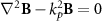 , where
  . In the cylindrical coordinates,
  meets
meets 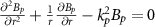 . Therefore, one has
 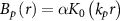 , where
  is a constant, and
  is the zeroth-order modified Bessel function. At the interface
  ,
,  , thus
 ![$\alpha = - 2\pi e{n_{b0}}\sigma _ \bot ^2r_0^{ - 1}\left[ {1 - \exp \left( { - \frac{{r_0^2}}{{\sigma _ \bot ^2}}} \right)} \right]/{K_0}\left( {{k_p}{r_0}} \right)$](https://content.cld.iop.org/journals/1367-2630/25/9/093016/revision2/njpacf153ieqn64.gif) , where
, where  is the beam self-magnetic field, and
  is the initial density. In consequence, the magnetic force term can exceed the electric term of the Lorentz force near the inner cone surface, producing a net focusing force on the beam. In the central region of the hollow cone, the electric repulsive force of the beam is almost completely compensated by its magnetic field pinching. Hence, the beam can be confined and focused magnetically within the cone. As a whole, the beam undergoes a large pinching force
  (figure 2(e)) as it travels through the cone with a decreasing diameter, where
 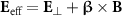 is the effective transverse field. Figure 2(f) shows the distribution of the self-generated magnetic fields, which agrees with our simulations. The electron beam energy spectrum is broadened a bit due to photon emission during the beam pinching, as presented in figure 2(g). However, since the unique interaction configuration where the electron beam is mainly located near the central axis and the effective field exists mainly on the inner surface of the cone wall, the beam energy loss during focusing can be limited to a few precent while its total charge is almost unchanged.
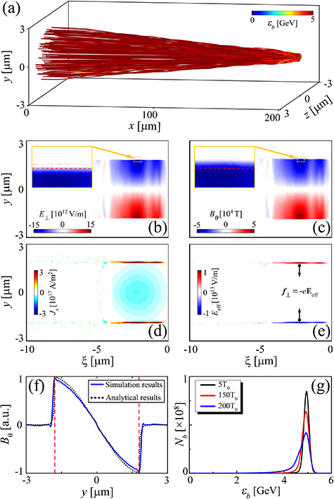
Figure 2. Three-dimensional particle-in-cell simulation results. (a) Trajectories of selected beam electrons. Distributions of (b) the transverse electric field ( ), (c) the azimuthal magnetic field (
 ), (d) the longitudinal electric current density (
 ) and (e) the effective transverse field (
 ) in the (
 ) plane, where
  , and
, and  . The insets in (b) and (c) display the corresponding fields within the yellow areas, where the red dashed lines represent the initial positions of the cone inner walls. The black arrows in (e) represent the directions of the Lorentz forces exerting on the beam. (f) Distribution of the self-generated magnetic fields along the y-axis, where the black dot curve shows the analytical results and the blue solid curve shows the simulation results. (g) Energy spectrum of the electron beam at stated times.
Download figure:
Standard image High-resolution imageAs the electron beam shrinks, its number density increases and its transverse radius decreases, which are two important characteristics of beam pinching. To clarify these two features, we investigate the maximum number density and the minimum radius of the focused electron beam. It is shown that an appropriately small cone angle is essential for beam pinching (figure 3(a)), which agrees with our analytical model (see methods). For example, when the cone open angle is reduced to about 0.5°, the minimum radius can be less than  , and the maximum density can reach
  , which is more than 100 times the initial peak density. Furthermore, they also depend on the aperture size of the cone tip, as discussed below.

Figure 3. Evolution of the focused beam density and radius. Effects of (a) the cone open angle ( ) and (b) its tip aperture diameter (
 ) on the maximum density (
 ) and the minimum radius (
 ) of the focused electron beam.
Download figure:
Standard image High-resolution imageOn the other hand, the outlet aperture size of the cone target also plays an important role in the focusing of the electron beam. It is shown that when the cone target has an appropriately small open angle (e.g., less than 0.9°), a relatively small outlet aperture is of great benefit to electron beam focusing. As the aperture diameter of the cone tip decreases, the electron beam can be focused along the cone to a smaller size, leading to a higher number density (figure 3(b)). Theoretically, the electron beam may be focused down to a spot size of order  . However, when the number density of the focused electron beam increases close to the target density, it is dense enough to expel the plasma electrons from the target surface, such that the beam self-fields cannot be fully shielded at the target surface, and the magnetic pinch effect is reduced. As a result, the focusing of the electron beam will reach a limit, yielding a spot size of about 0.1 μm. Additionally, if the cone tip aperture is reduced to zero (i.e. a closed cone), the electron beam will directly interact with the cone wall, which may cause substantial energy loss and hinder the beam pinching.
After interaction with the cone target, the beam diameter is reduced by about an order of magnitude and correspondingly its peak density is enhanced by two orders of magnitude from 1027 m−3 to over 1029 m−3, as presented in figure 4. In this stage, the beam mostly resides in the central region of the hollow cone that is the lowest field strength region (figures 4(d) and (e)), such that the electrons undergo moderate photon emission and retain more than 90% of the beam energy. This is very important for the next stage to trigger high-field QED effects, as well as other applications as mentioned earlier.
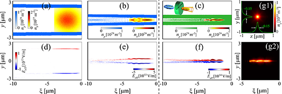
Figure 4. Beam focusing and photon emission. Beam focusing inside the cone in stage I and conversion to γ-rays in a thin-solid target in stage II. (a) and (b) Distributions of the beam density ( ) and plasma density (
 ) while the beam is located at the beginning and end of the cone in stage I, respectively, and (c) beam density and plasma density while the beam is passing through the converter in stage II. Figures (d), (e), and (f) show the effective transverse field (
 ) corresponding to (a), (b), and (c), respectively. (g1) and (g2) The transverse and longitudinal distributions of the emitted γ-ray beam.
Download figure:
Standard image High-resolution image2.4. Efficient generation of extremely bright γ-rays
Now we consider an example of applications with such dense electron beams to generate collimated bright γ-rays via beam–solid interaction by placing a thin solid foil with a thickness of  and the same density as the cone behind the cone tip as a γ-ray converter. The tightly-focused beam is dense enough (
 ) to expel nearly all plasma electrons from the beam volume, leaving the massive ions there. Because of their low velocities, the plasma electrons mainly experience the Coulomb repulsive force from the beam electrons. An almost electron-evacuated channel is formed as a result of the balance between the repulsive force of the beam electrons and the space charge force of the plasma ions. The static fields generated in the plasma channel are dramatically raised to above 1014V m−1 (figure 4(f)), where the electron beam is surrounded by the huge fields and undergoes stronger effective fields as it traverses the converter compared to in the hollow cone. This brings the quantum parameter up to
  , leading to a significant enhancement of high-energy photon emission. Finally, a highly-collimated γ-ray beam is produced with small size of ∼0.15 μm full width at half maximum and ultrahigh photon density on the order of 1030 m−3 (figure 4(g)). This results in unprecedented high brilliance of γ-rays, exceeding
  photons s−1 mm−2 mrad−2 per 0.1% bandwidth, as detailed in appendix
3. Discussion and conclusion
We now discuss the importance of beam-driven QED, which can be characterized by 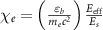 , where
  is the QED critical field. When
  approaches 1, it means entering the QED dominant regime. In our scenario, the effective field is dominated by the induced magnetic field, and the maximum field strength can be approximated as
  , where
  is the beam current and
  is the focused radius. Then, one can obtain
 ![${E_{{\text{eff}}}}\left[ {{\text{V}}\;{{\text{m}}^{ - 1}}} \right] \approx 6 \times {10^7}{I_b}\left[ {\text{A}} \right]/{r_b}\left[ {\mu {\text{m}}} \right]$](https://content.cld.iop.org/journals/1367-2630/25/9/093016/revision2/njpacf153ieqn89.gif) . For a beam with a duration of about 10 fs, we can derive
. For a beam with a duration of about 10 fs, we can derive ![${E_{{\text{eff}}}}\left[ {{\text{V}}\;{{\text{m}}^{ - 1}}} \right] \approx 6 \times {10^{12}}{Q_b}\left[ {{\text{nC}}} \right]/{r_b}\left[ {\mu {\text{m}}} \right]$](https://content.cld.iop.org/journals/1367-2630/25/9/093016/revision2/njpacf153ieqn90.gif) . Therefore, the QED parameter can be rewritten as
. Therefore, the QED parameter can be rewritten as

When the beam has a larger charge, it may create higher  and hence induce stronger QED effects, resulting in more effective photon emission with high efficiency up to 67%, as shown in figure 5. We can infer that for 5 GeV electrons, one needs
  in order to attain
  , assuming a minimum radius of approximately 0.1 μm. It is expected that if the beam has tens of nC charges and/or tens of GeV energies, it could usher in extreme QED regime, far beyond the scope of currently achievable experimental capabilities.
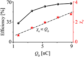
Figure 5. Beam-driven strong-field QED. The radiation efficiency and the maximum  as a function of the initial beam charge (
 ).
).
Download figure:
Standard image High-resolution imageIn conclusion, an effective approach is introduced to achieve self-pinching of relativistic high-flux electron beam in a hollow cone without additional magnetic devices, so that the beam can be focused by more than an order of magnitude to a submicron diameter and its density is increased by hundreds of times. Such ultradense beam can trigger strong-field QED effects in the absence of laser fields, for instance, by injecting it into solid targets to induce intense emission of high-energy photons. It is found that more than 60% of the beam energy can be transferred to copious collimated γ-rays, making it possible to develop compact ultrashort γ-ray sources in the GeV regime with unprecedented brilliance comparable to that of free-electron lasers. The scheme can also be used to focus other charged particles (e.g. positrons) for a wide variety of applications. This will open new avenues for research and applications in accelerator physics, beam–plasma physics and high-field physics, especially for high-luminosity colliders and compact bright light sources. In addition to these, it allows one to investigate some unexplored regimes with high-density electron beams such as radiative spin effects [65, 66].
4. Methods
4.1. Physical model of the beam focusing
In the following, we give a simple estimation on the cone open angle required for effective beam pinching. The trajectory of the electron beam at its edge in the self-generated magnetic fields can be described as

where  is the maximum field strength at the beam edge. For simplicity, the beam's current is assumed to be
  . Equation (2) can be integrated once to

where  is a constant,
  , and
, and  is a reduction factor due to the decrease in the pinching force. At the entrance of the cone, one has
  and
and  , thus
  . Substituting
  into equation (3), one obtains
  , which can be rewritten as
 ![$\frac{{dr}}{{dx}} = - {\left[ {f\sigma _ \bot ^2\frac{{\omega _{b0}^2}}{{2{c^2}{\gamma _b}}}\left( {\ln \frac{{{D_0}}}{{2r}}} \right)} \right]^{1/2}} =$](https://content.cld.iop.org/journals/1367-2630/25/9/093016/revision2/njpacf153ieqn106.gif)
![$- {\left[ {2f\frac{{\left| {{I_b}} \right|}}{{{I_A}}}\left( {\ln \frac{{{D_0}}}{{2r}}} \right)} \right]^{1/2}}$](https://content.cld.iop.org/journals/1367-2630/25/9/093016/revision2/njpacf153ieqn107.gif) using
using  , where
  , and
, and  is the Alfvén current. Assuming the final diameter of the focused beam is
  and let
which represents the beam focusing angle. In order to focus the electron beam effectively, the cone angle should satisfy the relation  . If taking
  ,
,  ,
,  ,
,  and
and  in one of our simulations, for instance, one has
  . This is consistent with our numerical observations in figure 3(a). From equation (4), one notes that
  depends strongly on the beam current
  , but relatively weakly depends upon the beam diameter ratio
  . We wish to emphasize that the beam focusing scheme can also be applied to focus other charged particles, e.g., positrons, as illustrated in appendix
In passing, we wish to point out that the instabilities normally found in long-time beam–plasma interactions such as the two-stream instablity, Weibel instability, and hosing instability do not develop significantly in our case. This is mainly due to ultrashort beam length of a few microns and that the beam propagates mainly inside the hollow cone target with a 100 μm-scale length. Therefore, these instabilities have weak effects on the propagation and focusing of the beam during the interaction.
4.2. The characteristics of strong-field QED
When a high-energy electron traverses intense electromagnetic fields, the rate of high-energy photon emission by the electron with energy  is given by [67]
 , where
  is the fine structure constant, and
  is the quantum-corrected synchrotron function. In the ultrarelativistic limit, the quantum parameter associated with strong-field QED can be characterized by

where  is the effective transverse field experienced by the electron, and
  is the electric field term perpendicular to the electron motion. The radiation power emitted by the electron can be written as

where ![${\text{g}}\left( {{\chi _e}} \right) \approx {\left[ {1 + 4.8\left( {1 + {\chi _e}} \right)\ln \left( {1 + 1.7{\chi _e}} \right) + 2.44\chi _e^2} \right]^{ - \frac{2}{3}}} \in \left( {0,\,1} \right)$](https://content.cld.iop.org/journals/1367-2630/25/9/093016/revision2/njpacf153ieqn129.gif) is the quantum-corrected function [67]. By substituting equation (5) into equation (6), the radiation power can be estimated by
is the quantum-corrected function [67]. By substituting equation (5) into equation (6), the radiation power can be estimated by  . Therefore, both QED effects and high-energy photon emission are mainly determined by the electron energy
  and the effective field
  . When the electron energy
  is fixed, the key to increase the radiation emission is to have extremely high
  . Many previous studies have proposed to achieve this by use of high-power intense lasers focused on the order of 1023W cm−2, allowing the paremater
  to be increased to 1 via the head-on collisions of focused laser fields with multi-GeV electrons or much higher intensity laser–plasma interactions. Technically achieving such extreme laser fields and stable laser-electron-beam head-on collisions are still challenging. Moreover, there are inevitable physical restrictions due to laser ponderomotive scattering and nonlinear effects, which cause large divergence and transverse size. These make it challenging to produce collimated high-brilliance γ-ray sources via electron beam collision with ultra-intense lasers. In this work, it is shown that such high effective fields can be realized via direct electron beam-target interactions without laser pulses, as described above in section 2.
Acknowledgments
This work was supported by the National Natural Science Foundation of China (Grant Nos. 12205186, 12135009, 11991074, and 11975154), the National Postdoctoral Program for Innovative Talents of China (BX20220206) and the Strategic Priority Research Program of Chinese Academy of Sciences (XDA25050100). The simulations were performed on the PI2 supercomputer at Shanghai Jiao Tong University.
Data availability statement
All data that support the findings of this study are included within the article (and any supplementary files).
Appendix A: Parameters of emitted gamma-rays
The advantage of our scheme is that both stages for the beam pinching and photon emission are quite efficient, as shown in figure 6. The first stage is primarily responsible for focusing the beam, while preserving about 92% of the beam energy, since the beam mostly occupies the lowest field region. As the pinched beam enters the second stage, it drives a plasma channel and induces stronger static fields, where the whole beam resides in the high-field region. Thus, high-energy photon emission can be substantially enhanced. About 54% of the beam energy can be transferred to γ-rays, with high photon energies up to 5 GeV and low divergence  mrad, as shown in figures 6(b) and (c). Note that because of QED correction, there is an upper bound on the energy of radiated photons, which cannot exceed the emitting electron energy. Taking these parameters together with a 8 fs-long duration and a 0.15 μm-wide size, the γ-ray pulse is found to reach a peak brilliance about
  photons s−1 mm−2 mrad−2 per 0.1% bandwidth at 1 MeV. Interestingly, even for higher energy γ-rays of up to 1 GeV with
  photons within the 0.1% energy bandwidth, their brilliance remains in the range of
  photons s−1 mm−2 mrad−2 per 0.1% bandwidth. To the best of our knowledge, this is the highest brilliance reported so far for γ-rays, several orders of magnitude higher than existing sources. Such energetic γ-rays are inaccessible to conventional radiation sources such as synchrotrons and x-ray free-electron lasers.
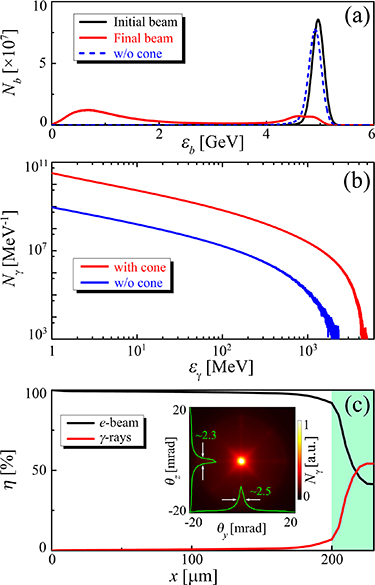
Figure 6. Generation of bright gamma-rays. (a) The initial and final energy distribution of the electron beam, where the blue dashed line represents the final energy spectrum without the cone. (b) Final energy spectra of γ-rays with (red line) and without (blue line) the cone. (c) Evolution of the energy efficiency of the electron beam and γ-rays, where the green shaded area indicates the radiation stage in the converter, and the inset displays the angular distribution of γ-ray source.
Download figure:
Standard image High-resolution imageFor comparison, we also investigate the case without a cone target, where the converter target has a  diameter and other parameters are the same as those in the cone case. Due to the lack of the pinching effect, the driving beam density (
 ) is too low to excite an electron-depleted plasma channel (requiring
  ). There is no obvious beam focusing and no channel field excitation, leading to inefficient γ-ray radiation with very low energy and photon number (see figure 6(b)). As a result, less than 1% of the electron beam energy can be converted into γ-rays. Furthermore, the γ-ray source has a large size comparable to that of the initial electron beam. These result in the γ-ray brilliance roughly four orders of magnitude lower than in the cone case.
Appendix B: The focusing of relativistic positron beams
In addition to electron beams, the proposed scheme is also applicable to focusing other charged particle beams. Here we use a relativistic beam of positively charged particles (e.g. positrons) as an example to demonstrate this. It can be seen that the positron beam can be well focused in our configuration, as shown in figure 7. Compared with electron beam focusing, the focusing of positron beam is relatively weak, with the maximum density reduced by about half and the minimum radius increased by about 1.5 times. This is because the target electrons will be attracted by the positron beam towards the cone axis at the late stage of beam focusing. This leads to a weakening of the induced magnetic field, which can be roughly described as 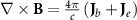 , where
  is the beam current density and
  is the current density of attracted target electrons. Since less radiation is produced in the relatively low field, the positron beam retains more energy during the focusing, i.e. about 99% of the initial beam energy is left after passing through the cone target.

Figure 7. Focusing of relativistic positron beam. (a) Trajectories of selected positrons. The inset displays the initial (black line) and final (red line) energy spectra of positrons. Distributions of (b), (c) the positron beam density ( ) and (d), (e) the effective transverse field (
 ) are shown at the beginning (b), (d) and the end (c), (e) of the cone target.
Download figure:
Standard image High-resolution image