


Abstract
We theoretically propose and experimentally demonstrate a flexible approach to generate an arbitrary shape-invariant structured array beam during propagation with the prescribed intensity distribution. An algorithm for generating flexible desired phase is presented according the reverse engineering and Huygens–Fresnel theory. In this paper, we outline the theory for creating the shape-invariant array beams. The numerical simulation results show that the shape of generated array beams is invariant and its size increases gradually from the near field to the far field. The generation of shape-invariant structured array beams can be realized by the phase-only and amplitude-only elements encoded on the spatial light modulators. The generated arbitrary shape-invariant structured array beams are verified and are in excellent agreement with the theory.
Export citation and abstract BibTeX RIS

Original content from this work may be used under the terms of the Creative Commons Attribution 4.0 license. Any further distribution of this work must maintain attribution to the author(s) and the title of the work, journal citation and DOI.
1. Introduction
During the last decades, the structured light beams have attracted a rapid growth of attention due to their unique characteristics of intensity, phase and polarization [1–3]. These include, for instance, vortex beams carrying helical wave front have the hollow intensity distribution and a phase singularity [4], cylindrical vector beams with polarization singularities have cylindrical symmetry polarization distributions in space domain [5], and the realization of cylindrical vector vortex beams with both spatiotemporal optical vortex and spatial polarization singularity [6]. Nowadays, the flexible control of structured light in amplitude, phase and polarization can be achieved inside a laser cavity [7]. With the exploitation of the transverse modes, the structured light beams extend tremendous potential applications in optical communications, optical tweezers, optical encryption and laser-based material processing [8–11].
Driven by the numerous novel applications, the approaches to generate structured light beams include directly generation and external beam shaping has been proposed [1]. Although the methods of direct generation can achieve a relatively high efficiency and high mode purity, the variety of output modes generated by these methods is limited. By comparison, the methods by employing external beam-shaping optics, including spatial light modulators (SLMs) [12]. Long-period fiber grating [13], q-plate [14], spin–orbit approaches [15], digital mirror device [16], spiral phase plate [17] and all-fiber cylindrical vector beams laser based on the principle of mode superposition [18], offer a great deal of flexibility. Among these, the SLMs could provide flexible modulation to generate arbitrary structured light, because the SLMs allow active control of the phase and amplitude [19]. Up to now, the generation of various structured beams by using the SLMs, including vector beams [20], vectorial vortex beams [21], Bessel beams [12], Laguerre–Gaussian beams [22] and a light beam with high self-reconstruction ability of the degree of coherence [23] has been proposed theoretically and verified experimentally.
On the other hand, diffraction is an important natural feature of light. It is difficult for the array beams to preserve its shape during propagation in free space due to the effect of the interference between the single beams, but a single structured beams only increase in size while keeping the shape. That is to say, it is hard to apply the structured beam arrays in these potential applications, including free-space optical communications [24] and long-distance power transmission [25]. It was not until the discovery of Bessel beam that the diffraction effect was resisted [26]. As is well known, Bessel beam is one of the most important nondiffracting beam. Since then, Airy beams [27], optical needle [28] and pin-like optical vortex beams [29] are discovered as the typical nondiffracting beams with propagation-invariant properties. Although these particular non-diffracting beams can suppress the diffraction effect, the non-diffracting distance is restricted to the wavelength level [30]. Moreover, the types of non-diffracting beams are limited. In particular, the shape-invariant Bessel-like beams and flat-top beams are generated experimentally [31, 32]. In order to maintain the beam shape of structured beam during propagation, the salient challenge is the lack of the theoretical basis for designing the propagation-invariant structured array beams. Based on the theory of reverse engineering [33, 34], we propose an approach to generate arbitrary propagation-invariant structured light beams, and demonstrate the feasibility of the theory experimentally.
In this paper, we present a new approach permitting one to generate arbitrary structured array beams with shape-invariant characteristics, which can be done by simply attaching a designed far-field phase to the initial field. Theoretical and experimental verifications have been done for the generation of arbitrary shape-invariant structured array beams. The results may be helpful for further potential applications of structured array beams.
2. Theoretical analysis
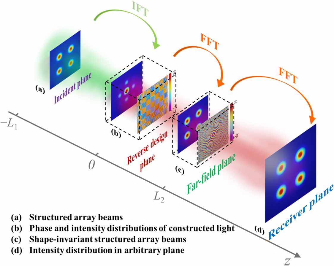
In what follows, we outline the theory for creating the shape-invariant array beams. In [34], we proposed the greedy algorithms to generate the array beams at different distances. However, the initial phase should be redesigned for different distances. In this paper, we optimized the method to achieve the shape-invariant properties by phase modulation. The schematic configuration of the generation principle of arbitrary shape-invariant structured array beams is shown in figure 1. The significant point to generate shape-invariant structured array beams is to acquire the corresponding far-filed phase [35, 36], that means, a beam with a far-field phase can keep its intensity distribution invariant during propagation. Thus, our purpose is to calculate the corresponding phase distributions of structured beam arrays according to back-propagating of the desired structured array beam. The steps are shown as follows. Firstly, by means of the reverse engineering approach, the phase and intensity distributions of constructed array beam in the reverse design plane are obtained through the back-propagation according to the structured array beam in the incident plane (see figures 1(a) and (b)). And then, the intensity and designed far-field phase distributions of structured array beam in the far-field plane can be obtained as the constructed light propagates to the far-field (see figures 1(b) and (c)). It is noted that the phase distribution in the far-field plane is the key to generate shape-invariant structured array beams. By this way, the far-field phase of arbitrary structured array beam can be achieved. Once the far-field phase is added on the structured array beam, it will propagate with shape-invariant characteristics.

Figure 1. Schematic configuration of the generation principle of arbitrary shape-invariant structured array beams.
Download figure:
Standard image High-resolution imageNow, we will introduce the design principles. The first step is to yield the constructed light through back-propagating the structured array beams to the incident plane. Based on the reverse propagation of the diffraction theory, the optical field in the reverse design plane can be expressed as

where U0 and UL
1 are the constructed optical field and desired structured optical field, respectively. (x1, y1) and (ξ1, η1) are the coordinates in the reverse design plane and incident plane, respectively.  is the wave number related to the wavelength λ. L1 is the back-propagation distance.
  denotes the inverse Fourier transform (IFT).
The propagation of the constructed light can be calculated by the Huygens–Fresnel diffraction integral and can be implemented by the following FT

where UL
2 is the designed structured array beams.  represents the far field plane. (x2, y2) are the coordinates in the far-field plane. L2 is the propagation distance.
  denotes the FT.
The optical field and phase distributions in the far field can be obtained by substituting equation (1) into equation (2). The designed far-field phase of structured light is ![$\varphi = \arg \left[ {{U_{L{\text{2}}}}\left( {{x_2},{y_2},z = {L_2}} \right)} \right]$](https://content.cld.iop.org/journals/1367-2630/25/5/053029/revision2/njpacd6b1ieqn5.gif) . The active algorithm can provide an effective way to generate the desired far-field phase for different structured light. The optical field of shape-invariant structured light can be expressed as
. The active algorithm can provide an effective way to generate the desired far-field phase for different structured light. The optical field of shape-invariant structured light can be expressed as

The designed far-field phase can be generated by the hologram  displayed on the phase-only SLM (P-SLM). The output beam after the P-SLM is
 ![${U_{{\text{output}}}} = {U_{{\text{in}}}}\exp \left[ {{\text{i}}H\left( {x,y} \right)} \right]$](https://content.cld.iop.org/journals/1367-2630/25/5/053029/revision2/njpacd6b1ieqn7.gif) .
.
As the theoretical analysis mentioned above, the significant point to obtain the shape-invariant structured array beams is the design of far-field phase. That means, the structured array beams can have the properties of shape-invariant during propagation by adding the designed far-field phases. Now, we numerically analyze the propagation properties of shape-invariant structured light by using numerical examples. The structured array beams we choose are Gaussian array beam and vortex array beam composed of four beamlets in a tiled quadrilateral architecture.
Consider that an array beam is composed of Nth individual beams. The total optical field of Gaussian array beam can be expressed as

where (aj, bj
) are the center coordinates of the jth beamlet. w0 is the beam radius of Gaussian beam. The far-field phase can be obtained by substituting the total optical field into equations (1) and (2). The simulation parameters of Gaussian array beam are as follows: w0 = 0.1 mm, λ= 638 nm, N = 4, L1 = 1 m, L2 = 9 km,  .
.
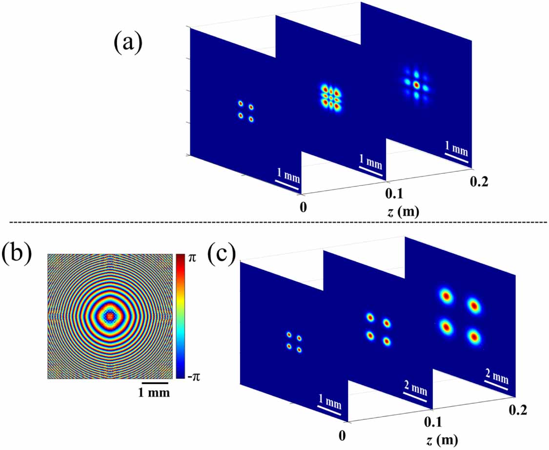
The intensity distributions of Gaussian array beams versus propagation distances are illustrated in figure 2. Figure 2(a) shows the typical evolution of intensity distributions of Gaussian array beams without designed far-field phase at several distances. It can be seen that the intensity distribution is changed due to the effect of the interference between the single beams with the increasing propagation distance. The phase distribution in figure 2(b) is the designed far-field phase of Gaussian array beam calculated by the active algorithm. However, as the designed far-field phase is placed in front of the Gaussian array beam, the evolution property of Gaussian array beam is changed (as shown in figure 2(c)). One can see that the shape of the Gaussian array beam keeps unchanged during propagation compared with figure 2(a). That is to say, the generation of shape-invariant Gaussian array beam is realized successfully by adding a designed far-field phase.
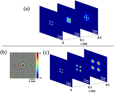
Figure 2. Intensity distributions of Gaussian array beams versus propagation distances without and with designed far-field phase, respectively.
Download figure:
Standard image High-resolution imageFurther, the generation of shape-invariant vortex array beam is investigated. In the same way, the total optical field of vortex array beam can be written as

where sgn(•) is sign function, l is the topological charge. The simulation parameters of vortex array beam are as follows: w0 = 0.1 mm, λ= 638 nm, l = 6, N = 4, L1 = 10 m, L2 = 5 km,  .
.
The intensity distributions of vortex array beam versus propagation distances are illustrated in figure 3. From figure 3(a) we can see that the beam shape of vortex array beam becomes a circular distribution of small spots in the far-field. As a result, the application of vortex array beam will be limit due to the effect of the interference between the single beams. To generate the shape-invariant vortex array beam, the designed far-field phase is calculated as shown in figure 3(b). Figure 3(c) presents the intensity distributions of vortex array beam at different distances after adding the designed far-field phase. As can be seen, the vortex array beam propagates with unchanged shape by phase modulation. Similarly, arbitrary shape-invariant structured light can be generated according to the above designed principles.
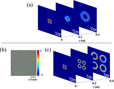
Figure 3. Intensity distributions of vortex array beams versus propagation distances without and with designed far-field phase, respectively.
Download figure:
Standard image High-resolution image3. Experimental results
We now implement an experimental setup to verify the feasibility of the generation principles of the arbitrary shape-invariant structured array beams. The experimental step is depicted in figure 4. A collimated linearly polarization laser beam output from the solid laser (λ = 638 nm) passes through the polarizers and then incident on the surface of the amplitude-only SLM (A-SLM). The purpose of the A-SLM is to generate special intensity distributed laser beam by modulating the amplitude. The reflected light from A-SLM passes through the polarizers and then the designed far-field phase is loaded into the modulated beam by the P-SLM. It is noted that the backlighting generated from A-SLM will influence the intensity distribution in the receiver plane. A circle aperture is employed to remove unwanted backlighting. Due to the limited acquisition range of the charge-coupled diode (CCD) camera, the structured beam is focused by a lens. The desired shape-invariant structured array is incident on the focusing lens (f = 20 cm), and the focal light is captured by a CCD camera.
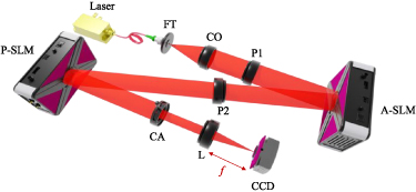
Figure 4. Experimental setup to generate arbitrary shape-invariant structured array. FT: fiber tip; CO: collimator; P1, P2: polarizers; A-SLM: amplitude-only spatial light modulator; P-SLM: phase-only spatial light modulator; CA: circle aperture; L: lens; CCD: charge-coupled device.
Download figure:
Standard image High-resolution imageTo avoid the strong zeroth order light (undiffracted light) caused by the first surface reflection of P-SLM, the blazed grating is added to the calculated hologram. The blazed grating can move the structure light (first order light) away from the zeroth order light at an angle. The distance is determined by the spatial frequency of the blazed grating, i.e. the higher the spatial frequency, the farther from axis the structured beam is moved. Thus, the final holograms encoded on the P-SLM include a linear phase ramp produced by the blazed grating. The holograms encoded the modulation phase are shown in figure 5. Figures 5(a) and (b) are the designed far-field phases encoded on the P-SLM to generate shape-invariant Gaussian array beam and vortex array beam, respectively.
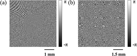
Figure 5. Holograms encoded on the SLM with a blazed grating.
Download figure:
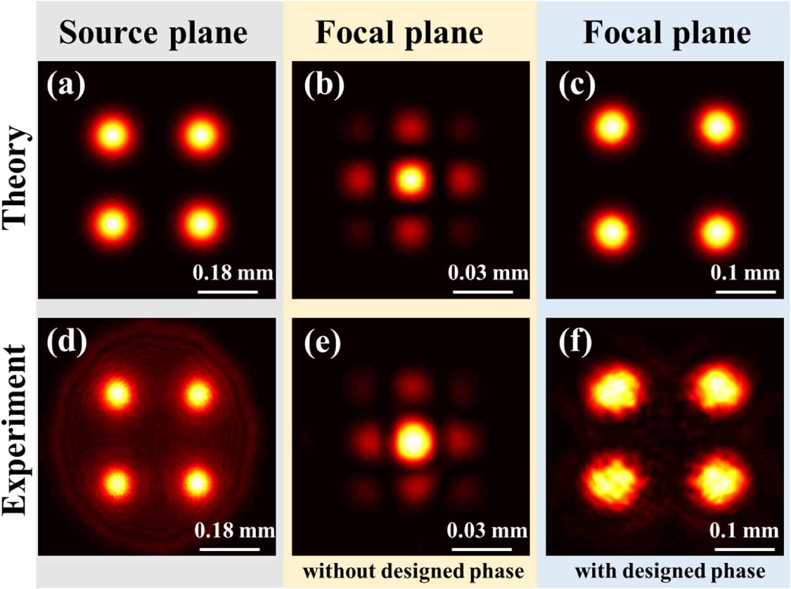
Standard image High-resolution imageThe comparison between the theoretical results and experimental results of the shape-invariant Gaussian array beam is shown in figure 6. The first column of figure 6 shows the theoretical results of the shape-invariant Gaussian array beams at different planes. The second column shows the experimental intensity profiles of Gaussian array beams. From figures 6(a) and (b), it can be seen that the intensity profile in the focal plane is the result of the coherent superposition of four linearly polarized Gaussian beams. After encode the hologram of designed far-field phase (as shown in figure 5(a)) on the Gaussian array beam, the desired intensity profile in the focal plane is identical to that in the source plane. By comparing figures 6(a)–(c) and (d)–(f), it can be seen that the intensity profiles of experimental results agree well with that of the corresponding theoretical results. In other words, the shape-invariant Gaussian array beam is generated successfully by adding the appropriate designed far-field phase. It should be noted that the Gaussian array beam in source plane is captured by a CCD camera without being focused. Thus, the concentric rings caused by the circle aperture is obvious as shown in figure 6(d). The similarity between experimental results and simulation results can be determined by the correlation, which is defined as [37]
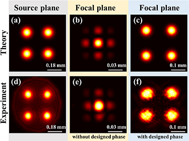
Figure 6. Theoretical (top row) and experimental (bottom row) intensity profiles of Gaussian array beams at different planes: (a) and (d) source plane, (b) and (e) focal plane without designed phase, (c) and (f) focal plane with designed far-field phase.
Download figure:
Standard image High-resolution imagewhere  and
and  is the corresponding mean value of theoretical beam intensity It
or experimental beam intensity Ie
. The value of correlation C is 0–1. The larger value of C means the more similarity between experimental results and simulation results. The values of correlation C at source plane and focal plane with designed phase are 0.9217 and 0.9167, respectively. That means, the method proposed in this paper is effective for generating the shape-invariant Gaussian array beams.
is the corresponding mean value of theoretical beam intensity It
or experimental beam intensity Ie
. The value of correlation C is 0–1. The larger value of C means the more similarity between experimental results and simulation results. The values of correlation C at source plane and focal plane with designed phase are 0.9217 and 0.9167, respectively. That means, the method proposed in this paper is effective for generating the shape-invariant Gaussian array beams.
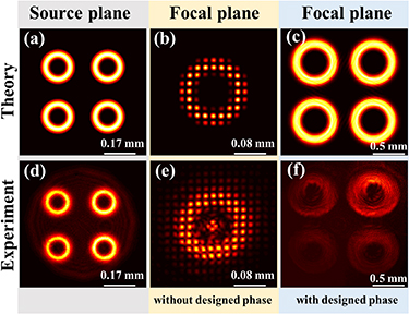
We next examine the generation of the shape-invariant vortex array beam by adjusting the corresponding designed far-field phase in the source plane. In this case, the topological charge l = 6. The theoretical and experimental intensity profiles of vortex array beams at different planes are shown in figure 7. As can be seen in figure 7(b) that the intensity profile of vortex array beam in the focal plane is composed by a circular distribution of small spots. After encode the hologram of designed far-field phase (as shown in figure 5(b)) on the vortex array beam, it is clearly seen that the intensity profile of the vortex array remains unchanged (as shown in figure 7(c)). The experimental results are shown in figures 7(d)–(f), which is in good agreement with the corresponding numerical results in the focal plane. The values of correlation C at source plane and focal plane with designed phase are 0.829 and 0.5715, respectively. The lower value in the focal plane is caused by the uneven intensity distribution. It should be noted that, in order to avoid the influence of strong zeroth order light, the vortex array beam should be far enough away from the central position. Thus, compared with Gaussian array beam, the spatial frequency of blazed grating of vortex array beam is higher. As a result, the intensity of shape-invariant vortex array beam measured on the focal plane is weak. For the above reasons, from figure 7(f) it can be seen that the intensity near the central axis (i.e. upper right) is stronger than that away from the central center (i.e. lower left). On the other hand, the focal size of the vortex array beam is much bigger than that of the Gaussian array beam. This is also the reason for the weakening of the light intensity of vortex array beam. In order to present a better result, the vortex array beam in the source plane is not added with blazed grating, resulting in the zeroth order light focused on the center as shown in figure 7(e).
Figure 7. Theoretical (top row) and experimental (bottom row) intensity profiles of vortex array beams at different planes: (a) and (d) source plane, (b) and (e) focal plane without designed phase, (c) and (f) focal plane with designed far-field phase.
Download figure:
Standard image High-resolution image
4. Conclusion
In this paper, we propose and demonstrate a new method to generate arbitrary shape-invariant structured array beams. According to the reverse engineering and Huygens–Fresnel theory, we present a flexible approach to generate far-field phase of arbitrary structured array. We present two examples to verify the feasibility of the design principles. The shape-invariant Gaussian array beam and vortex array beam are generated theoretically and experimentally. It is shown that the shape-invariant structured array beams can keep the shape invariant during propagation by adding a designed far-field phase. By comparing the intensity distributions with and without the designed far-field phase, it is shown that the designed phase is beneficial to maintain the beam shape over long distances. Moreover, we carry out experiments to demonstrate the feasibility of our theory. It is demonstrated that using the phase holograms encoded on the SLM, the shape-invariant structured array beams can be realized experimentally. The experimental results are in excellent agreement with theory. The method is suitable for coherent beam combination systems to generate structured array beams with shape-invariant properties. This work may have a considerable impaction for the applications of structured array beams in optical communications and long-distance power transmission.
Acknowledgments
This work was supported in part by Innovative Research Groups of Hunan Province (Grant No. 2019JJ10005), in part by Hunan Provincial Innovation Construct Project (Grant No. 2019RS3017).
Data availability statement
All data that support the findings of this study are included within the article (and any supplementary files).