


Abstract
We present the experimental implementation of a two-qubit phase gate, using a radio frequency (RF) controlled trapped-ion quantum processor. The RF-driven gate is generated by a pulsed dynamical decoupling sequence applied to the ions' carrier transitions only. It allows for a tunable phase shift with high-fidelity results. The conditional phase shift is measured using a Ramsey-type measurement with an inferred fringe contrast of up to  . We also prepare a Bell state using this laser-free gate. The phase gate is robust against common sources of error. We investigate the effect of the excitation of the center-of-mass (COM) mode, errors in the axial trap frequency, pulse area errors and errors in sequence timing. The contrast of the phase gate is not significantly reduced up to a COM mode excitation
  20 phonons, trap frequency errors of +10%, and pulse area errors of −8%. The phase shift is not significantly affected up to
  10 phonons and pulse area errors of −2%. Both, contrast and phase shift are robust to timing errors up to −30% and +15%. The gate implementation is resource efficient, since only a single driving field is required per ion. Furthermore, it holds the potential for fast gate speeds (gate times on the order of 100 µs) by using two axial motional modes of a two-ion crystal through improved setups.
Export citation and abstract BibTeX RIS

Original content from this work may be used under the terms of the Creative Commons Attribution 4.0 license. Any further distribution of this work must maintain attribution to the author(s) and the title of the work, journal citation and DOI.
1. Introduction
Trapped atomic ions are one of the leading platforms for realizing quantum computers (QC). High-fidelity two-qubit entangling gates and Bell state preparation experiments have been realized in these systems using laser light to coherently drive qubit resonances and their motional sidebands (e.g. [1–7]). RF-controlled trapped ions promise quantum processors that are less challenging to scale up, since they do not rely on complex and demanding laser systems but use highly developed and easily accessible RF technology instead [8–15]. For individual ion addressing and multi-ion coupling, either RF fields and a static magnetic field gradient are utilized [8] or RF fields providing an oscillating magnetic gradient [9, 16, 17]. In this work the static gradient approach is used.
In RF-based trapped-ion QC, single-qubit rotations have been carried out with high fidelity [18, 19] and unrivaled low crosstalk [20], while two-qubit gate fidelities are on par with laser-based approaches. Recently, various approaches for robust two-qubit gates, as well as maximally entangled states with fidelities of up to 0.9977 have been reported in RF-based trapped ions [21–24], mostly relying on the application of several driving fields on or near the motional sidebands of each ion.
A versatile technique to protect quantum gates against decoherence is dynamical decoupling (DD), based on the application of additional continuous driving fields, sequences of RF pulses or a combination of both [11, 22, 25–30], generalizing earlier concepts for laser-driven trapped ions [31]. In this work, the gate is generated by the DD sequence by tuning its pulse timings to match the ion motion. Pulses are applied only to the carrier transitions of a two-ion crystal [32]. By tuning pulse timings to the period of the axial motional modes of the crystal, a tunable conditional phase shift is generated between the ions, while rendering the evolution robust to several major sources of gate errors.
The paper is structured as follows. First, the experimental setup is outlined, before the gate mechanism and its derivation are described. Then, measurement results are presented for the conditional phase shift and the preparation of a Bell state. Furthermore, the robustness of the gate to motional excitation, errors in axial trap frequency, pulse areas, and sequence timings are reported.
2. Experimental setup
The two-qubit system used in this work is provided by a set of two 171Yb+ ions trapped in a macroscopic linear Paul trap with radial and axial trapping frequencies of about  kHz and
  kHz respectively [15]. The ions are Doppler cooled by laser light near 369.5 nm, which is also used for state read-out and preparation. Additional laser light near 935 nm and 638 nm provides repumping from long-lived states back into the cooling cycle [33, 34]. Figure 1 depicts a partial energy level structure of 171Yb+. The ground state hyperfine levels used as qubit states are
  and
and  .
.

Figure 1. Partial energy level structure of  including the hyperfine and Zeeman sublevels of the atomic ground state. Qubits are formed by the
  and the
  ,
,  levels (marked in red) with an energy splitting corresponding to 12.6 GHz. Coherent operations are performed by RF radiation of the respective frequency. Incoherent driving for coolingand read-out uses laser light at 369.5 nm, driving the
  transition. Two additional optical transitions for repumping out of long-lived meta-stable states are not shown.
Download figure:
Standard image High-resolution imageAll coherent operations on the qubit states are carried out by applying global RF radiation near 12.6 GHz to the ion crystal. Two permanent magnets held by the endcap electrodes generate a magnetic field gradient of 19 T m−1 along the trap axis (z-axis), allowing for individual addressing of each ion in frequency space enabled by individual Zeeman shifts. In addition, coupling of the ion's internal and motional states is provided via magnetic gradient induced coupling (MAGIC) [8, 10, 13].
Here, single qubit operations are carried out with a Rabi frequency of  kHz, i.e. π-pulse times of
  s. The axial center-of-mass (COM) mode of the common motion of the ion crystal at frequency
  kHz is used for multi-qubit interaction.
Cooling beyond the Doppler limit is achieved by RF sideband cooling [35]. RF radiation drives a qubit's red sideband transition in addition to the laser at 369.5 nm, blue-detuned by 2.1 GHz using acousto-optical modulation. Ion motion within the harmonic trapping potential can be cooled down close to its ground state, with typically about 0.5 phonons. State preparation is performed by optical pumping using the  transition, which yields a well-defined initial state
  with a preparation efficiency
  [36].
[36].
Read-out of the qubit state is based on resonance fluorescence obtained by driving the  transition with laser light near 369.5 nm. The qubit state is projected to the
  ,
,  basis, which is distinguished by the amount of fluorescence photons gathered with an electron-multiplying charge-coupled device (EMCCD) camera. A double-threshold analysis is used to distinguish between the dark
  and bright
  states with fidelities of 99.5% and 98.5% respectively [37]. These values summarize state preparation and measurement (SPAM) errors, and all experimental results are corrected accordingly.
3. Gate mechanism
As detailed in [32], the quantum gate is designed based on the adaptive XY (AXY) sequence [38] that was initially developed for quantum control of electronic spins in solids. A similar construction has been used for quantum sensing purposes in Nitrogen vacancy centers [39, 40]. The AXY sequence is a series of DD pulses applied to the carrier transitions of a two-ion crystal. Tunable pulse timings allow for adaption to the motional mode frequencies of the ions, providing the necessary coupling between qubit states and motional states.
In the limit of very short pulses, the dynamical decoupling sequence is capable of resonantly exciting the ion motion by flipping the qubit state with the right timing with respect to the ions' vibrational motion. One should note that, in the presence of state-dependent potentials, flipping the qubit state implies that the ion is transferred between different potentials. For more than one qubit, this mechanism is able to generate qubit–qubit entanglement [32].
Two blocks consisting of five RF π-pulses each, serve as building blocks of the DD sequence. As sketched in figure 2, three tunable parameters  and τ encode the time distance between π-pulses and determine block timings. Phases of
  and
and  determine the rotation axes on the Bloch sphere and yield a self-correcting characteristic, i.e. robustness to pulse errors. Due to the
  phase difference, the two blocks are labeled X and Y.

Figure 2. Building blocks of the adaptive XY decoupling sequence. Each block consists of a series of five non-equidistant π pulses, distributed by the block duration τ and the pulse positions τa and τb . Numbers above the pulses indicate the respective phases within each block, which provide robustness to pulse errors.
Download figure:
Standard image High-resolution imageIf sequence timings are set such that the rates with which pulses are applied match the period of the motional modes of the ion crystal, a phase shift is generated between the ions. Namely the COM mode is selectively addressed via the block length τ, while the pulse positions, determined by τa
and τb
can be tuned to match with the breathing mode frequency. Using calculations and numerical simulations, the sequence is adjusted to decouple the electronic degrees of freedom from the motion at the gate time  , while a nonzero phase shift Φ is generated [32], resulting in the gate

In this notation a factor of  is absorbed into the gate, i.e. the observed phase shift is

Numerous combinations of  are possible, allowing for a tunable phase shift at the end of the gate. Here, we focus on the special case of a
  gate, which can be used for CNOT and entangling operations as shown in the following.
The possibility to match the gate parameters to both modes of the ion motion simultaneously allows for higher gate speeds than single-mode gates [29]. Spin-motion coupling is generated by the magnetic field gradient, which hence determines the speed of the gate. Since RF driving is applied to the ions' carrier transitions only, large couplings to both vibrational modes (COM and breathing mode) require large Rabi frequencies.
A DD sequence with a suitable number of pulses to protect the experimental system against decoherence is constructed by concatenating m of X and Y blocks (see [32] for details). In the experiments presented here, a total number of 80–160 pulses is used, which yields sequences of m = 16 or m = 32 blocks (AXY-16 and AXY-32 respectively). The corresponding gate times are given by  ms.
ms.
The gate is very resource efficient, as it can be implemented with a single driving field per ion and even a single global field is sufficient, if pulses are applied sequentially to both ions. For many qubits, signal generators reach their capacity limits, in terms of amplitude resolution, storage capacity, and amplifier power. Thus it is beneficial to minimize the number of RF fields for scaling up to larger systems. Here, we implemented the gate with one RF driving field per qubit.
Following the derivation in [32], the two-ion Hamiltonian

describes the system with qubit energies ωj
, motional mode eigenfrequencies νk
and the respective coupling constants  , using the Pauli matrix σz
and creation and annihilation operators a and
, using the Pauli matrix σz
and creation and annihilation operators a and  (here,
  is set to unity). RF driving of both of the atomic carrier transitions with Rabi frequencies
  and phases ϕj
is expressed as
and phases ϕj
is expressed as

using the Pauli matrix σx .
In a suitable rotating frame with respect to qubit energies, motional frequencies and RF drivings, the interaction Hamiltonian reads

taking the pulsed nature of the driving fields into account by the modulation functions  for an even or odd number of pulses respectively.
Solving the Schrödinger equation for this Hamiltonian, a propagator U is obtained with


Here, the term US
contains the coupling between internal and motional states with the functions  , while the final term UC
corresponds to the desired phase gate, with a phase shift
, while the final term UC
corresponds to the desired phase gate, with a phase shift  .
.
Simulations in [32] predict a gate with fidelities exceeding 99.9% for certain experimental parameters but neglecting decoherence sources. Here, in the case of small Rabi frequencies, still fidelities around 99% are predicted.
The AXY pulse sequence is tuned such that the block length τ is set with respect to the COM mode frequency ν1 and satisfies  , with an integer r, ensuring
  . Thus decoupling of the electronic degrees of freedom from the COM mode is achieved at integer multiples of τ, while a conditional, nonzero phase shift
  remains. Positions τa
and τb
of the pules within a block are then numerically optimized with respect to the breathing mode frequency ν2, to minimize
remains. Positions τa
and τb
of the pules within a block are then numerically optimized with respect to the breathing mode frequency ν2, to minimize  , thus decoupling the breathing mode. A set
  can be chosen, such that a desired phase shift
  is provided. Hence the phase shift is tunable by adjusting the sequence timings.
Our current setup does not allow to exploit the speed-up that would result from the simultaneous use of multiple modes, as we work in the Lamb–Dicke (LD) regime, i.e.  . Outside of the LD regime, [32] provides a method to achieve high-fidelity gates where the two modes of the ion chain contribute to the final gate phase, with gate times on the order of
  . We expect to exploit this feature in future setups with higher magnetic gradient and Rabi frequencies.
4. Measurements and results
The AXY sequence provides a conditional phase gate between a pair of qubits. We hence demonstrate the gate mechanism by Ramsey-type experiments, which allow to measure the phase shift  according to equation (2). In addition to the phase information, the Ramsey fringe contrast serves as a figure of merit for the ability of the sequence to overcome decoherence effects. An application of the phase gate is given by implementing an entangling operation, where generation of a Bell state is demonstrated. This measurement is composed from the AXY DD sequence and additional single qubit rotations. Furthermore, we investigate in detail the effect of various sources of error on the gate by measuring their influence on the resulting phase shift as well as on the Ramsey fringe contrast.
The measurement procedure is as follows. The ions are cooled close to the motional ground state, then initialized in the logical  state by optical pumping. This is followed by coherent manipulation using RF radiation, which implements the AXY DD sequence and additional single-qubit operations as given in the respective sections below. Finally, laser illumination is used for state read-out.
4.1. Phase shift
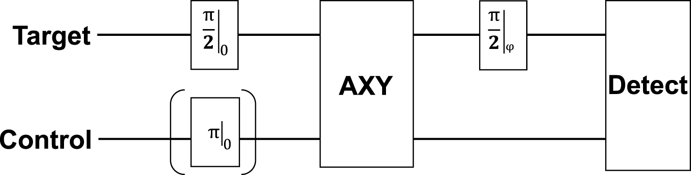
First, the phase shift  is assessed by Ramsey-type measurements. Figure 3 illustrates the RF sequence of two
  -pulses applied to the target qubit with a fixed phase of 0 for the first pulse and a variable phase ϕ for the second pulse. In between the pulses, the AXY decoupling sequence is applied to both qubits simultaneously with one RF field per ion. To measure the conditional response of the gate, the control qubit can alternatively be initialized in state
  by an additional RF π-pulse. After coherent RF manipulation, the laser at 369.5 nm is switched on to read-out the final state.

Figure 3. RF sequence applied to a two-ion crystal for measuring the phase shift of the AXY sequence. A Ramsey measurement is performed on the target qubit, in the form of two  -pulses, while the control qubit is initialized to
  or
or  by an optional π-pulse. In between the Ramsey pulses, the AXY gate sequence is applied to both qubits. State-selective detection by laser light reads out the final state of both qubits.
Download figure:
Standard image High-resolution imageThe pulse sequence shown in figure 3 is applied to a set of two qubits and the excitation probability of the target qubit is measured as a function of the phase of the second Ramsey pulse. Figure 4 shows the results obtained from using an AXY-16 sequence (80 DD pulses) designed for a  gate. Following equation (2), phase shifts
  and
and  are measured with control qubit preparations
  (red data points) and
  (blue data points), respectively, with fringe contrast of
  and
and  . Hence, a phase difference of π is obtained between the red and blue curves at the target qubit when the control qubit's state is changed. The gate time is 6 ms. Thus the phase shift matches the simulations, the conditional response of the sequence is confirmed and the fringe contrast allows for high-fidelity operations.

Figure 4. Ramsey measurement on the target qubit, when the AXY phase gate is applied to a two-ion system. The control qubit is initialized to  (red) or
  (blue) to verify the conditional response of the gate. The former case results in a phase shift of
  with fringe contrast of
  , the latter in a shift of
  and
and  . Hence the phase difference between the two curves is π. The dashed line marks the phase setting for the second
  pulse, for which a CNOT operation results. Accordingly a phase of
  results in
  for the red curve and
  for the blue curve.
Download figure:
Standard image High-resolution image4.2. Entanglement
Conditional phase gates are applicable for the generation of entanglement. For instance, a conditional  phase gate allows for a CNOT operation and hence preparation of maximally entangled Bell states. The dashed vertical line in figure 4 marks the phase setting for the second
  pulse, for which a CNOT operation is achieved. This pulse must be executed accordingly with a phase of
  to receive a flip of the target qubit if the control qubit is in state
  . The maximally entangled Bell state
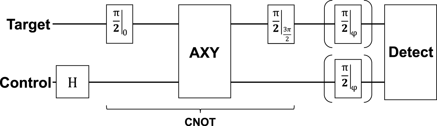
  is produced by adding a (single-qubit) Hadamard operation only, as shown in figure 5. Thus, the control qubit is initialized into an equal superposition state before the CNOT gate is applied.

Figure 5. RF sequence for a Bell state measurement. A Hadamard gate is applied to the control qubit to create an equal superposition state, then the AXY sequence framed by two  pulses with phases 0 and
  creates a CNOT gate. Additional rotations to each qubit are optionally applied for rotating the measurement basis before state read-out.
Download figure:
Standard image High-resolution imageAn entangled state shows quantum correlations when measured in different bases. As state detection is a projective measurement to the z-basis only, an additional set of RF-pulses is appended to the pulse sequence to allow for measurements in the x and y basis as well. These RF pulses map the respective populations to the z basis before shining in the laser for state selective detection. The Bell state fidelity is then reconstructed from the correlations in the x, y and z basis, respectively. Often a full parity scan is used to assess correlations in the different bases, by scanning the phase of the basis-changing pulses from 0 to 2π [41]. We reduce measurement efforts considerably by probing only at two specific rotations (in addition to the z-measurement itself, carried out without the additional, base changing RF-pulses). In particular, settings of  correspond to the x and y basis (the extreme points of the parity curve). Using these measurement results, the Bell state fidelity is determined according to [42, 43] as

with the expectation values given by

for  and measured relative frequencies
  of each of the four basis states in the respective basis. Figure 6 depicts the results of these measurements, showing the relative frequencies in the z-basis on the left and the expectation values in all three bases on the right. According to equation (9), a Bell state fidelity of 89.1(1.5)% is achieved in this experiment.

Figure 6. Results of a Bell state measurement of the state  created using the AXY gate sequence. (a) Relative frequencies of the four basis states
  , measured in the z-basis. (b) Expectation values for the x, y and z basis, derived from three similar measurement steps, when the basis is rotated before state read-out. From these, the Bell state fidelity of 89.1(1.5)% is calculated.
Download figure:
Standard image High-resolution imageFurthermore, avoiding full quantum state tomography, we can also provide a lower bound on the logarithmic negativity which constitutes a computable measure of entanglement [44]. The logarithmic negativity of a density operator ρ is defined as  where
where  denotes the partial transposition of ρ. As its exact determination would require full state tomography we follow [45] and obtain a very good lower bound based on the measurement of the correlators
  ,
,  and
and  and the determination of density matrix with the least logarithmic negativity that is compatible with the measured correlators. This minimization can be carried out analytically and yields

with  . From the measurement data of figure 6, we obtain

It should be remarked that the Bell state fidelity and logarithmic negativity reported here do not match the expected values based on the Ramsey fringe contrast reported above (figure 4). These Bell state measurements were carried out several days after the Ramsey data shown in figure 4. Immediately after the Bell state measurements discussed above, another Ramsey-type experiment was carried out that then revealed a lower contrast than was observed before. This is shown in figure 7.

Figure 7. Result of a Ramsey measurement on the target qubit, when the AXY phase gate is applied to a two ion system. The control qubit is initialized to  (red) or
  (blue), resulting in conditional phase shifts of
  with fringe contrast of
  and
and  with
with  respectively. The reduction of fringe contrast compared to the previous measurements (figure 4) matches with the observed Bell fidelity of 89.1(1.5)% and is attributed to an instability of the current experimental setup.
Download figure:
Standard image High-resolution imageThis discrepancy is due to an unexpected change in the experimental setup after having recorded the data shown in figure 4—an unstable mechanical or electric connection within the vacuum chamber is suspected to have caused variations in the electric potentials at the ion's position. It lead to a persistent change in the observed Ramsey fringe contrast.
We have two reasons to believe, that the high Ramsey fringe contrast shown in figure 4 would correlate with a high-fidelity Bell state measurement. The first being the observation, that the back-to-back measurements of Bell state fidelity (figure 6, 89.1(1.5)%) and Ramsey fringe contrast (figure 7, 92(4)% and 89(3)%) exhibit compatible results. Secondly, the two pulse sequences giving the data in figures 6 and 7, respectively, differ only by single-qubit operations, as indicated in figures 3 and 5. Since these single-qubit rotations are characterized by a typical fidelity in this apparatus of 99.98% [20], one expects them to contribute to the overall infidelity of the sequence generating a Bell state only negligibly.
The achievable Bell fidelity is expected to be limited by the Ramsey fringe contrast, which translates into the errors of the relative frequencies of equation (10) for correctly measuring the target qubit. It is therefore implied by the high-fidelity Ramsey results as shown in figure 3 that a Bell fidelity of 99% is reachable, even though it has not been independently measured, yet.
5. Robustness
We investigate in detail the resilience of the gate to several potential sources of error: the excitation of the ions' COM vibrational mode, pulse errors, and timing mismatch. Using Ramsey measurements as before, fringe contrast and phase shift serve as figures of merit for the gate performance. All of the following measurements are interleaved with additional reference measurements as shown in figure 7 and are normalized with respect to them. These reference measurements do not include the purposely added well-controlled 'error' (i.e. variations of phonon number, secular trap frequency, Rabi frequency, timing) under investigation.
Decoherence is a major obstacle for quantum logic operations. In the current experimental setup, the gate time of 6 ms faces a coherence time of  µs when no DD is applied. However, using pulsed DD preserves coherence for even longer gate times. Quantum logic operations with gate times of 30 ms have been successfully implemented [46] using this method. In case of the AXY gate, sequences of 80 or 160 pulses (AXY-16 and AXY-32 respectively) show the best results in terms of balancing decoupling and pulse errors. Increasing the number of pulses further has no benefit in gate fidelity, since the pulse errors start to become detrimental.
5.1. Vibrational excitation
Many conditional gates rely on ground state cooling of an ion chain. We investigate the effect of initial COM mode excitation on the gate performance. Different initial thermal excitations with mean phonon number  between 1.0(5) up to the Doppler cooling level, estimated to the order of 100 phonons, are achieved by placing a variable heating time after initial sideband cooling, before the beginning of RF manipulation. Given the heating rate of our setup of 0.12 phonons ms−1, the mean phonon number can be adjusted by varying the heating time accordingly. The mean phonon number
  for each setting is experimentally verified by sideband spectroscopy measurements [35].
The effect of varying the initial COM mode excitation on the phase gate can be seen in figure 8. There is no significant decrease in fringe contrast nor a change in the achieved phase shift up to  phonons as compared to an ion crystal cooled close to the ground state. While the resulting phase starts to deviate towards higher
  , the contrast is still stable with values
  90% even when no sideband cooling is applied.

Figure 8. Influence of mean thermal phonon number  of the COM vibrational mode on the resulting Ramsey fringe contrast (a) and phase shift (b) of the AXY gate. An AXY-16 sequence is applied to generate a
  phase gate, while
  is varied. This is achieved by a variable heating time before the gate sequence, after RF sideband cooling (SBC) close to the motional ground state. The last point depicts the Doppler cooled state, when no SBC is applied at all. It is estimated to about 100 phonons. The dashed line indicates the reference setting of 1.0(5) phonons, to which all results are normalized.
Download figure:
Standard image High-resolution imageVariations of the phase above a COM excitation of 10 phonons are in agreement with the reference setting within 2-3 standard deviations and hence can be considered compatible with the reference measurement. Only for the Doppler cooled state the change in phase is well outside the statistical uncertainty. From theoretical considerations, large thermal excitation could result in a Lamb-shift-type term altering the resulting phase. The phonon number
 is treated as a constant throughout the gate in theoretical simulations and the resulting shift is refocused by the DD sequence. The presence of motional heating inducing a variation of
 during the gate could turn into a constant displacement of the final phase. Only if the heating rate would increase with the phonon number, the shift would increase accordingly.
5.2. Secular axial trap frequency
The gate mechanism is based on tuning pulse timings of the AXY sequence with respect to the motional mode frequencies of the ion crystal. Changing the endcap voltages, the axial trapping potential and thus the mode frequencies can be detuned with respect to the reference setting, based on which the sequence timings are calculated. The respective secular trap frequency is measured by a method called tickling. In this method a small alternating voltage is applied to one of three available compensation electrodes around the trap center. When its frequency matches the secular frequency of the COM ion motion, the latter is excited and the crystal starts to melt. With this, we typically achieve a resolution of  Hz for the axial trap frequency ν1.
Figure 9 displays experimental results of the Ramsey contrast and phase shift achieved by the gate as a consequence of deviations between the theoretically assumed and the actual axial trap frequency. The latter is verified experimentally for each setting with the tickling method. While the contrast of the gate is not significantly affected, accurate setting of the mode frequency is crucial to match the pre-computed phase shift. Given the resolution of  Hz achieved with the tickling method, knowledge of the mode frequencies to the
  level is provided. As suggested from figure 9, this linearly translates into the phase error of the gate, i.e. infidelities below 10−4. Low pass filters with cut-off frequencies
  Hz are used to stabilize the endcap voltages, i.e. errors due to fluctuations are suppressed to below 10−5. Towards the lower endcap voltages jumps occur even in fringe contrast, indicating instabilities of the trapping potential.

Figure 9. Effect of the trap frequency on the resulting Ramsey fringe contrast (a) and phase shift (b) of the AXY gate. The axial trap frequency is varied, deliberately inducing a mismatch between the pulse timings of the AXY sequence and the motional frequencies. An AXY-16 sequence is applied to generate a  phase gate, the dashed line indicates the reference setting of
  kHz, to which all results are normalized.
Download figure:
Standard image High-resolution image5.3. Pulse errors and sequence timing
Instability of the RF power is another common source of error, since it translates directly into the Rabi frequencies of the qubit system. Here, we distinguish between two possible types of errors, which can be caused by this, as sketched in figure 10. First, we investigate pulse area errors due to a mismatch between the theoretical Rabi frequency, used to calculate the pulse widths and the experimental Rabi frequency defined by the applied RF power. This causes all pulses to differ from π rotations, while sequence timings still match the calculations. Such errors can, for instance, be caused by slow drifts of the RF power due to temperature changes of the electronics.

Figure 10. Two types of errors induced by instabilities of the RF power. The first two pulses of an AXY block are shown as an example, where the dashed lines indicate the calculated pulse width and amplitude, respectively, while the red areas sketch the actually applied pulses. (a) Pulse area errors cause all pulses to differ from π rotations, as the pulse time does not match  . Timings of the AXY sequence are still correct. (b) Re-calibration of the RF amplitudes allows for correct π rotations, at the cost of a different pulse time
  . This causes spacings
  in between pulses to differ from the calculated sequence. Center positions of each pulse defined by the sequence parameters τa
and τb
are not affected.
in between pulses to differ from the calculated sequence. Center positions of each pulse defined by the sequence parameters τa
and τb
are not affected.
Download figure:
Standard image High-resolution imageFigure 11 shows the resulting contrast and phase of an AXY-16 gate, if a mismatch is deliberately introduced to the RF power by changing the amplitude setting of the signal generator. For each point, the offset is confirmed by a separate measurement of the actual Rabi frequency. On the one hand, these results confirm the robustness of the DD pulses against pulse errors, since there is no significant effect on the measured fringe contrast. On the other hand, the phase shift is affected for mismatches  . However, keeping RF amplitudes stable to less than
  is well within current experimental limits.

Figure 11. Effect of pulse errors on the resulting Ramsey fringe contrast (a) and phase shift (b) of the AXY gate. An AXY-16 sequence is applied to generate a  phase gate, with an offset of the pulse times with respect to the ions' Rabi frequencies. Results are normalized to the reference setting of zero offset as indicated by the dashed line.
Download figure:
Standard image High-resolution imageThe second type of error is induced, when pulse area errors are minimized by re-calibration of the Rabi frequency. Pulse times are adjusted accordingly, to match the desired π rotations. As a consequence, π pulses are applied correctly, but deviations in pulse timings of the AXY sequence are introduced. While this could be counteracted by a recalculation of the sequence, it is not possible on experimental time scales, due to the required calculation times. In particular, the spacings in between pulses differ from the calculations, while their position within the sequence, defined by the parameters τa and τb , are still correct.
Simulations indicate, that in the limit of small Rabi frequencies, their value (or the duration of the pi pulses) plays a role in the accumulated gate phase, which decreases for smaller Rabi frequencies. For the parameters considered in this work, the calculated change in gate phase is small, i.e. it contributes an error  .
.
This is verified experimentally, since the results in figure 12 do not show any significant effect of such timing errors on the phase or fringe contrast, even for very large errors up to 30%. From these results it can be seen, that matching the exact pulse times to the simulations is much less critical than matching pulse times to the applied RF power.

Figure 12. Effect of errors in sequence timings on the resulting Ramsey fringe contrast (a) and phase shift (b) of the AXY gate, when an AXY-16 sequence is applied to generate a  phase gate. The ions' Rabi frequencies are shifted by changing the RF amplitudes, but pulse times are re-calibrated accordingly. This way there are no pulse errors, but the time in between the pulses differs from the pre-calculated timings by the amount of the shift in Rabi frequency. The dashed line indicates a reference setting with no such errors, to which all results are normalized.
Download figure:
Standard image High-resolution image
6. Summary and outlook
In conclusion, we have demonstrated an experimental implementation of a high-fidelity two-qubit tunable conditional phase gate in a RF-driven trapped-ion setup. The gate is generated by a specifically tuned dynamical decoupling sequence on the qubits' carrier transitions. We also use this phase gate to implement an entangling operation shown here by generation of a Bell state.
Furthermore, the effect of motional excitation of the COM mode, errors in trap frequency as well as pulse and timing errors have been investigated. The gate is particularly robust to the ions' vibrational excitation, as up to 10 phonons on the axial COM mode do not spoil gate performance in phase nor fringe contrast. Axial trap frequency and pulse errors can have an effect on the resulting phase, while errors in sequence timings do not show any deterioration of the gate performance. For the axial trap frequency, a gate infidelity  is expected from the precision obtainable by tickling measurements and low pass filtering to the 10−5 regime. Pulse errors only start to show an effect at levels
  , while state-of-the-art RF setups are capable of amplitude stabilities
  . The gate implementation presented in this work is resource efficient as only a single RF field is used per ion. Even a single-tone RF field can be sufficient by redesigning pulse sequences. This is beneficial for scalability, as it avoids limitations such as amplitude resolution and storage capacity of signal generators and amplifier power. In future setups—a planar ion trap with magnetic gradient of 120 T m−1 and improved coherence time has recently been put into operation—we expect to make use of both motional modes of the crystal and a corresponding speed-up of the gate time. In combination with the improved coherence times, considerably faster gates with gate times on the order of
  s and fidelities
  are expected from the respective simulations. Since the coherence time is now much longer than the gate time, the number of DD pulses can be reduced further to a minimum of a 20-pulse AXY-4 sequence in the future.
Acknowledgments
We acknowledge financial support from the EU Horizon 2020 Project 820314 (microQC) and from the German Federal Ministry of Education and Research under grant number 13N15521 (MIQRO). We acknowledge support by the ERC Synergy grant HyperQ (grant no 856432). P B and P H thank O Gühne for helpful discussions. J C acknowledges the Ramón y Cajal (RYC2018-025197-I) research fellowship, the financial support from Spanish Government via EUR2020-112117 and Nanoscale NMR and complex systems (PID2021-126694NB-C21) projects, the ELKARTEK project Dispositivos en Tecnologías Cuánticas (KK-2022/00062), and the Basque Government grant IT1470-22.
Data availability statement
All data that support the findings of this study are included within the article (and any supplementary files).