


Abstract
Common optical metasurfaces are two-dimensional functional devices composed of periodically arranged subwavelength constituents. Here, we achieved the positional-disorder-immune metasurfaces composed of core–shell cylinders which successively exhibit the magnetic dipole (MD) resonant, non-radiating anapole, and electric dipole (ED) resonant modes when their outer radii are fixed and the inner radii change continuously in a range. The performances of the metasurfaces under a periodically structural design are not degraded even when the positions of the cylinders are subjected to random and considerable displacements. The positional-disorder-immunity is due to the weak non-local effect of the metasurfaces. Because the multiple scattering among cylinders is weak and insensitive to the spacing among the cylinders around the ED and MD resonant modes and vanishing irrespective of the spacing at the non-radiating anapole mode, the reflection properties including the reflection phase and reflectivity of the metasurfaces are insensitive to the spacing between neighboring cylinders for this entire variation range of the inner radius. Our findings can have important implications in understanding the underlying mechanism of the positional-disorder-immunity and provide a unique approach to achieve metasurfaces with various performances robust against large positional disorders. We expect the present work to open a door for the various applications of the metasurfaces in some harsh and unstable environments.
Export citation and abstract BibTeX RIS

Original content from this work may be used under the terms of the Creative Commons Attribution 4.0 licence. Any further distribution of this work must maintain attribution to the author(s) and the title of the work, journal citation and DOI.
1. Introduction
Metasurfaces can tailor the wavefront of an electromagnetic (EM) wave into an arbitrarily desired shape by adjusting the geometrical and/or constitutive parameters of the subwavelength optical scatters [1], thereby achieving fruitful applications such as optical vortex generation [2], subwavelength focusing [3], carpet cloak [4], wavefront deflection [1], holographic imaging [5], perfect absorption [6–8], beam splitting [9] and so on. The high efficacy on the wavefront manipulation is benefited from the abrupt phase changes between the two sides of the subwavelength scatter. Apart from the Pancharatnam–Berry phase method [10], the Mie resonant excitations of low-loss dielectric scatters provide another route to realize the phase modulation [11]. Moreover, the rapid changes around the resonant peak enable the flexible control of both the magnitude and phase of the scattered EM wave [12–14]. However, to implement a full 2π phase modulation based on a single resonant mode excitation is impossible because the range of phase change is limited to π for the Lorentzian resonators [15]. Therefore, a covering of multiple resonant mode excitations is necessary for the full 2π phase modulation.
Most metasurfaces are in periodic structures [16–23]. However, the periodicity and spatial symmetry of the structure lead to a more pronounced spatial dispersion [24], and largely reduce the degree of freedom of the structure to control the scattering and transporting of the EM wave in a more flexible way, compared with the disordered metasurfaces [25–33]. And the perfectly periodic structures require much more sophisticated and precise fabrication technologies such as nano-lithographic techniques, which are time-consuming and comparatively expensive [34, 35]. Moreover, the performances of the metasurface with a periodic structure are usually sensitive to the spacing among the neighboring subwavelength constituents [36–39]. This sensitivity leads the metasurface cannot deal with the positional disorders induced by fabrications or some inevitable external forces in unstable and harsh environments.
Resonant modes can localize the scattered field near the surface of the scatter, thereby making the scattered field intensities decreasing dramatically far away from the surface. The weak multiple scattering among the scatters due to the weak scattered field away from the surfaces render the EM wave properties of the whole structure less dependent on the spacing among the scatters when they are not so close to each other [40]. As the extremest case, the anapole mode [41–46] which is pure non-radiative can even localize the scattered field totally inside the scatter. The non-radiating behavior of the anapole mode provides a new mechanism for achieving the EM wave transparency [43, 47]. Because the light is grasped inside the scatter without leaking, light–matter interaction inside the scatter can be enhanced to enable various applications of the anapole mode, such as the nonlinear effect enhancement [48, 49], nanolasers [50], and sensing [51]. Since the scattered field outside the scatters are vanishing, the multiple scattering among the scatters for the anapole mode excitation is absent irrespective of their spacing. As such, the EM wave properties of the whole structure will not depend on how the scatters which are exhibiting the anapole mode are arranged.
In this work, we achieved the metasurfaces with performances immune to a large positional disorder using one-dimensional arrays of the metallic core-high dielectric shell cylinders. The metal-dielectric core–shell cylinders can be synthesized by the combination of the electrochemically anodic aluminum oxide template method and the chemical vapor deposition method [52–56]. For a fixed outer radius, the magnetic dipole (MD) resonant, anapole, and electric dipole (ED) resonant modes of the cylinder are excited successively as the ratio of inner radius to outer radius α increases from 0.20 to 0.62. Because both the ED and MD resonant modes are involved, the reflection phase can be modulated from −π to π in this inner radius range. Around the ED or MD resonance, the modulated phase is insensitive to the spacing among the adjacent cylinders. More importantly, the modulated phase is completely independent of the spacing at the anapole mode. As a consequence, the phase modulation for this entire range of α is almost independent of the spacing. As such, the performances of the metasurfaces based on the phase modulation are robust against a large positional disorder of the cylinders.
By comparing with the metasurfaces composed of core–shell cylinders which exhibit the ED and MD resonant modes only during the full 2π range phase modulation, we revealed that the existence of the anapole mode excitation in the whole phase modulation range is significant for the positional-disorder-immunity. Although the disordered metasurfaces have been widely explored [25–33], the disorder immunity as well as the underlying physics are paid little attention. Our results may shed new light to unveil the physics of the disorder immunity when the light interacts with the positional disordered metasurfaces, broaden the researches of the optical metasurfaces from disorder toward disorder immunity, and guide us to design metasurfaces with robust performances. Usually, in some unstable and harsh circumstances, such as the outdoors under the sunshine and the battleground, positional disorders are inevitably induced, such as the local thermal expansion or cold contraction and displacements due to the mechanical impacts. Therefore, the positional-disorder-immunity will promote and improve the applications of the metasurfaces in such kind of circumstances.
2. Scattering and multiple scattering properties of the core–shell cylinders
The metallic core-high dielectric shell cylinder we considered in this paper is shown in figure 1(a), which has an inner radius r0 and an outer radius r1. The metallic core and substrate are assigned with copper in the metasurfaces. The shell is made of LiTaO3 with refractive index m and the surrounding is air. Throughout this paper, we consider that the outer radius of the cylinder is k0r1 = 0.98, where k0 is the wavenumber in the surrounding. For convenience, we define a dimensionless parameter α = r0/r1 to characterize the inner radius. The polarization of the external plane wave is parallel to the central line of the cylinder (along the z direction) and the wave vector is perpendicular to the central line (along the negative-y direction). At the incident frequency 0.38 THz, the refractive index of LiTaO3 is m = 6.44 + 0.0069i [57]. In the terahertz regime, the copper core can be regarded as the perfect electric conductor [58]. According to the Mie theory for core–shell scatters [59], the scattering, extinction, and absorption efficiencies are obtained as:


where x = k0r1 is the dimensionless size parameter in the surrounding, and bn are the Mie coefficients of the cylinder expressed as [59, 60]

Here the auxiliary functions are defined as

where Jn, Yn, and Hn are, respectively, the Bessel function of the first kind, the Bessel function of the second kind, and the Hankel function of the first kind, and k1 = mk0 is the wavenumber inside the shell.

Figure 1. (a) The coordinate settlement and the geometrical sketches of the planar metasurface and core–shell cylinder. The inner and outer radii of the cylinder are r0 and r1. The spacing between the neighboring cylinders is defined as the nearest distance between the neighboring cylinders' surfaces and noted as d. (b) SE (red) and AE (blue) of the core–shell cylinder as functions of the ratio α. (c) The contributions from different dominant modes. (d)–(f) The normalized scattering field intensity distributions. (d) and (g) the intensity distributions for a single and three identical cylinders at the MD resonant mode excitation corresponding to the point B, (e) and (h) at the anapole mode excitation corresponding to the point C, (f) and (i) at the ED resonant mode excitation corresponding to the point D. The length of the white bars are 100 μm.
Download figure:
Standard image High-resolution imageIn figure 1(b) we showed the scattering efficiency (SE) and absorption efficiency (AE) based on equations (1)–(5) as functions of α by the red and blue solid lines, respectively. The vanishing small values of the AE curve indicates that the absorption of a single core–shell cylinder can be safely neglected for most cases. In figure 1(c), we showed 2|b0|2/x, 4|b1|2/x, 4|b3|2/x which are corresponding to the contributions from the ED, MD, magnetic octupole (MO) modes, respectively [61, 62]. The contributions of Mie coefficients of other orders for SE are so weak that are ignored. There are two peaks (points A and D) and one dip (point C) for the ED mode, one peak (point B) and one dip (point C) for the MD mode, and one peak (point E) for the MO mode when α ranges from 0.01 to 0.62. The peaks of the modes correspond to the resonances of the modes. It is interesting that the ED and MD dips meet at the same point (point C) and approaches zero, meanwhile, the MO mode is vanishing small at this point. Therefore, the non-radiating anapole mode is excited at point C [44, 63].
In figures 1(d)–(f), we showed the normalized scattering electric field intensity distributions  at points B (MD resonant mode), C (anapole mode), and D (ED resonant mode), respectively. Throughout this paper, the commercial software COMSOL [64] is used for the numerical simulations. For the MD and ED resonant modes, the scattering fields are localized near the surface of the cylinders, see figures 1(d) and (f), while for the anapole mode, there is no scattering field outside the cylinder, see figure 1(e). The scattering fields outside the cylinders will determine the strength of the multiple scattering among multiple cylinders. To the zeroth order approximation, the multiple scattering strength is proportional to Eis(rj − ri), where Eis is the scattering field of the ith cylinder, ri, rj are positions of the ith and jth cylinders. Therefore, for the anapole mode excitation, the multiple scattering among the cylinders is vanishing. In figures 1(g)–(i), we plotted the normalized scattering field distributions for three identical cylinders for the MD resonant, anapole, and ED resonant modes, respectively. The cylinders are aligned along x direction with the same spacing. We can see that for the anapole excitation, the field distribution keeps invariant, while for the MD and ED resonant mode excitations, the field distributions are changed when other cylinders are close.
To further identity the anapole mode at point C in figure 1(c), we calculated the ED moment p and toroidal dipole moment t using the near fields and currents according to [44, 65]:


where r is the local coordinate, r = |r|, ω is the circular frequency of the incident wave, c is the light speed in vacuum and j is the light-induced current density expressed as

with ε0 being the vacuum permittivity, ε(r) being the position-dependent relative permittivity, and E(r) being the total electric field. The anapole occurs when p = −ik0t [44, 66, 67]. According to Equation (6)–(8), we plotted the real and imaginary parts of p and −ik0t as functions of α using the red and blue lines in figure 2(a), respectively. As we can see, both the real and imaginary parts of the p are simultaneously equal to those of −ik0t at α = 0.26 (see points F and G), which just corresponds to the anapole mode excitation as shown in figure 1(c).
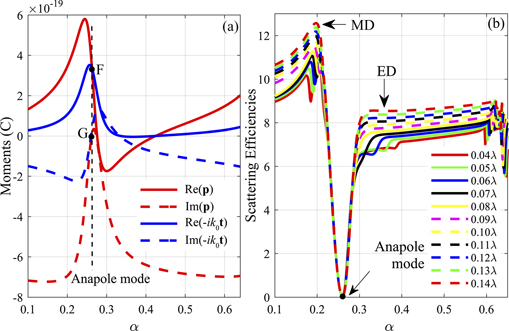
Figure 2. (a) Cartesian moments: the real part of p (red line), the imaginary part of p (red dashed line), the real part of −ik0t (blue line), the imaginary part of −ik0t (blue dashed line). (b) The scattering efficiencies of three identical cylinders with the same spacing d in the range of 0.04λ to 0.14λ.
Download figure:
Standard image High-resolution image3. Structural parameters-dependent reflection properties of the metasurfaces
We designed the reflective metasurfaces by arranging the core–shell cylinders with the fixed outer radii r1 and well chosen inner core radii r0 along the x direction on the metallic film, as schematically shown in figure 1(a).
We first investigated the reflection properties of the metasurface composed of identical cylinders arranged periodically. Figure 3(a) and (b), respectively, show the reflection phases and reflectivities as functions of α when it changes from 0.20 to 0.62 continuously for different spacing d. This range of α covers points B, C, D, and E in figure 1(c). The spacing d is defined as the nearest distance between the surfaces of neighboring cylinders, see figure 1(a). The reflection phase is defined as the phase difference between the reflection and incident waves at the top of the cylinders. It can be seen that the reflection phases cover the full 2π range (from −π to π) and the reflectivities are close to unity for all spacing ranging from 0.04λ to 0.14λ. It is worth noticing that for α = 0.26 which just corresponds to the anapole excitation, the reflection phases are invariant for all spacing. This is expected because the cylinder array is transparent for the EM wave no matter what the concentration is due to the non-radiating properties of the anapole mode. Also, the reflectivity find dips at α = 0.26. This is also expected since the absorption is enhanced as the strong EM fields are localized inside the absorptive shell when the anapole mode is excited. The depths of the reflectivity dips are just proportional to the concentrations of the arrays. What's more, for the MD and ED resonant mode excitations, because the scattering fields are decaying fast especially along the x direction, see figure 1(d) and (f), the multiple scatterings among the cylinders are very weak and insensitive to the spacing when they are not so close to each other. Consequently, for this entire range of α, both the reflection phases and reflectivities are almost the same for all spacing ranging from 0.04λ to 0.14λ, see figures 3(a) and (b).
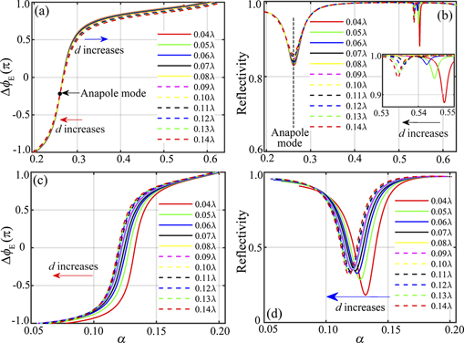
Figure 3. (a) and (c) The reflection phases ΔϕE and (b) and (d) the reflectivities as functions of the ratio α ranging from 0.20 to 0.62 (0.01 to 0.20) for different spacing d. The results are calculated assuming the cylinders are equally spaced. The arrows in the figures denote the shifting directions of the curves when the period d increases.
Download figure:
Standard image High-resolution imageIn figure 2(b), we showed the SE of three identical cylinders with the same spacing d when d varies from 0.04λ to 0.14λ. Compared with the case of a single cylinder as shown in figure 1(b), α for the ED and MD resonant modes shift slightly due to the weak coupling among the cylinders, while α for the anapole mode is invariant because of the absence of coupling. For the MD resonant mode with a higher quality factor, because the field is more localized around the cylinder, the coupling among cylinders is weaker when they are not so close. So the shift of α for the MD resonant mode is small and the phase modulation around the MD resonance depends less on the spacing, see figure 3(a). However, for the ED resonant mode with a smaller quality factor, because the field is less localized, the coupling among cylinders is stronger. Therefore, the shift of α for the ED resonant mode is more remarkable, and the phase modulation around the ED resonance is more sensitive to the spacing, see figure 3(a).
As a comparison, we also considered the case when α changes from 0.01 to 0.20. This range of α also involves the transition from the ED resonant mode to the MD resonant mode. The reflection phases and reflectivities as functions of α for different spacing d are shown in figures 3(c) and (d), respectively. We can see the reflection phase also covers the full 2π range. However, the reflectivities deviate from 1 for 0.10 < α < 0.15. This is because the backward scattering is reduced and the EM fields are more likely coupled inside the cylinders when the ED and MD moments are almost equal [68–70], see figure 1(c). What's more important, because no anapole mode is excited during this range of α, the reflection phases are shifted evidently when the spacing d changes except at α = 0.055 and α = 0.20 where the ED and MD resonant modes are excited.
4. Positional-disorder-immune metasurfaces
4.1. Magnetic mirrors
In this section, we first considered the use of the metasurfaces as magnetic mirrors [15–20, 36, 71]. One key identity of the magnetic mirror is the reflection phase  , especially, for the perfect magnetic mirrors the reflection phase is zero ΔϕE = 0 [22, 23, 72]. Due to the constructive interference, the electric field enhancement at the interfaces makes the magnetic mirrors to be significant for various applications such as molecular fluorescence [21], perfect absorbers [73], subwavelength imaging [17], photocurrent generation and surface enhanced Raman spectroscopy [74], and retroreflectors [20].
The spacing between adjacent cylinders in the magnetic mirror is first assumed to be equal. For the spacing d = 0.09λ, the perfect magnetic mirror with ΔϕE = 0 is achieved when α = 0.27 according to figure 3(a). The corresponding intensity distribution of the total electric field is shown in figure 4(a), where the constructive interference at the level just above the cylinders is clearly seen. Keeping α = 0.27 invariant, we changed the spacing d from 0.04λ to 0.14λ. The reflection phases and the reflectivities for different spacing are shown by red and blue solid lines in figure 4(b), respectively. We can see that the reflection phases are approaching zero and the reflectivities are around 0.85 for any spacing d ranging from 0.04λ to 0.14λ.

Figure 4. (a) The distribution of normalized total electric field in a period. The magnetic mirror is in a periodic structure with the spacing between the neighboring cylinders d = 0.09λ. The ratio of inner radius to outer radius is α = 0.27. (b) The reflection phase ΔϕE (red solid line) and reflectivity (blue solid line) of the magnetic mirrors in periodic structures as functions of the spacing d. (c) The reflectivities (blue triangles) and averaged reflection phases for different disordered samples. The averaged reflection phase is obtained by spatially averaging the reflection phases at the level just above the cylinders. (d) The distribution of the electric field for the plane wave incident on a disordered magnetic mirror.
Download figure:
Standard image High-resolution imageWe further designed the magnetic mirror composed of the cylinders with a large positional disorder. The spacing between neighboring cylinders are randomly distributed inside the range 0.04λ–0.14λ. The positional disorder is the deviation degree of the cylinder relative to its original position in the periodic metasurfaces. Therefore, the maximum positional disorder reaches about 55.56% for the spacing. 10 samples of disordered magnetic mirrors are considered with their reflectivities and averaged reflection phases (the reflection phase is spatially averaged along x direction) are shown by the blue triangles and red circles in figure 4(c). It is clearly seen that the reflectivities as well as the averaged reflection phases of all samples are almost the same as those of the ordered magnetic mirror (magnetic mirror with equal spacing). The normalized electric field intensity distribution of a disordered sample is shown in figure 4(d). We can see the constructive interference at the level just above the cylinders. The slight inhomogeneity of electric field intensity along x direction is mainly due to the nonuniform concentrations of the cylinders along x direction. Therefore, the perfect magnetic mirrors composed of the cylinders with α = 0.27 are robust against a very large positional disorder.
The magnetic mirror with zero reflection phase can be also realized using cylinders with α = 0.12 and equal spacing d = 0.09λ, according to figure 3(c). In figure 5(a), we plotted the corresponding normalized electric field intensity distribution. The electric field at the top of the cylinder is enhanced due to constructive interference. The inhomogeneity of electric field intensity along x direction at the level just above the cylinders is due to the strong scattering of the cylinders. However, when the spacing deviates from 0.09λ, the reflection phase will be no longer zero and the reflectivity is changed dramatically, as shown in figure 5(b). Therefore, if the positional disorder is introduced, the reflection phase will become nonzero and irregular, as shown in figure 5(c). Because of the nonuniform reflection phases and reflectivities along the x direction, the reflected wave behaves no longer like a plane wave, see figure 5(d).
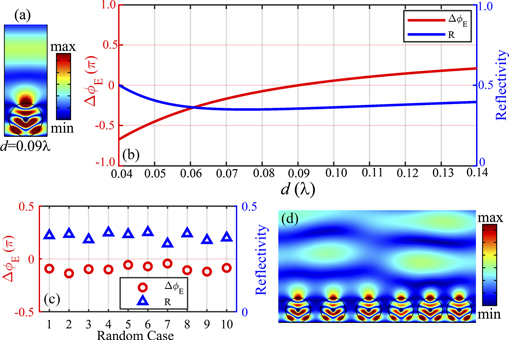
Figure 5. (a) The distribution of normalized total electric field in a period. The magnetic mirror is in a periodic structure with the spacing between the neighboring cylinders d = 0.09λ. The ratio of inner radius to outer radius is α = 0.12. (b) The reflection phase ΔϕE (red solid line) and reflectivity (blue solid line) of the magnetic mirrors in periodic structures as functions of the spacing d. (c) The reflectivities (blue triangles) and averaged reflection phases for different disordered samples. The averaged reflection phase is obtained by spatially averaging the reflection phases at the level just above the cylinders. (d) The distribution of the electric field for the plane wave incident on a disordered magnetic mirror.
Download figure:
Standard image High-resolution image4.2. Reflected wavefront deflection
The second application of the metasurface we discussed here is the reflected wavefront deflection [1, 75, 76]. Metasurfaces can reshape wavefronts through the phase discontinuities. Moreover, according to the generalized Snell's law [1], a linear phase variation along the metasurface can induce anomalous reflection and transmission. As the cornerstone of the wavefront deflection theory, the generalized reflection law is expressed as

where dϕ/dx is the phase gradient along the x direction, θ0 and θr are the incident and reflection angles. Without loss of generality, we considered the incident angle to be θ0 = 0 and the reflection angle to be θr = 20°, respectively. The metasurface we designed contains 51 cylinders with α ranging from 0.20 to 0.62. We first consider that all the spacing d between adjacent cylinders are identical and are set as 0.09λ. The inner core radii of the cylinders at different positions are designed according to equation (9). In figure 6(a), we showed the angle dependent reflection intensity S(θ) in the far field region which is defined as

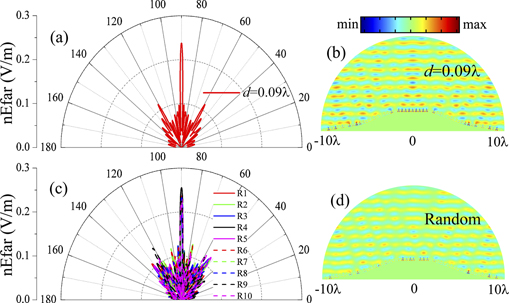
where Er is the reflection field, E0 is the amplitude of the incident wave, (r, θ) is the polar coordinate with an origin at the center of the metasurface. We can see S(θ) reaches the maximum at 110° and drop fast when away from 110°, indicating a 20° wavefront deflection. In figure 6(b), we also plotted the reflection field distribution which shows a directional transporting along the direction of 110° clearly.

Figure 6. (a) The polar plots of the reflection intensity S(θ) for the metasurface in a periodic structure with spacing d = 0.09λ. α is ranging from 0.20 to 0.62. (b) The corresponding normalized reflection wave field distribution. The arrow denotes the main propagating direction of the reflection wave. (c) The polar plots of the reflection intensity S(θ) for the 10 disordered metasurfaces with nonuniform and random spacing. (d) The normalized reflection wave field distribution of an example disordered metasurface. (e) The relative differences on the peak values of the reflection intensity S(θ) between the disordered and ordered metasurfaces (red circle line) and the angle expansions Δθn of the main lobes (from 100° to 120°) of S(θ) for the ten disordered metasurfaces (blue star line). The angle expansion Δθ0 of the main lobe of S(θ) for the ordered metasurface is shown by the blue line.
Download figure:
Standard image High-resolution imageWe then introduced the positional disorder to the metasurface. Similarly, we let each cylinder deviate from its original position with a random distance so that the spacing between the neighboring cylinders are distributed in the range of 0.04λ–0.14λ. The reflection intensity S(θ) for 10 disordered samples are shown in figure 6(c), from which we can see the reflection features for all the disordered metasurfaces are almost the same as that of the ordered metasurface, see figure 6(a). And as an example, the reflection field distribution of a disordered metasurface shown in figure 6(d) is almost the same as that of the ordered metasurface shown in figure 6(b). To quantitatively show the subtle differences on the wavefront deflection effects between the ordered and disordered metasurfaces, we depicted the relative difference on the peak values of the reflection intensities, δSn, between the ordered and disordered metasurfaces and the angle expansions Δθn of the main lobes of S(θ) of the disordered metasurfaces, in figure 6(e). The angle expansion of S(θ) of the ordered metasurface is shown by the blue solid line. The main lobes of S(θ) are from ∼100° to ∼120°, as we can see from figures 6(a) and (c). The angle expansion can be calculated as  , where θ0 = 110°. We can see the fluctuation on peak values does not exceed ±2%. Also, the angle expansions for the disordered metasurfaces are fluctuating around ∼3.50° for the ordered metasurface not exceeding 0.10°, indicating the unidirectionality of the reflection waves for the ordered and disordered metasurfaces are almost the same.
As a comparison, we also investigated the metasurfaces composed of cylinders with α ranging from 0.01 to 0.20. The core radii of the cylinders on different positions are designed according to equation (9) under the condition that the cylinders are equally spaced by d = 0.09λ. The reflection intensity S(θ) and the reflection field distribution of the ordered metasurface are shown in figures 7(a) and (b), respectively, showing a directional transporting of the reflection wave along the direction of 110°. However, when the positional disorder is introduced, because the reflection phase and reflectivity are so sensitive to the spacing, as can be seen from figures 3(c) and (d), that the reflection features are changed, see figure 7(c), and the wavefronts become curved, see figure 7(d). The relative difference on the peak values of the reflection intensities, δSn, and the angle expansions Δθn are shown in figure 7(e) by the red circle line and blue star line, respectively. We can see the reflection intensity along the direction of 110° is decreased by about 10%. This is expected since reflection along other directions arises when the positional disorder is introduced, see figure 7(c). Moreover, the angle expansions are always increasing (from ∼3.40° to ∼3.80°). Therefore, the unidirectionality is reduced.

Figure 7. (a) The polar plots of the reflection intensity S(θ) for the metasurface in a periodic structure with spacing d = 0.09λ. α is ranging from 0.01 to 0.20. (b) The corresponding normalized reflection wave field distribution. The arrow denotes the main propagating direction of the reflection wave. (c) The polar plots of the reflection intensity S(θ) for the 10 disordered metasurfaces with nonuniform and random spacing. (d) The normalized reflection wave field distribution of an example disordered metasurface. (e) The relative differences on the peak values of the reflection intensity S(θ) between the disordered and ordered metasurfaces (red circle line) and the angle expansions Δθn of the main lobes (from 100° to 120°) of S(θ) for the ten disordered metasurfaces (blue star line). The angle expansion Δθ0 of the main lobe of S(θ) for the ordered metasurface is shown by the blue line.
Download figure:
Standard image High-resolution image4.3. Carpet cloak
The last application of the metasurface considered in this work is the carpet cloak [4, 77, 78]. Covering a bump with a specially designed metasurface can suppress the unwanted scattering from the bump and make it hid from an external observer. Here, our goal is to create an ultrathin and simple carpet cloak steering the reflection beam into the normally incident beam direction. The metallic polygonal bump to be cloaked is symmetric about its central vertical line and has two tilt angles θ1 = 10° and θ2 = 20° as schematically shown in figure 8(a). For the normal incidence, to compensate the phase shift caused by the height difference h(x), the reflection phase at x should be [4, 79]


Figure 8. (a) The geometry of the bump. The bump is symmetric and has two tilt angles. (b) Schematical show of the metasurface on the bump. The horizontal spacing d is defined as the distance between the vertical tangential lines of the neighboring cylinders. (c) Reflection intensities S(θ) for the bump without the metasurface covered (black solid line) and the bump with the metasurface covered. The metasurface is composed of cylinders with α ranging from 0.20 to 0.62 the same horizontal spacing d = 0.09λ (red solid line). (d) and (e) the total electric field distributions for the uncovered and covered bump. (f) Reflection intensities S(θ) for the bump with 10 different disordered metasurfaces covered. (g) The total electric field distribution for the bump with an example disordered metasurface covered.
Download figure:
Standard image High-resolution imageThe bottom of the bump has a width of 20λ. To implement the metasurface, 51 cylinders are put along the surface of the bump with equal horizontal spacing d = 0.09λ, as shown in figure 8(b). The core radii of the cylinders are chosen based on equation (11) in conjunction with the data of figure 3(a). The normalized reflection intensity S(θ) under the normal incidence for the bump without and with the metasurface covered are shown in figure 8(c) by the black and red solid lines, respectively. When the metasurface is absent, diffuse reflection occurs. But when the metasurface is used, the normal reflection is enhanced while reflections along other directions are almost totally suppressed. Therefore, the bump with the metasurface covered behaves like air for the normally incident wave. This is also verified by the total electric field distributions shown in figures 8(d) and (e).
Consider the positional disorder is introduced that the horizontal spacing between adjacent cylinders are no longer equal but randomly chosen in the range from 0.04λ to 0.14λ. The core radii of the cylinders are not changed. The normalized reflection intensity S(θ) for 10 samples are shown in figure 8(f). We can see for all disordered samples, the reflection features are almost the same as that of the ordered case. The incident wave is almost totally reflected along the normal direction, see figure 8(g). As a consequence, the carpet cloak is valid even the large positional disorder is introduced.
We also explored the metasurface composed of cylinders with α ranging from 0.01 to 0.20. The core radii of the cylinders are designed according to equation (11) considering that the cylinders are equally spaced with d = 0.09λ. However, because the reflectivities deviate from unity and are sensitive to α, see figure 3(d), although the normal reflection is still the strongest, remarkable reflection intensities along other directions cannot be avoided, as shown in figure 9(a). Therefore, the reflection wave is no longer plane wave-like and the bump cannot be cloaked by the metasurface, see figure 9(b). These are also true for the disordered metasurfaces, as shown by figures 9(c) and (d).
Figure 9. (a) The reflection intensity S(θ) for the bump with the metasurface covered. The metasurface is composed of cylinders with α ranging from 0.01 to 0.20 and the same horizontal spacing d = 0.09λ. (b) The total electric field distribution for the bump with the ordered metasurface covered. (c) Reflection intensities S(θ) for the bump with 10 different disordered metasurfaces covered. (d) The total electric field distribution for the bump with an example disordered metasurface covered.
Download figure:
Standard image High-resolution image
5. Conclusions
In summary, we have achieved the metasurfaces with performances immune to large positional disorders by using the core–shell cylinders. The core–shell cylinders we used here will exhibit the MD resonant, non-radiating anapole, and ED resonant modes successively when their outer radii are fixed while the inner radii increase continuously, modulating the reflection phase of the metasurface from −π to π. The positional-disorder-immunity of the metasurface is due to the insensitivity of the phase modulation to the changing of spacing between neighboring cylinders. We have explored three kinds of metasurfaces for three different applications, the magnetic mirror, reflected wavefront deflection, and the carpet cloak. The inner radii of the cylinders of the metasurfaces are designed individually assuming that the cylinders are equally spaced. The numerical results reveal that the performances of the metasurfaces are not degraded even when a large positional disorder is introduced, verifying the positional-disorder-immunity of the metasurfaces. For comparison, we have also investigated the metasurfaces composed of core–shell cylinders which exhibit the ED and MD resonant modes only during the full 2π range phase modulation. Although the phase modulations at the ED and MD resonant modes are almost invariant about the spacing between the neighboring cylinders, they are shifted evidently as the spacing changes when away from the resonant modes. Therefore, the performances of the metasurfaces are degraded remarkably when the positional disorders are introduced. This indicates that the existence of the anapole mode excitation in the whole phase modulation range is key important for the positional-disorder-immunity of the metasurfaces we proposed here. We note that the core–shell cylinders can be replaced by rectangular shaped homogeneous cylinders which can also support the anapole modes by tuning the geometrical parameters to release the fabrication technique in the experiments. The positional-disorder-immune metasurfaces may find applications in unstable and harsh environments where positional disorders are usually inevitable. We also hope our work could promote the study on the metasurfaces with immunity against various disorders.
Acknowledgments
This work was supported by the National Natural Science Foundation of China (NSFC) through Nos. 12074267, 11734012 and 11904237 and Science and Technology Project of Guangdong through No. 2020B010190001.