


Abstract
We present results of a comprehensive investigation of two phenomena arising in superconductor(S)/ferromagnet(F) heterostructures of Nb on FePd with a lateral magnetic domain pattern: domain-superconductivity and spin-triplet Cooper pair generation. Resistivity measurements in a magnetic field applied out-of-plane to a Nb/FePd (S/F) sample with high magnetocrystalline anisotropy give evidence of stray field generated domain-wall- and reverse-domain-superconductivity. A corresponding bilayer comprising low magnetocrystalline anisotropy exhibits spin-triplet Cooper pair generation and a notable high variation of the S critical temperature due to spin-triplet generation (ΔTc) of 100 mK in an in-plane applied field. Using reference samples we can clearly distinguish stray field from proximity effects. The relevance of the characteristic S and F length scales related to the observed proximity effects is discussed.
Export citation and abstract BibTeX RIS

Original content from this work may be used under the terms of the Creative Commons Attribution 4.0 licence. Any further distribution of this work must maintain attribution to the author(s) and the title of the work, journal citation and DOI.
1. Introduction
Domain-superconductivity and spin-triplet Cooper pair generation are typical phenomena arising in superconductor(S)/ferromagnet(F) heterostructures [1–4], which have been proposed for the realisation of fluxonic devices for quantum computation [5] and superconducting spin valves [6, 7], respectively. Recently, several research groups have focussed on the development of applications of superconducting devices based on S/F systems [8, 9]. Superconducting parameters like the S critical temperature Tc, upper critical field  and critical current Ic can be significantly changed by confining a superconducting state on the nanometer scale. It was observed that in S/F systems with a lateral magnetic domain pattern the stray fields of the F layer will confine the superconducting states either on the domain walls (domain-wall-superconductivity, DWS) or on top of magnetic domains in reverse direction to an applied external magnetic field Hext (reverse-domain-superconductivity, RDS) [10]. DWS and RDS were examined by several groups in detail to study differences between multi- and mono-domain states [11], the influence of Hext on Tc [12], and vortex formations inside a magnetic domain pattern [13, 14]. Theoretical studies on the superconducting energy ground state of S/F structures as a function of Hext explain the reason behind the formation of DWS and RDS [15]: superconductivity preferably nucleates where the overlap of Hext with the stray fields generated by the F layer leads to a minimum in the total magnetic field strength. For Hext = 0, the stray fields are smallest at the domain walls. Hence, in zero applied field and near Tc, superconductivity will nucleate close to the domain walls [16]. An external magnetic field applied perpendicular to the sample surface instead induces RDS with a reinforcement of the superconducting state occurring when Hext exactly compensates and cancels out the stray fields generated by the F's magnetic domains in reverse direction [17].
In addition to DWS, the generation of Cooper pairs in a spin-triplet state at S/F interfaces can also have an effect on the Tc of the S layer. This occurs as result of the fact that fully-polarised spin-triplet pairs can exhibit large penetration depth inside the adjacent F layer [8, 18]. Devices based on these so called 'long-ranged spin-triplet components' (LRTC) have in fact been proposed to do spintronics in the superconducting state with low-energy dissipation [8]. Within the BCS theory [19], spin-triplet Cooper pairs with symmetric spin functions are possible components of the superconducting total wave function, but they exhibit higher energy states than spin-singlet Cooper pairs with antisymmetric spin functions [20]. Spin-triplet Cooper pairs are also generated at S/F interfaces. In particular, if the magnetization of the S/F interface is aligned with the magnetization axis of the F layer (e.g. z-axis), then spin-triplet Cooper pairs with zero net spin along the axis of the F's magnetization (i.e. with total spin Sz = 0) are generated. As initially suggested by Bergeret et al [18], however, if the S/F interface is additionally composed of a magnetic inhomogeneity on a length scale of the coherence length of the Cooper pairs, spin-triplet pairs with aligned spins (i.e. with total spin Sz = ±1 along the z-axis of the F's magnetization) can also form. Inside the F layer, spin-singlet pairs and spin-triplet pairs with Sz = 0 are short-ranged, whereas spin-triplet pairs with Sz = ±1 are insensitive to the pair-dephasing action of the F layers exchange field hex and can penetrate inside F with a large coherence length ξF [9]. Experimentally, LRTC have been observed in a variety of F/S/F pseudo-spin-valve structures [21]. In such trilayer systems, in the absence of LRTC generation, a variation in Tc between parallel (P) and antiparallel (AP) orientation of the two F's can be obtained due to the additive pair-breaking effect of the hex at the two S/F interfaces. In particular, the hex of the two F's sum up in the P state and cancel each other in the AP state, meaning that  is usually positive. The largest ΔTc value obtained to date for a fully-metallic F/S/F' heterostructure as result of the modulation of superconductivity by hex is ∼400 mK, and it was obtained by Gu et al for a Ho/Nb/Ho trilayer [7].
If a non-collinear alignment of the two F's magnetizations can be realised, which induces a non-null LRTC, then ΔTc shows a peculiar non-monotonic trend as a function of the misalignment angle between the F's magnetization θ with a dip at θ = 90° for which the LRTC amplitude is maximum. Also, the generation of an LRTC in an F/S/F' device can result in  which is the opposite of what is expected in the case of spin-singlet F/S/F' devices as discussed above [22, 23].
The effects of domain-superconductivity and LRTC on Tc to date have been investigated separately based on S/F heterostructures which have been mainly designed to study either one or the other phenomenon. A heterostructure system instead where both phenomena compete and can be tuned in their relative magnitudes would allow to investigate fundamental similarities or differences between the two effects, e.g. in the dependence of their characteristic length scales. Here, we report on the observation of both effects in Nb(S)/FePd(F) thin film heterostructures and a systematic investigation of the dependence of both effects on the strength of the perpendicular magnetic anisotropy (PMA) and the orientation of Hext (i.e. in-plane or out-of-plane). We demonstrate that samples with high PMA promote domain-superconductivity in an out-of-plane applied magnetic field. An in-plane applied field yields spin-triplet Cooper pairs, dominating the process near the coercive field in samples with low PMA. The generation of spin-triplet Cooper pairs in high-PMA samples is conjecturable, but has to be elaborated in detail by further studies (e.g. via low-temperature scanning tunnelling spectroscopy). In a low-PMA S/F system, we observe a reversible ΔTc = 100 mK due to spin-triplet generation, which is promising for the engineering of F/S/F' trilayers based on such system with even higher ΔTc.
2. Experimental
The thin film heterostructures are grown under ultra-high vacuum using a state-of-the-art molecular beam epitaxy (MBE) system from DCA Instruments Finland (base pressure of 10−10 mbar) on commercial MgO(001) substrates from MaTecK GmbH. Three types of S/F heterostructures consisting of Nb(S)/FePd(F) (namely samples SFhigh, SFlow, and SFmid) with FePd having different degrees of PMA are prepared. For details of the preparation method we refer to [24]. To ensure an epitaxial growth of FePd, first a seed layer of Cr (∼1 nm) followed by a buffer layer of Pd (∼60 nm) is grown on MgO. Additionally, two reference samples (SIFhigh and SIFlow) are grown with a thin insulating MgO layer (I) of 7.5 nm thickness between S and F to suppress proximity effects. One S/I/F structure is grown in the high-PMA state to compare with SFhigh and the other in low-PMA state to compare with SFlow, each with comparable coercive field and saturation magnetization values to their S/F equivalents (see supplementary table S1).
Ferromagnetic FePd with different degrees of PMA and magnetic domain patterns can be prepared by varying the growth parameters. We use codeposition and shuttered growth from effusion cells for the FePd layer as reported in details in reference [24]. The superconducting Nb layer is grown by electron-beam evaporation at a substrate temperature of 50 °C for SFhigh and SFmid. For SFlow a substrate temperature of 550 °C is used to improve its crystallinity. To prevent oxidation of the superconducting Nb layer, a thin capping layer (2–5 nm) of Pd is deposited on SFhigh and SIFhigh, whereas for SFlow and SIFlow a Cr capping layer is deposited. The layer thicknesses are calibrated using x-ray reflectometry (XRR) in a Bruker D8 reflectometer and are compared with results from Rutherford backscattering spectrometry (RBS) at a He-ion energy of 1.4 MeV. The superconducting Nb layer has a thickness of 40 nm, 32 nm, and 37 nm in SFhigh, SFlow, and SFmid, respectively. The thicknesses of each layer and an example of one XRR and one RBS measurement of SIFlow are given in the supplementary information (https://stacks.iop.org/NJP/22/093001/mmedia) (see table S2, figures S1 and S2, respectively). Zero-field measurements of the surface domain pattern are performed at room temperature by magnetic force microscopy (MFM) in an Agilent 5400 microscope in magnetic ac mode. Magnetic hysteresis loops are obtained using a magnetic properties measurement system (rf SQUID-MPMS) from quantum design. Conventional linear four-probe resistivity measurements are conducted using the electric transport option of a quantum design physical properties measurement system (PPMS-Dynacool) with an ac current of 10 μA and a frequency of 18 Hz. The Nb layer is contacted from the sample surface through the capping layer using a wire bonder. The morphology of the samples and the interface quality in the S/F and S/I/F heterostructures is studied using scanning transmission electron microscopy (STEM) at an accelerating voltage of 200 kV in the FEI Titan G2 80-200 CREWLEY [25] and FEI Titan G3 50-300 PICO [26] systems. Both instruments are equipped with a corrector for the strong spherical aberration of the probe-forming lens system, providing better than 0.1 nm spatial resolution.
3. Results
3.1. Characterization at room temperature
Figure 1 shows for all SF samples a schematic sketch of the magnetic domains in FePd along the out-of-plane direction (c-direction) of the L10-phase and the formation of closure domains, together with the measured domain pattern (obtained by MFM) and the magnetic hysteresis loops M(μ0Hext) at 300 K. The top (blue) layer in figure 1(a) denotes the superconducting Nb layer and the bottom is the FePd layer where the magnetic domains and their orientations are depicted with different colours and arrows, respectively. Depending on the strength of PMA, a formation of closure domains is assumed, which have also been reported earlier [27, 28] on MBE grown FePd thin films. The quality factor Q denotes the strength of magnetocrystalline anisotropy in the ferromagnetic layer: for Q < 1, the sample has an in-plane easy magnetization axis and weak PMA, whereas for Q > 1 the easy magnetization axis is out-of-plane with high PMA [24, 29]. Q is calculated by the ratio of the magnetocrystalline anisotropy constant Ku and the shape anisotropy constant Ksh, which can be determined by measuring the magnetic hysteresis in-plane and out-of-plane to the sample surface. For details we refer to [24].

Figure 1. From left to right: SF samples with high, low, and medium PMA, respectively. (a) Schematic view of the domain formation inside the FePd layer and the toplayer of Nb in direction of the c-axis of L10-ordered FePd as determined by MFM and neutron diffraction (see reference [24]). (b) (3 × 3 μm) MFM measurements at 300 K under zero field in the as-grown state of SFhigh and SFmid and after demagnetization of SFlow. (c) Hysteresis loops measured at 300 K with Hext,|| in the surface plane and Hext,⊥ perpendicular to the surface plane.
Download figure:
Standard image High-resolution imageSample SFhigh shows a maze domain structure and strong PMA with Q = 2.0 ± 0.1, see figures 1(b) and (c). Sample SFlow with Q = 0.95 ± 0.02 has an in-plane easy axis with low PMA, evolving in parallel organized stripe domains after in-plane oscillating demagnetization. Also SFmid shows a parallel formation of magnetic domains but with high PMA and Q = 1.30 ± 0.02, resulting from the combination of two FePd layers with different degree of PMA. All samples comprise a maze domain structure after saturation in an in-plane or out-of-plane magnetic field (for details on the domain configuration see reference [24]).
Figure 2(a) shows a high-angle-annular-dark-field (HAADF) STEM image of SFmid with its sharp interface between FePd and Nb, marked by the white dotted line. The red and yellow dots denote Fe and Pd atoms organized in monolayers in the L10-ordered phase, respectively. The HAADF image of the reference sample SIFhigh (see figure 2(b)) reveals that FePd and Nb layers are well separated by MgO, preventing proximity effects at the interface between the S and F layers.
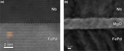
Figure 2. HAADF Scanning-TEM images of the Nb/FePd interface of (a) SFmid and (b) the reference sample SIFhigh.
Download figure:
Standard image High-resolution image3.2. Magnetotransport with out-of-plane magnetic field
Due to the high Curie temperature of FePd (∼723 K [30]), the hysteresis loop of SFhigh at room temperature exhibits the behaviour of an F thin film with a maze domain structure and with the easy axis aligned along the out-of-plane direction (see figure 3): coming from saturation, the magnetization drops fast while cylindrical domains in opposite direction to Hext ('reversed domains') nucleate. As Hext is reduced, the cylindrical domains evolve into a maze structure which results in a linear magnetization dependency [27, 31]. The inset in figure 3 shows the small but finite difference in the linear part of the hysteresis loops for its branches with increasing and decreasing Hext.
The magnetic domain structure and saturation magnetization do not change significantly in the temperature (T) range from 6 to 10 K (near the critical temperature Tc = 6.958 ± 0.001 K for SFhigh). Down to a temperature of 6 K, the saturation field is clearly visible and not altered by the onset of superconductivity. Below Tc, an additional signal is observed due to the magnetic field repulsion of the superconducting Nb layer. Here, the hysteresis loop exhibits an overlap of the ferromagnetic signal from the FePd layer and the superconducting response from Nb. Similar results were obtained for superconducting MgB2 and ferromagnetic Co composites studied by Altin et al [32], who have interpreted their hysteresis loops as a sum of respective single superconducting and ferromagnetic signals.
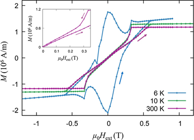
Figure 3. Hysteresis loops of SFhigh measured in an out-of-plane applied external magnetic field at 6.0 K (T < Tc), at 10 K (T > Tc), and at room temperature. The inset shows the enlarged room temperature measurement for low, positive applied fields. All hysteresis loops start in positive saturation. Subsequently, the field is ramped to negative and back to positive saturation.
Download figure:
Standard image High-resolution imageFrom the magnetization measurements reported in figure 3 we conclude that superconductivity and ferromagnetism coexist below Tc and that the domain formation and its magnetic field dependence remain unchanged. Hysteresis loops measured for SFlow and SFmid exhibit a similar behaviour to that observed for SFhigh (see supplementary figure S3).
The resistivity dependence on an out-of-plane Hext, ρ(μ0Hext), at given T for SFhigh, SFlow and SFmid is shown in figures 4(a)–(c), respectively. To confirm that the magnetoresistance features in ρ(μ0Hext) originate from stray fields, we plot in figure 4(d) the ρ(μ0Hext) curves for the high-PMA reference sample SIFhigh with an insulating layer between S and F. For this reference sample, any magnetoresistance feature in ρ(μ0Hext) must originate due to stray field effects other than to a superconducting proximity effect, which is suppressed by the presence of an I layer at the S/F interface. The measurement loops start at the negative saturation field −Hsat of the samples. Subsequently, Hext is ramped to +Hsat (red lines) and then back to −Hsat (black lines).

Figure 4. Resistivity measurements in dependence of an external magnetic field applied along the out-of-plane direction for SFhigh, SFlow, and SFmid ((a)–(c), respectively) and for the reference sample SIFhigh (d).
Download figure:
Standard image High-resolution imageFor SFhigh and its corresponding SIFhigh with high PMA, three resistivity minima are clearly visible at T across the superconducting transition: one sharp minimum near zero field and two broad minima at Hext = ±100 mT. In section 4 we will show that these minima correspond to the formation of DWS and RDS states, respectively. As T is progressively increased across the superconducting transition, the broad resistivity minima vanish and only the superconducting state near zero applied field survives. This behaviour suggests that the state of the system around zero-field has a higher Tc compared to the superconducting states corresponding to the broad minima at ±100 mT. Finite resistivity values in the DWS and RDS states are due to percolation effects and the resistivity shown in figure 4 originates from an overlap of superconducting and non-superconducting domains. As T is increased above the superconducting transition, the superconducting state is destroyed. It must be noted that, at T at the bottom of the superconducting transition, the resistivity drops to zero in the whole range between the superconducting upper critical fields ±Bc2, as the sum of the applied field and the stray fields (Bd) satisfies the condition |μ0Hext + Bd| < Bc2.
In SFmid also one sharp resistivity minimum is observed at 7 K, vanishing at lower T, as shown in figure 4(c). At 6.3 K (with Tc = 6.223 ± 0.001 K of SFmid), two broad resistivity minima appear at the same Hext = ±100 mT as for SFhigh and SIFhigh.
In contrast, the minimum near zero applied field at the highest temperature shown in figure 4(b) for SFlow is less sharp and no well resolved resistivity minima are observed at ±100 mT even at lower temperatures.
The dependence of Tc upon a constant external field μ0Hext is shown in figure 5 and is extracted from resistivity measurements in dependence of temperature ρ(T), measured independently from the magnetotransport measurements shown in figure 4. We define Tc here as the maximum of the first derivative of ρ(T). In section 4, the magnetic field dependence of Tc reported in figure 4 is compared with a theoretical model by Aladyshkin et al [15], proving that such dependence can be ascribed to DWS and RDS generated by stray fields.
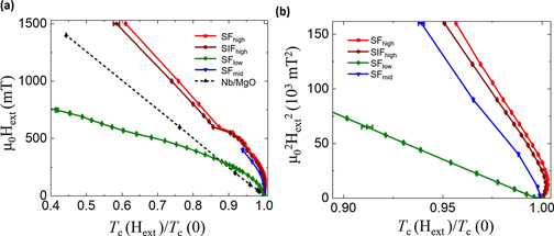
Figure 5. (a) External magnetic field applied in out-of-plane direction versus reduced critical temperature, values extracted from ρ(T) measurements in constant field. (b) Square of external magnetic field versus reduced critical temperature.
Download figure:
Standard image High-resolution imageThe data in figure 5 suggest that all samples with high magnetocrystalline anisotropy and Q > 1 show a parabolic dependence of μ0Hext near Tc, with a sharp transition into the linear T dependence expected for a bulk superconductor in an external field, at Hext ≈ 600 mT. The linear behaviour of Tc versus Hext for a bare S film is also confirmed by the data which we collect on a reference sample of Nb grown on MgO(001) substrate with similar thickness as that used for the samples SFhigh, SFlow and SFmid (see dashed line in figure 5(a)). This effect is reduced in SFlow with a smooth transition to bulk superconductivity. The parabolic temperature dependence near Tc becomes better visible in figure 5(b): after a first increase in Tc,  follows a linear temperature dependence. Unfortunately, for SFmid only measurements very near Tc were performed, but they show the same trend as for SFhigh.
From μ0Hext in figure 5(a) the highest critical field at T = 0 K for an out-of-plane applied field, Bc,⊥(0), can be extracted from the linear part measured above Hext ≈ 600 mT. From this Bc,⊥(0) value, the Ginzburg-Landau coherence length at T = 0 K parallel to the sample surface, ξGL,||(0), is calculated using Bc2,⊥(0) =  for anisotropic coherence lengths [33, 34]. Table 1 shows the Q-values, Nb-thicknesses dNb, FePd domain width DFePd (obtained by MFM), Tc values,
  , and ξGL,||(0) of all samples. We use the notation
  other than Bc2 since we observe critical field values much higher than those reported in the literature (e.g. 1 T for a 40 nm-thick Nb bare film [33]). The high
  values can be explained as due to DWS, as discussed in section 4.
Table 1. Magnetic and superconducting properties of SFhigh, SFlow and SFmid and comparison Nb/MgO (this work) and Nb/Al2O3 (obtained from [33]) reference layers. Q denotes the strength of PMA as explained in the text, dNb is the Nb layer thickness, DFePd the FePd domain width, Tc the critical temperature in zero applied field, and  the upper critical field in out-of-plane direction and ξGL,||(0) the parallel Ginzburg–Landau coherence length at T = 0 K.
| Sample | Q | dNb(nm) | DFePd(nm) | Tc(K) |  (T) (T) | ξGL,||(0)(nm) |
|---|---|---|---|---|---|---|
| SFhigh | 2.0 ± 0.1 | 39 ± 2 | 120 ± 3 | 6.958 ± 0.001 | 3.60 ± 0.03 | 9.6 ± 0.1 |
| SFlow | 0.95 ± 0.02 | 32 ± 2 | 76 ± 3 | 4.605 ± 0.001 | 1.2 ± 0.1 | 17 ± 2 |
| SFmid | 1.30 ± 0.02 | 37 ± 2 | 107 ± 3 | 6.223 ± 0.001 | 4.0 ± 0.2 | 9.1 ± 0.7 |
| Nb/MgO 1 | 41 ± 1 | 8.645 ± 0.001 | 2.51 ± 0.01 | 11.45 ± 0.07 | ||
| Nb/MgO 2 | 28 ± 1 | 8.457 ± 0.001 | 1.0 ± 0.1 | 18 ± 3 | ||
| Nb/Al2O3 [33] | 40 | 10.4 |
3.3. Magnetotransport with in-plane magnetic field
In L10-ordered FePd films, the out-of-plane axis denotes the easy axis of magnetocrystalline anisotropy. Only SFlow exhibits an easy axis in the sample surface plane as confirmed by magnetization measurements (see figure 1). Figure 6 shows the resistivity as a function of an in-plane applied magnetic field ρ(μ0Hext) with Hext applied along the 〈100〉 crystal axis at given T for all SF samples as well as for the reference sample SIFlow. The magnetic domain configuration comprises a maze domain structure after saturation, unless the sample is demagnetized. Hence, in these measurements we do not expect an in-plane magnetic anisotropy, which was confirmed by magnetization measurements performed as a function of the in-plane direction of Hext (see supplementary figure S6).

Figure 6. Resistivity measurements versus external magnetic field applied in in-plane direction for SFhigh, SFlow, and SFmid ((a)–(c), respectively), and for the reference sample SIFlow (d).
Download figure:
Standard image High-resolution imageSamples SFhigh and SFmid with high out-of-plane magnetocrystalline anisotropy (Q > 1) show only one resistivity minimum near zero field. In contrast, SFlow shows two resistivity minima and one local resistivity maximum at the coercive field Hcoerc at low temperatures. The SIFlow reference sample shows the behaviour of a conventional type-II superconducting layer with a broad resistivity minimum inside the range  and a sharp increase to the normal-state resistivity above
  . Therefore, by comparing the data for SFlow and SIFlow, we conclude that the magnetoresistance features observed for SFlow cannot be due to stray fields, but must be instead related to a genuine S/F proximity effect (unlike for the out-of-plane data reported in figure 4).
Figure 7 shows the dependence of Tc and magnetization of SFlow as function of Hext. Tc was obtained from ρ(T) measurements in a constant applied field after saturating the sample in a negative field of μ0Hext = −1.5 T. The two maxima in Tc and the minimum in Tc at Hcoerc are directly related to the minima and the maximum in ρ(μ0Hext) in figure 6, respectively.

Figure 7. In-plane applied Hext versus Tc of SFlow (left), measurements taken after saturation of the sample in negative magnetic field, and with corresponding Hext versus M data measured at T = 3.5 K (right).
Download figure:
Standard image High-resolution image4. Discussion
Summarizing the experimental results, we observe strong differences in resistivity measurements of Nb/FePd bilayer samples with different degrees of magnetocrystalline anisotropy in both, out-of-plane and in-plane applied magnetic fields. The schematic sketch of magnetic domains and closure domains on the FePd surfaces in figure 1(a) is motivated by the results of the magnetic hysteresis loops and by previous results reported in [24] where neutron scattering experiments give information on the depth-profile of the lateral magnetization orientation in the FePd layer for samples with Q > 1, and indicate small closure domains within the out-of-plane domain formation. In contrast, the hysteresis loop of SFlow exhibits a strong in-plane magnetization. As Q is smaller than 1, the easy magnetization axis is in-plane, but still out-of-plane magnetic domains are measured in MFM (see figure 1(b)). This leads to the conclusion, that a non-collinear magnetization formation as shown in the schematic sketch in figure 1(a) is present in SFlow.
The lower Tc of the SF samples compared to their reference samples with an additional insulating layer (Tc = 6.958 ± 0.001 K versus Tc = 8.241 ± 0.001 K of SFhigh SIFhigh, as well as Tc = 4.605 ± 0.001 K versus Tc = 8.433 ± 0.001 K for SFlow and SIFlow at zero applied field) suggests strong proximity coupling in the SF samples, as the penetration of Cooper pairs from S into F results in a lower value of Tc [35, 36].
In the following, we discuss the formation of DWS and RDS, as well as the generation of LRTC of Cooper pairs due to proximity effects.
4.1. DWS and RDS in samples with high PMA
Preliminary information on the formation of DWS and RDS can be obtained from resistivity measurements as a function of an external out-of-plane magnetic field ρ(μ0Hext), see figure 4. As mentioned in the introduction, superconductivity nucleates where the overlap of μ0Hext with the stray fields Bd of FePd leads to a minimum in the total magnetic field strength [10]. In zero applied field, the stray fields are smallest on top of domain walls. Hence, in zero applied field and near Tc, superconductivity will nucleate close to the domain walls [16]. An external magnetic field applied perpendicular to the sample surface induces RDS with a minimum in resistivity where the external applied magnetic field cancels out the stray fields of the magnetic domains in reverse direction [17]. This mechanism is schematically illustrated in figure 8.
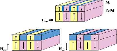
Figure 8. Sketch of DWS (top) in zero applied field and RDS (bottom) with Hext in out-of-plane direction. Blue colour denotes superconducting nucleation, whereas yellow and red represent a normal conducting state of FePd and Nb with different orientations of magnetization. In the RDS state, in the direction of applied field the toplayer of Nb is in the paramagnetic state with stray fields penetrating from the FePd layer. On top of magnetic domains in reverse direction to the applied field, superconductivity nucleates near Tc.
Download figure:
Standard image High-resolution imageNear Tc, Bc2 of Nb is in the range of the stray field values of FePd, so that superconductivity can be suppressed or reinforced through small variations in Hext. As a result, DWS and RDS can be observed as separate minima in the resistivity measurement as a function of field. In SFhigh and SIFhigh (see figures 4(a) and (d)), the higher Tc of the sharp minimum near zero field is attributed to a formation of DWS [37], similar to an increased Tc for surface superconductivity in a thin S sheath near its surface [15, 38]. As reported by Buzdin and Mel'nikov [39], in an S/F domain structured system with stray fields penetrating the S layer, superconductivity will be destroyed at high temperatures due to the pair-breaking effect of the stray fields. By lowering T across the S transition, superconductivity nucleates first at the boundaries of magnetic domains, where in-plane magnetic moments of the closure domains reduce the stray fields inside such areas. An increase in μ0Hext lowers the effect of DWS while at the same time RDS evolves due to the local reduction of stray fields generated by reversely magnetized out-of-plane domains [39]. Therefore, the three resistivity minima shown in figures 4(a) and (d) can be associated with DWS near Hext = 0 and RDS at Hext = ±100 mT. Upon a further reduction in T, superconductivity is stable above both the domain walls and the domains, resulting in one broad resistivity minimum within  .
.
Sample SFmid with medium magnetocrystalline anisotropy (Q = 1.3 ± 0.2) also clearly shows the DWS state at 7 K and the RDS states at ±100 mT at 6.3 K. At this temperature, the DWS at Hext = 0 cannot be resolved due to the broad RDS transitions (see figure 4(c)).
In SFlow no well-resolved RDS states can be observed in figure 4(b) due to the low out-of-plane magnetic stray fields (Q = 0.95). The amount of the increase of Tc in the RDS states (and therefore the strength of the resistivity minima) depends strongly on the strength of the stray fields Bd [15]. The magnetic stray fields interact with both electrons in one Cooper pair via the Lorentz force. Due to the opposite momenta of the electrons in a spin-singlet Cooper pair, the Lorentz force leads to a circulation of the two electrons around the penetrating magnetic field (so called 'orbital effect') [40, 41]. This is as well the origin for the vortex state of a type-II superconductor, where the Cooper pairs circulate around each magnetic field vortex. A measure for the change in Tc due to orbital effects is given by [15].

Here,  denotes the change in Tc due to orbital mechanisms, Tc0 the critical temperature in zero field, Bd the maximum stray field of the F layer, ξGL(0) the Ginzburg–Landau coherence length at T = 0 K and Φ0 the magnetic flux quantum. The dependence of
  on Bd can explain the difference in the evolution of RDS in the SF samples: strong out-of-plane anisotropy leads to large
  values in the Hext region corresponding to RDS (see figures 4(a) and (d)), whereas lower anisotropy results in smaller
  values (see figures 4(b) and (c)).
Different resistivity values at the same field position in up and down oriented field ramping are caused by the hysteretic response of ferromagnetic FePd with a small but finite difference in magnetization at the same field position in field increasing and decreasing state. In the RDS state, superconductivity nucleates over domains in reverse direction to Hext. Starting from +Hsat, the area of such reversed domains is smaller than the area of domains parallel to Hext if Hext > 0, and larger if Hext < 0. Yang et al [10] observed the same resistivity hysteresis caused by a magnetic hysteresis of their ferromagnetic substrate BaFe12O19 using field-dependent MFM measurements.
The parabolic temperature dependence in gure 5 can be interpreted as an indication for 2D superconducting behaviour [33], which arises when the thickness of the superconducting regions are small compared to the Ginzburg–Landau coherence length ξGL or the effective London penetration depth Λ of the thin Nb film [20, 42]. DWS can account for such behaviour: since the rotation axis of Cooper pairs is defined by the field direction, size constraints of the superconducting state in an out-of-plane applied field are given by lateral structures such as domain walls with a size smaller than the superconducting coherence length ξGL(Tc). At about 600 mT, the saturation magnetization of the magnetic domain structure in the FePd layer is reached (see figure 3, field increasing branch) and the domain-superconductivity of SFhigh, SIFhigh and SFmid turns sharply into bulk superconductivity. The smooth transition of SFlow to bulk superconductivity in figure 5 originates from the non-collinear magnetic moments in this sample.
A confirmation of the existence of isolated DWS and RDS states can be derived from the dependence of Tc on μ0Hext as shown in figure 5(a). If the Ginzburg–Landau superconducting coherence length, a measure of the Cooper pair size, near Tc is smaller than half the domain size DFePd, superconducting nuclei in the DWS and RDS states are well separated. Following [43], ξGL(Tc) can be calculated by (2):

Here, ξGL,ref(0) is the GL coherence length at T = 0 K and Tc,ref the critical temperature in zero field of the reference samples Nb/MgO.
For SFhigh and SFmid the condition 2ξGL,||(Tc) < DFePd is fulfiled, and isolated DWS/RDS is possible. In SFhigh 2ξGL,||(Tc) = 54.4 ± 0.5 nm is much larger than the estimated Bloch wall width of  nm [44] with A = 10−11 J m−1 for FePd thin films [45] and Ku = 1500 ± 200 kJ m−3 calculated from the hysteresis loops [24]. For a confinement of superconductivity on the domain walls this result supports a 2D superconducting behaviour as discussed above. From a comparison between ρ(μ0Hext) measurements of SFhigh and its reference sample SIFhigh (see figures 4(a) and (d)), we argue that the magnetoresistance features observed in these samples originate from stray fields and we support this claim by fitting a model derived from Aladyshkin et al [15]. Here, an S thin film is placed onto an F with PMA. The model is based on a phenomenological Ginzburg–Landau approach and takes into account the effect of an applied Hext. The reported DWS in reference [15] is purely related to the stray fields generated by the F layer. The critical temperature for this case is given by:

with b =  . Emin is an eigenvalue of the Ginzburg–Landau equation for the highest possible applied field with superconducting nucleation in special boundary conditions [38], in this case given by the domain-wall-superconductivity. The calculation is based on a model where the domain wall width DDW is much smaller than the Ginzburg–Landau coherence length: DDW ≪ ξGL [15]. Figure 9 shows μ0Hext(Tc) for SFhigh close to Tc and the corresponding fit to equation (3). At μ0Hext = 0 mT in figure 9, Tc increases due to DWS over Bloch domain walls and closure domains with finite thickness, which are not assumed in the fit to equation (3).
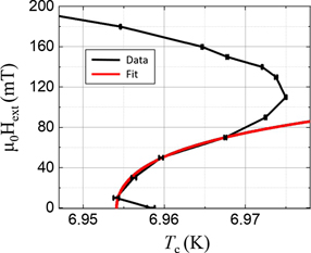
Figure 9. External magnetic field applied in out-of-plane direction versus critical temperature of SFhigh (black) and the respective DWS-Fit (red). The measurements were taken after saturation in negative magnetic field.
Download figure:
Standard image High-resolution imageThe maximum stray field Bd = 108 mT corresponds to the minimum of the field increasing branch of ρ(μ0Hext) in figure 4(a) and is given as fixed parameter in the fit. A rough estimation of the stray field strength of FePd on the Nb surface (using equation (1) in the supplementary information from a model given by [46] with z = 40 nm distance, see figure S4) yields a value of Bd = 230 mT, which is higher than the measured value of Bd = 108 mT. This can have several reasons, e.g. a reduction of field penetration due to the superconducting screening. Also, the long-range order of the FePd L10-phase is incomplete as demonstrated by the HAADF STEM measurements. In figure 2(a) on the left side of the FePd phase, the layered structure of the L10-phase with Fe and Pd monolayers is clearly visible, whereas on the bottom right it cannot be distinguished between Fe and Pd. It indicates a planar defect, which is inclined to the observation direction. In figure S5 in the supplementary, a stacking fault between Fe and Pd planes from the left to the right part of figure S5 indicates the existence of further lattice defects reducing the long-range order of the L10-phase in the FePd layers. Another possible reason for this discrepancy in Bd is that the model used for stray field computation assumes infinitely-thin domain walls, which does not strictly apply to our FePd films.
All fit parameters are shown in table 2. The fitted value of Emin = 0.32 ± 0.04 is slightly lower than for surface superconductivity with Emin = 0.59 [38]. Emin can be converted into the highest critical field  by
by  , with α being the first expansion coefficient from the Ginzburg Landau theory. Following the well known relation Bc3 = Bc2/Emin = Bc2/0.59 for surface superconductivity [38], this results into a higher critical field than for conventional surface superconductivity. Yang et al [10] observed a value of Emin = 0.37 for the nucleation of DWS, using the same model. They explained the difference to the surface superconducting value of Emin = 0.59 with their high domain wall width of DDW = 200 nm, which exceeds ξGL, whereas the model is based on DDW ≪ ξGL [15]. It shows that DWS with both, large and small domain wall width, can be described by equation (3), and that Emin for DWS differs slightly from Emin for surface superconductivity. Assuming that in the resistivity measurements the obtained critical field
  is related to the surface critical field Bc3, this can explain the high values of
  in table 1.
We conclude that the observed effects in figure 4 for SFhigh and SFmid in an out-of-plane applied magnetic field are arising from stray field generated, isolated DWS and RDS states. The higher Tc of the S/I/F structure compared to the S/F structure of SFhigh clearly indicates a proximity coupling [35, 36], but the magnetoresistance behaviour can be purely explained based on DWS and RDS states other than based on spin-triplet generation.
Table 2. Fit parameters extracted from Tc(Hext) of sample SFhigh for a model assuming DWS-like behaviour.
| Parameter | Value |
|---|---|
| Tc(0) | 6.954 ± 0.001 K |
 | 0.15 ± 0.04 K |
| Emin | 0.32 ± 0.04 |
4.2. Spin-triplet Cooper pair generation
For an external magnetic field Hext applied in the sample surface plane, no magnetoresistance features related to DWS can be observed. In figure 6, only SFlow exhibits one sharp resistivity maximum near the coercive field Hcoerc, which cannot be observed for the samples SFhigh, SFmid, and the reference sample SIFlow in the same applied field orientation.
Zdravkov et al [22] have measured the resistivity versus field characteristics in an S/F1/F2 spin-valve structure and predicted a sharp maximum in ρ(μ0Hext) at Hcoerc of their sample due to the generation of LRTC (as defined in the introduction), which exhibit the highest density at Hcoerc. This resistivity maximum corresponds to a minimum in Tc and arises due to the lower Tc value of LRTC compared to spin-singlet Cooper pairs in such a system [36]. In general, a transition of Cooper pairs into the proximity coupled layer lowers the Tc value [47] for both, spin-singlet and spin-triplet Cooper pairs. However, due to their spin alignment LRTC exhibit larger penetration depths ξF into the F layer. In an S/F1/F2 spin-valve, Fominov et al [36] predicted an additional reduction in Tc compared to the S/F1 bilayer for a non-collinear alignment of F1 and F2 which generates LRTC with Sz = ±1 and large ξF. In literature, different designations for ξF are used. Originally, ξF was defined by de Gennes [47] as 'coherence length'of Cooper pairs inside the proximity coupled layer. Other authors refer to ξF as 'characteristic length of superconducting correlation decay' [3] or 'penetration depth into F' [48], as it is used here.
The ρ(μ0Hext) measurements and μ0Hext(Tc) of SFlow in this work (see figures 6 and 7, respectively) show exactly the same sharp resistivity maximum and a minimum in Tc at Hcoerc as observed by Zdravkov et al [22]. Sample SFlow consists of high in-plane magnetic moments and low PMA, still showing a lateral magnetic domain structure. This indicates the formation of large closure domains and non-collinear magnetic moments as shown in the schematic drawing of figure 1(a). The equilibrium lateral domain thickness of SFlow was determined by MFM at room temperature to be DFePd(SFlow) = 76 ± 3 nm. This is larger than the Cooper pair coherence length near the critical temperature of SFlow with ξGL,||(Tc) = 27 ± 4 nm (obtained from equation (2)), so that the magnetic inhomogeneity existing in SFlow can affect the superconducting parameters. The non-collinear alignment favours the generation of LRTC as discussed above. In contrast to Zdravkov et al, only one F layer, however, is present in our samples. Still we argue that LRTC with Sz = ±1 are generated with highest density at Hcoerc as a result of the non-collinear magnetic texture present in our F films. They penetrate into the F layer over long distances and lower the density of spin-singlet pairs in the Nb layer, resulting in a lower Tc value [23].
The assumption of a generation of spin aligned triplet Cooper pairs in SFlow is additionally supported by the results of the reference sample SIFlow, which helps rule out other possible explanations for the resistivity maximum at Hcoerc. Following Zdravkov et al [22], the magnetic domain formation or the generation of Abrikosov vortices with vortex movements in an applied field could also cause local maxima in ρ(μ0Hext). Both effects would be stray field generated, as vortices in a sufficiently thin Nb layer can only form in the out-of-plane direction (in our S/F bilayers, vortices could be generated by stray fields in the unsaturated F layer). The stray fields should still penetrate through the 7.5 nm thick insulating MgO layer, whereas proximity effects are suppressed by the insulator. The ρ(μ0Hext) curves of SIFlow show only a conventional suppression of superconductivity due to an applied field, as in a bare S layer. As a result, a stray field origin of the maximum in ρ(μ0Hext) at Hcoerc of SFlow can be ruled out.
The measurements in an in-plane applied field indicate as well a possible spin-triplet Cooper pair formation in samples of higher anisotropy: while no local maxima at Hcoerc are observed, both SFhigh and SFmid show a kink in ρ(μ0Hext) at field values near to the local maxima in ρ(μ0Hext) of SFlow. This can be a possible sign of spin-triplet generation with lower density compared to SFlow, and possibly also arising from the magnetic inhomogeneity due to closure domains forming between Nb and FePd.
In summary, we conclude that LRTC are generated at the S/F interface of SFlow due to proximity effects between the S layer and the lateral inhomogeneous magnetization of the F layer, with a width of magnetic domains larger than the Cooper pair coherence length of SFlow near Tc. The highest density of LRTC in relation to spin-singlet Cooper pairs is reached at the coercive field, where the magnetic moments acquire a maximum non-collinearity. This results in a ΔTc as high as 100 mK in SFlow between the resistivity minima and the local maximum at Hcoerc (see figure 10). However, the resistive transition widths in figure 10(b) are of the same order of magnitude as ΔTc. In comparison, the resistive transition widths as also the maximum ΔTc of SFhigh in an out-of-plane applied field of data shown in figure 9 are an order of magnitude smaller than in SFlow as can be seen in figure S7 in the supplementary information.

Figure 10. (a) In-plane applied Hext versus Tc of SFlow, with data extracted from ρ(T) (b). Colour marks in (a) denote the applied fields during the measurement of ρ(T) in (b). The reported ΔTc = 100 mK belongs to the measurements taken at Hext = −100 mT and Hext = +17.5 mT. Red arrows denote the direction of change in Tc with increasing applied field.
Download figure:
Standard image High-resolution image
Large differences in the critical temperature under application of small applied fields are crucial for the engineering of spin-valve devices operating at cryogenic temperature which can switch between a high-Tc and a low-Tc state. Up to now, the highest reported reversible ΔTc for fully-metallic F/S/F' trilayers is about 400 mK in a Ho/Nb/Ho spin valve structure [7]. As ΔTc can raise significantly in F/S/F' trilayer structures compared to respective S/F bilayers, our value of 100 mK in the Nb/FePd bilayer has a great potential as starting point for the fabrication of F/S/F' trilayers with even larger ΔTc values.
5. Summary and conclusion
An extensive study on domain-superconductivity as well as spin-triplet Cooper pair generation with Sz = ±1 in a conventional superconductor system was conducted on several S/F and S/I/F heterostructures consisting of Nb/FePd with varying degree of PMA and a lateral magnetic domain configuration. We have shown that both effects can arise on the same base of materials depending on the strength of PMA and the orientation of an external magnetic field. Thereby, the domain-superconductivity emerges in samples with high and medium PMA in an out-of-plane applied field due to stray fields of the ferromagnet. This is confirmed by theoretical models based on the Ginzburg–Landau approach and assuming stray field generated DWS. Spin-triplet Cooper pairs with Sz = ±1 were predominantly verified in the low-PMA bilayer in an in-plane applied field. The generation of spin-triplet pairs can also be hypothesized in the samples with high and medium PMA, but this would require further experiments (e.g. low-temperature STM) for its confirmation.
The domain-superconducting effect can be exploited for tailoring the superconducting parameters like the critical temperature, field, and current on the nanoscale by applying small magnetic fields, for example to guide vortices in fluxonic devices. Long-ranged spin-triplet Cooper pairs with Sz = ±1 in materials with high ΔTc can be utilized in superconducting spin-valve devices. The reported ΔTc = 100 mK in the S/F bilayer with low PMA is a significant large value for an S/F bilayer with capability for higher ΔTc in F/S/F' trilayer systems based on this structure.
Acknowledgments
The authors thank Dr. M Waschk, Dr. S Schröder, and P Schöffmann, from Forschungszentrum Jülich GmbH, Jülich Centre for Neutron Science (JCNS-2) and Peter Grünberg Institut (PGI-4), JARA-FIT, 52425 Jülich, Germany, for helpful discussions and guidance in the initial stages of the project.