


Abstract
High-quality lithium niobate (LN) thin-film microresonators provide an ideal platform for on-chip nonlinear optical applications. The strict phase-matching condition should be satisfied for an efficient nonlinear optical process, which requires dispersion engineering with an LN microresonator. However, this is challenging in single microresonator, resulting from the fabrication error. Here, we demonstrate strong nonlinear effects in a photonic molecule (PM) structure composed of two strongly coupled lithium niobate microdisks. The size mismatch of the microdisks enables phase matching by employing coupling-induced frequency splitting to compensate for the material and geometric dispersion. With a continuous wave excitation, rich nonlinear optical phenomena including cascaded four-wave mixing and stimulated Raman scattering were observed around the second harmonic signal. Meanwhile, an ultra-high four-wave mixing absolute conversion efficiency of 14% as obtained when the second harmonic signal power is at microwatts level. The LN PM is of great potential for applications in nonlinear integrated photonics.
Export citation and abstract BibTeX RIS

Original content from this work may be used under the terms of the Creative Commons Attribution 4.0 licence. Any further distribution of this work must maintain attribution to the author(s) and the title of the work, journal citation and DOI.
1. Introduction
The development and commercialization of lithium niobate on insulator (LNOI) thin films have been making a strong impact on the photonic integrated circuit, which has allowed the production of various photonic structures of high optical nonlinearity (d33 ≈ 27 pm V−1) and electro-optic (EO) tunability in a scalable manner [1–4]. In particular, the LNOI has provided an ideal platform for the fabrication of high-quality (high-Q) on-chip lithium niobate (LN) microresonators [5–7] of which the Q factors have approached that of LN resonators fabricated by mechanical polishing and shaping [8]. Applications of such high-Q microresonators include classical and quantum light sources [9–12], light modulators [13], optomechanics [14, 15], and integrated photonic systems [16]. The properties of high-Q factor and small mode volume V render whispering-gallery-mode (WGM) based microdisk resonator a good candidate for nonlinear frequency conversion since the threshold is often in proportion to V/Qn (The nth order nonlinear optical process). However, the material and geometric dispersion of microdisk resonators lead to an inhomogeneous free spectral range (FSR) [17–19]. Thus, the phase matching is particularly challenging in a high-Q single small microcavity, due to the narrow linewidths of cavity resonances with large FSRs [18, 20]. To date, a variety of methods have been proposed to solve this problem, such as using the birefringence effect [21], intermodal dispersion [22, 23], and engineering group-velocity dispersion (GVD) [24–26]. However, these methods can impose severe restrictions on wavelength and mode volume while conceding unnecessary fabrication complexity. Fortunately, the difficulty in phase matching for the microdisk resonator can be addressed by a photonic molecule (PM) structure composed of two coupled microdisks [18, 27]. When two individual microdisks are strongly coupled with each other, the additional frequency shift induced by mode coupling can compensate for unequal FSR originated from the material and cavity dispersion, enabling phase matching. The four-wave mixing (FWM) has been demonstrated in two coupled silicon microdisks lacking second-order nonlinear coefficient [18], where the relative low Q factor relaxing the difficulty of phase matching, however, limits the conversion efficiency.
Here we demonstrated the fabrication of a PM structure by combining femtosecond laser micromachining and FIB milling. The PM consists of two high-Q LN microdisks with a gap distance of 130 nm. Remarkably, we notice that the microdisk PM exhibits unique mode features, giving rise to rich nonlinear optical processes including cascaded FWM and stimulated Raman scattering (SRS) around the second harmonic (SH) signal. The measured FWM conversion efficiency, to the best of our knowledge, is the largest in an LN microresonator to date. This indicates that PM composed of multiple microdisks with size mismatch offers an effective and easy means for compensating material and cavity dispersion, which are critical for realizing efficient nonlinear optical processes in the LN microdisks.
2. Experiment
2.1. Fabrication of coupled lithium niobate microdisks
Figure 1(a) illustrates the three procedures in the fabrication of the LN microdisk PM. In this investigation, a commercially available X-cut LN thin film (NANOLN, Jinan Jingzheng Electronics Co., Ltd) was used [2]. The LN thin film with a thickness of 700 nm was bonded to a 2 μm thick SiO2 buffer layer coated on an LN wafer. To define the LN microdisk PM, the primary structure using femtosecond laser micromachining was first patterned. Details of the fabrication process can be found in reference [5]. The LN wafer was immersed in water to minimize the contamination from the debris produced by femtosecond laser ablation, as the water prevented the debris from re-deposition on the surface of LN disks. The primary structure (i.e., the peanut-shaped structure shown at the left bottom corner of figure 1(a) was slightly larger than the designed LN microdisk PM. In particular, the two microdisks were connected as the spatial resolution of femtosecond laser ablation could not meet the narrow gap fabrication requirement. In the second procedure, the focused ion beam (FIB) milling was carried out in an FEI Helios NanoLab 600 Dual Beam system with a beam current of ∼500 pA. The pattern of FIB milling following two white circles was to define the boundary of microdisks, as shown in the middle of the bottom row of figure 1(a). In the last procedure, the fabricated structure was immersed in a buffered hydrofluoric acid solution (BUFFER HF IMPROVED, Transene Co., Inc.) to form pedestal structures beneath the LN microdisks.

Figure 1. (a) Fabrication procedures of a PM composed of two LN microdisks: water-assisted femtosecond laser ablation, focused ion beam (FIB) milling and hydrofluoric acid wet etching. The black arrow shows the optic axis of the LN thin film. (b) The SEM image of the LN microdisk PM. (c) The zoom-in SEM image of the edge of the large microdisk, indicating a partial freestanding disk with a smooth sidewall. (d) The SEM image of the cross-section at the coupling point of a typical PM shows a gap distance as small as 130 nm.
Download figure:
Standard image High-resolution imageFigure 1(b) shows the scanning electron microscope (SEM) image of the PM composed of two microdisks with diameters of 25 μm and 35 μm, respectively. The asymmetric structure is chosen so that the resonant frequency of certain WGMs in two microdisks may match each other due to the Vernier effect, while the precise fabrication of two identical microresonators is highly challenging [28]. The zoom-in SEM image of the edge of the microdisk presented in figure 1(c) shows the smooth sidewall with a taper angle of 8°34', which is typical in microstructures fabricated with FIB. The gap width between the two disks strongly affects the coupling strength. In our experiment, the gap of the PM is designed around 150 nm so that the two disks are in the strong coupling region. Figure 1(d) shows the cross-section at the coupling point of a typical microdisk PM cut by FIB after the deposition of a thin layer of platinum (Pt) for protection. And the width of the gap between the two disks is measured to be ∼130 nm.
2.2. Characterization of the nonlinear optical processes
Figure 2 schematically shows the experimental setup for investigating the nonlinear phenomena in the fabricated LN microdisk PM. Coupling light into and out of the PM was achieved by bringing a 0.9 μm-diameter fiber taper in close proximity to the periphery of the smaller microdisk [29]. The coupling efficiency was adjusted by controlling the relative position between the fiber taper and the microdisk. A swept spectrometer (Model 4650, dBm Optics Inc.) with a continuous-wave tunable diode laser (Model 688-LN, New Focus) was used to characterize the optical mode distribution of the PM. The tunable laser has a narrow linewidth of 10 MHz and a spectral range from 1510 nm to 1620 nm. To excite the nonlinear processes in the PM, the laser power was boosted by an erbium–ytterbium doped fiber amplifier (EDFA) to serve as the pump source. The optical power and polarization of the pump laser beam were adjusted by a variable optical attenuator (VOA) and an in-line fiber polarization controller (Thorlabs, Inc., FPC562), respectively. A 50:50 fiber coupler was used to monitor the power of the pump laser. To investigate the nonlinear optical signals generated in the PM, the image of microdisk PM was projected on the entrance slit of a spectrometer (Shamrock SR-303i-B, Andor Technology Ltd.) using a 20× objective lens with a numerical aperture of 0.25, and the emission from the outside boundary of the large microdisk was measured by the spectrometer. Two pieces of short-pass dichroic mirrors (DMSP1180, Thorlabs, Inc.) were used to block the pumping laser during the spectral measurements in the SH wavelength range. To determine the polarization of the nonlinear optical signals, a calibrated wire grid polarizer was inserted between the short-pass filters and the spectrometer. In addition to the spectral analysis, one charge-coupled-device (CCD) camera was installed above the PM to monitor the nonlinear processes in the PM, respectively, as shown in figure 2.

Figure 2. Experimental setup for investigating the nonlinear processes in the LN microdisk PM. Inset with blue border: optical micrograph of the microdisk PM when the SH wave was generated.
Download figure:
Standard image High-resolution image3. Results and discussion
To investigate the resonance in the X-cut LN microdisk PM, the transmission spectrum of the individual disk was measured by coupling a fiber taper with either one. In the measurements, the incident tunable laser power was limited to 200 μW to avoid nonlinear effects. Figure 3(a) shows the transmission spectra around 1565 nm at 53 °C, with the red and black curves representing the spectra obtained by coupling the fiber taper with the large and small disk, respectively. The overlaps of sharp dips in the curves indicate the existence of resonant modes in both microdisks with the same frequencies. And if a strong coupling is realized, these dips will split into twin-dip structures in both curves. Figure 3(b) shows the magnified spectra indicated by an arrow in figure 3(a). Coincident twin-dip structures can be observed around 1565.46 nm in both curves with the splitting of 1.98 pm, which discloses the strong coupling in the PM structure. The Lorentz fitting curves (the blue curve and green curve in figure 3(b)) indicate a pair of coupled modes with Q factors of 5.1 × 10⁶ and 2.6 × 10⁶, respectively.

Figure 3. (a) Transmission spectra of the two disks in a PM. The red and black curves were obtained by coupling the fiber taper with the large and small disk, respectively, as shown in the inset. (b) The twin-dip structures around 1565.46 nm disclosing pronounced mode splitting. The Lorentz fittings indicate Q factors of 5.1 × 10⁶ (blue dash curve) and 2.6 × 10⁶ (green dash curve) for the two modes, respectively.
Download figure:
Standard image High-resolution imageWhen the pump laser was tuned to one of the dips at 1565.46 nm with increased power, nonlinear spectra near the SH wavelength were observed, as shown in figure 4(a). When the pump power was set at 10.4 mW, only the SH peak at 782.73 nm was detected. The polarization measurements of the pump and SH wavelength are quasi-transverse magnetic (TM) and quasi-transverse electric (TE) mode, respectively, the nonlinear coefficients utilized are d22 and d31 [9]. When the pump power was increased to 14 mW, two equally spaced FWM peaks emerged symmetrically around the SH mode, of which the wavelengths are determined to be 778.09 nm (F1) and 787.37 nm (F2), respectively. As revealed by figures 4(a) and (b) that with an increase of the pump power, a cascaded FWM process occurred, further giving rise to the generation of the waves peaked at 773.44 nm (F3) and 792.01 nm (F4). Meanwhile, an ultra-high FWM conversion efficiency PF1/PSH (∼14%) was revealed as shown in figure 4(b) when the SH signal power was μW level. Furthermore cascaded Raman scattering was observed with Raman shifts of 580 cm−1, 581 cm−1, and 252 cm−1, as indicated by the Raman peaks R1, R2 and R3 in figure 4(b), respectively. The high Stokes wave intensities (indicated by the comparison with the SH signal) indicate the occurrence of stimulated Raman scattering. The cascaded FWM and Raman scattering processes in the SH wavelength range were confirmed by checking the spectrum around the fundamental wavelength. As shown in the inset of figure 4(b), no pronounced FWM or Raman peaks were visible in the vicinity.

Figure 4. (a) Nonlinear spectra generated near the SH wavelength at the pump powers of 10.4 mW, 14 mW, 17.1 mW, and 21.9 mW. (b) Spectrum at the pump power of 23.2 mW. Left inset: detailed FWM peaks, right inset: spectrum near the pump wavelength, showing that there are no visible nonlinear peaks in the vicinity.
Download figure:
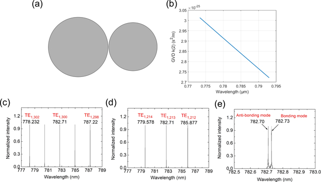
Standard image High-resolution imageSince all the nonlinear spectral measurements mentioned above are carried out by collecting the signals from the large disk whilst the pump laser is coupled into the PM from the small disk, it is unambiguous that the two disks are efficiently coupled to each other around the SH signal. The top view optical micrograph in the blue border inset of figure 2 also provides a solid proof that mode coupling between the two microdisks has been achieved in the microdisk PM around the SH wavelength. One interesting phenomenon is that the FWM spaced by 2 FSRs is observed, while there is no obvious nonlinear optical signal for the FWM spaced by one FSR. We believe this is originated from the strong coupling in the PM. To have a better understanding of the coupling strengths of two microcavities and the microcaivty in experiment is fabricated to be very thin (700 nm), 2D finite-difference time-domain calculations considering a PM by 35 μm and 25.02 μm diameters and an inter-gap of 130 nm have been performed. Here the diameter with 35 μm of large microcavity is measured by SEM, provided that SEM provides a high enough resolution. Meanwhile, the 25.02 μm diameter of small microcavity is verified by slightly adjusting the mirocavity modes around 25 μm diameter into resonance to achieve strong mode coupling. The coupled PM with a measured diameter of 35 μm and 25.02 μm is shown in figure 5(a). Figure 5(b) shows the GVD of the large microcavity, showing that the FWM signal can not be generated in a single large microcavity due to the positive dispersion. Figures 5(c) and 5(d) show the uncoupled resonance frequency of large microcavity and small microcavity, respectively. Five adjacent modes of the large microcavity show resonant wavelengths as 778.232 nm, 780.463 nm, 782.710 nm, 784.963 nm, and 787.22 nm, respectively. Efficient FWM can not exist in these modes as they are not equally spaced in frequency. The small microdisk shows a resonant wavelength as 782.710 nm, which is degenerate with one of the modes in large microdisk. When the two cavities are placed with a gap of 130 nm, strong coupling is realized and the degenerated modes split to two modes at 782.70 nm (anti-bonding mode) and 782.73 nm (bonding mode), as shown in figure 5(e). Consequantly, efficient FWM can be realized between the modes at 778.232 nm, 782.70 nm, and 787.22 nm as the phase-matching condition is satified. However, the two modes that are one FSR away from the anti-bonding mode are not equally spaced in frequency. The numerical simulation clearly illustrates that the mode splitting induced by strong coupling provides a degree of freedom to compensate the material and geometric dispersion so that phase-matching condition can be restored. Though the larger overlap of fundamental mode of the pump and the signal combined with the high Q ensure a higher nonlinear conversion efficiency, however, the modal splitting induced by mode coupling cannot be directly tuned once the device is fabricated. Fortunately, the resonance of individual microdisk can be tuned by integrated microelectrodes.
Figure 5. (a) Proposed microcavity geometry of coupled PM. (b) The group velocity dispersion of large microcavity. The simulated normalized resonant peaks of the large microcavity, the small microcavity, and the mode splitting due to strong coupling are presented in (c), (d), and (e), respectively.
Download figure:
Standard image High-resolution image
4. Conclusion
In conclusion, we have successfully fabricated the LN microdisk PM structure composed of two microdisks with a size mismatch for compensating the material and geometric dispersion in a single microdisk. We also show that various types of nonlinear processes can be efficiently excited in the PM, and an ultra-high FWM conversion efficiency of 14% is obtained when the SH signal is only μW level. Compared with the dispersion engineering for generating Kerr frequency combs based on single LN microresonators [30], the phase matching scheme we demonstrated here has 3 key advantages. First, the working band of the FWM based on the mode splitting in PM is flexible. For a single micordisk, control of GVD in the anomalous dispersion regime in the 780 nm band is quite hard to achieve by than that in the 1550 nm band since the LN crystal experiences a strong material dispersion. In the PM, the distribution of the super-modes can be easily engineered over the whole transmission window of the LN crystal by tuning the geometry of the coupled microdisk. Second, it provides high-precision manipulation of the phase-matching condition only involving a few certain modes. The FSR of the other modes is unaffected. Third, it possesses a higher tolerance in fabrication error. The compensation phase is mainly influenced by the gap width of the PM instead of the cross-section geometry of the microresonator, which is quite challenging to reproduction accurately as the design in practical fabrication. Thus, the nonlinear optical platform provided by the LN microdisk PM can be of great use for applications including on-chip photon storage [31], correlated-pair source [32], parity-time symmetry [33–36], and quantum optics [37] to name a few.
Acknowledgments
We acknowledge support from National Key R&D Program of China (2019YFA0705000, 2018YFB2200400), National Natural Science Foundation of China (Grant Nos. 11822410, 11874154, 11874375, 11734009, 61761136006, 11674340, 61675220, 61590934), The Strategic Priority Research Program of Chinese Academy of Sciences (Grant No. XDB16030300), the Key Project of the Shanghai Science and Technology Committee (Grant Nos. 18DZ1112700, 17JC1400400), Shanghai Municipal Science and Technology Major Project (Grant No. 2019SHZDZX01), the Shanghai Pujiang Program (Grant No. 18PJ1403300), the Shanghai Rising-Star Program (Grant No. 17QA1404600), the Key Research Program of Frontier Sciences, Chinese Academy of Sciences (Grant No. QYZDJ-SSW-SLH010), and the Fundamental Research Funds for the Central Universities (2018FZA5004).