


Abstract
Phase-sensitive amplifiers (PSAs) have been widely studied in fiber amplifiers, with remarkable recent advances. They have also been implemented in an SU(1,1) interferometer. In this paper, we study an experimental scheme for the implementation of a two-mode PSA based on a four-wave mixing process in rubidium vapor. With the process seeded by coherent probe and conjugate beams, quantum correlation including intensity difference/sum squeezing and quadrature entanglement between the output probe and conjugate fields are theoretically analyzed. Compared to previous related research, several new and interesting results are reported here. The maximal degree of intensity difference squeezing can be enhanced by nearly 3 dB compared to a phase-insensitive amplifier with the same gain. It is also possible to generate intensity sum squeezing between the probe and conjugate fields by choosing the specific phase of the input beams. Moreover, quadrature entanglement between the probe and conjugate beams, which can be manipulated by the phase of the input beams, is predicted. Our scheme may find a variety of applications in quantum metrology and quantum information processing owing to its ability of quantum squeezing and entanglement manipulation.
Export citation and abstract BibTeX RIS

Content from this work may be used under the terms of the Creative Commons Attribution 3.0 licence. Any further distribution of this work must maintain attribution to the author(s) and the title of the work, journal citation and DOI.
1. Introduction
Quantum squeezing and entanglement have both fundamental scientific significance to and potential applications in quantum metrology and quantum information processing due to their close connection with the uncertainty principle, as well as the advantages they possess in quantum noise suppression of single light modes or between multiple beams [1–5]. Theoretical studies and experimental implementations of quantum squeezing and entanglement are the core content of continuous variables quantum optics and quantum information science [6–13]. A number of different systems for the generation of quantum squeezing and entanglement have been intensively studied, including the widely used insertion of a  nonlinear crystal into a cavity [14, 15], four-wave mixing (FWM) in an atomic vapor [16, 17] or optical fibers [18, 19].
Since the first quantum squeezing experiment based on FWM in sodium vapor was demonstrated about 30 years ago [20], different mechanisms involving atomic vapor have been proposed and experimentally realized [16, 17, 21–25]. Recently, a phase-insensitive amplifier (PIA) based on the double-Λ FWM process in hot rubidium vapor has been used to experimentally generate a pair of strongly intensity-correlated multi-spatial-mode beams [26–29] and quantum entangled images [30]. In this system a strong pump beam and a weak probe beam are crossed at the center of the atomic vapor, the output probe beam is amplified and a conjugate beam is simultaneously generated. The atomic ground state coherence largely suppresses the excess noise, limiting other earlier atomic-vapor-based squeezing generation. This system has been proven to be very successful for a number of applications in quantum information and precision measurements, such as the tunable delay of Einstein–Podolsky–Rosen (EPR) entangled states [31] and the generation of high purity narrow band single photons [32]. Recently, our group has experimentally realized an SU(1, 1) quantum interferometer with high phase sensitivity [33–35] and the generation of multiple strongly quantum-correlated beams [36] based on two FWM processes.
By inverting the phase-insensitive FWM process mentioned above, i.e., pumping the system with two strong beams along the direction of the previous probe and conjugate beams respectively, and seeding the system with a probe along the direction of the previous pump beam, Paul Lett's group at NIST demonstrated a phase-sensitive amplifier (PSA) which generated multi-spatial mode, single-beam, quadrature squeezed light [37]. Such a system was also used to implement a noiseless amplifier with a noise figure better than the phase-insensitive FWM amplifier [38] and to rotate the noise ellipse of the squeezed vacuum light [39].
In this paper, we study an experimental scheme to implement a two-mode PSA. We use a double-Λ FWM process in Rb atomic vapor as shown in figure 1(a). Instead of only seeding the probe field as in the phase-insensitive FWM process [26], two weak coherent fields, the probe ( ) and conjugate (
 ) beams, are simultaneously symmetrically crossed with a strong pump beam (
 ) in the atomic medium as shown in figure 1(b). Two pump photons can convert to one probe photon and one conjugate photon, or vice versa. The conversion efficiency depends on the phase of the input beams, which induces the amplification and de-amplification of the input fields. We predict that the squeezing level of intensity difference and sum of the output fields can be manipulated by the phase of input signals. Compared to a PIA configuration with the same gain, nearly 3dB of enhancement in intensity difference squeezing can be achieved in the PSA configuration. Intensity sum squeezing can also be achieved in a narrow phase range which is dependent on the gain. Moreover, by changing the phase of the input beams, two types of quadrature entanglement between the probe and conjugate beams can be obtained.

Figure 1. Two-mode PSA in hot  Rb vapor. (a) Double-Λ energy level of
  Rb D1 line: Δ and δ stand for the one-photon detuning and the two-photon detuning respectively.
  ,
,  and
and  stand for the probe, conjugate and pump field respectively. With two coherent inputs, this system is called a PSA. With one or no coherent input, this system is called a PIA. (b) The experimental arrangement. SA: spectrum analyzer. D1 and D2 are photo-detectors or homodyne detectors depending on the measurement of squeezing or entanglement.
Download figure:
Standard image High-resolution imagePhase sensitive amplifiers have been studied both in fiber amplifiers [18, 19, 40–46] and our previous SU(1,1) interferometer [33–35]. In the context of fiber amplifiers, the noise figure2 performance of a copier-PSA-amplified link has been both theoretically and experimentally investigated with recent remarkable advances [19, 42–45]. Our study instead focuses on the behavior of quantum squeezing and entanglement manipulation between the two output beams, such as the interesting result of 3 dB enhancement of intensity difference squeezing. In addition, the advantage of a rubidium vapor based FWM amplifier is a multi-spatial mode, because the cavity is not used to enhance the nonlinearity and hence there are no mode constraints. This has already been used to realize entangled images using the PIA configuration [30]. We believe the current system may find applications in phase sensitive generation of entangled images. Compared with our previous SU(1,1) interferometer, the amplified probe and newly generated conjugate beams are seeded into the second parametric amplifier (PA), making the second PA phase-sensitive. However, our system here is seeded by two coherent states, which makes intensity sum squeezing and phase manipulation of entanglement type achievable in this system.
This paper is organized as follows. In the second section, a quantum operator model of this two-mode PSA is developed. The amplification and de-amplification of the input field is briefly described in section 3.1, and the noise level of the output field is also briefly discussed here. The quantum correlation between the probe and conjugate beams is deduced and the influences of the phase and the intensity ratio of the two input beams are discussed in section 3.2. In section 3.3, the phase dependent quadrature entanglement properties between the output fields are theoretically analyzed. Finally, a brief conclusion is given in section 4.
2. The model
The FWM process is shown in figure 1. (a) is a cycle that annihilates a pump photon, creates a probe photon, annihilates another pump photon and then creates a conjugate photon. Labeling the annihilation operator of the probe, conjugate and pump  ,
,  and
and  respectively, the interaction Hamiltonian can be written by [47, 48]:

where ζ is the strength of the interaction and is proportional to the intensity of pump light. Moreover, ζ depends strongly on the one-photon detuning Δ and the two-photon detuning δ. The typical value for Δ is about 800 MHz, and 4 MHz for δ. Here  ,
,  is the phase of the pump field. From equations (1), the time evolution of the fields is given by


where  depends on the strength of the interaction. When the probe port
  is seeded with a coherent field and the conjugate port
  is seeded with vacuum, then G is the intensity gain for PIA [27]. When the probe and conjugate ports are seeded with coherent fields simultaneously, both the power level and noise properties of the output fields depend not only on the gain factor G, but also the phase and the intensity ratio of the two input beams as discussed in the following sections.
3. Analytical solution
The system evolution is determined by equations (2) and (3). The following calculations assume that we seed the probe and conjugate ports with coherent fields in order to implement a PSA.
3.1. Amplification and de-amplification of the probe field
To show the amplification and de-amplification of the probe field, we need to derive the relation between the average photon number of the input and the output fields. From equation (2), the mean value of number operator  of the output probe beam is given by:

where  and
and  represent the average input photon number of the probe and conjugate fields respectively. ϕ is equal to
  , where
  and
and  are the phase of the probe and conjugate fields respectively. Considering the probe beam is bright,
  . Therefore, the third term
  in equation (4), which is due to the spontaneous emission during the FWM process, is negligible. In particular, when the conjugate port is seeded with vacuum, which means
  , we have
  . This is consistent with the result of the PIA in [27]. It is obvious from equation (4) that the intensity of output probe field depends not only on the phase ϕ but also the ratio β (defined as
  )between the average photon number of the input probe and conjugate beams. For simplicity, we focus on the situation when
  at present. This will reduce equation (4) as follows:

To study the amplification of the probe beam, it is convenient to define the effective gain  for probe light as
  . It turns out to be:

As the phase ϕ varied, the effective gain  varies between
  (amplification) and
  (de-amplification) as shown in figure 2. When
  , two pump photons convert to one probe photon and one conjugate photon, otherwise one probe photon and one conjugate photon convert to two pump photons. The conversion efficiency depends on the phase of input beams. From the inset plot of figure 2, it is clear that with higher gain, smaller effective gain is obtained at
  .
.

Figure 2. The relation between  and ϕ under the condition
  . From top to bottom, G = 7 (yellow), G = 5 (red), G = 3 (green) and
  (blue). Above the blue line, the probe beam is amplified, otherwise it is de-amplified. Inset: the expanded plot around
  .
.
Download figure:
Standard image High-resolution imageIt is therefore worth studying the influence of ϕ and β on the interference visibility for the two output ports. We define the visibility V as  . The visibility for the probe and conjugate output ports are given by:


The result, as a function of G under different β, is presented in figure 3. The visibility saturates as the gain increases and when  , we obtain the maximal saturated visibility (close to 1) for both beams simultaneously. Thus it is good to work in this condition (
 ) for achieving high interference visibility. Additionally, when β is closer to the unit, the saturated visibility increases. From these curves we also can clearly see the symmetrical role of the two input beams.
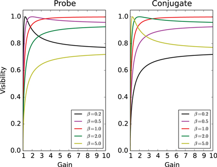
Figure 3. Visibility of two output fields as a function of G with different β. Left: probe beam, right: conjugate beam. Different color lines are:  (black),
  (magenta),
  (red),
  (green) and
  (yellow). As the gain increases, the visibility will saturate. When β is closer to the unit, the saturated visibility increases.
Download figure:
Standard image High-resolution imageThe interference phenomena can be explained as two individual phase insensitive FWM processes seeded only by the probe or conjugate beam interfering with each other. Each FWM process produces its own output of the probe and conjugate beams respectively. The two output probes of the same frequency overlap spatially under our current symmetric geometry and so are the two output conjugate beams. Thus these two output probe (conjugate) beams will interfere with each other, leading to the amplification or de-amplification of the beams. From this point of view, our two-mode PSA induces interference signals for each output port.
From the above discussion, we find that the probe beam could be amplified or de-amplified determined by the phase ϕ of the input beams. However, the probe beam always has increased noise after an amplification or de-amplification process. We will show the result by studying the noise level of probe beam. Usually, it is quantified by the ratio of the variance of the output after the PSA to the variance at the standard quantum limit (SQL), namely:

Here one can easily calculate the term  from equation (2), and
  is just the mean value of the output photon number, i.e.
  . The result corresponds to the linear increase of the noise on the probe beam as the gain increases. It is not dependent on the phase of the input beams whether or not the system is amplifying or de-amplifying the input signal. The second term on the right side of equation (2) represents the added noise induced by the amplifier [49]. This kind of additive noise is independent of the input probe mode. Therefore this kind of amplifier always introduces excess noise to the input signal. The same result can be obtained for the conjugate beam due to the symmetrical role of probe and conjugate beams in this system.
In conclusion, this system behaves as an amplifier whose gain is determined by the phase ϕ of the input beams. From the point of interference, it can be seen as an interferometer whose visibility depends on the intensity ratio β of the input beams.
3.2. Quantum variances of intensity difference and the sum between the output probe and conjugate beams
The degree of squeezing of the intensity difference between the probe and conjugate beams with respect to the SQL is given by:


When we seed a vacuum field to the conjugate port, i.e.  there is a quantum noise reduction of
  in intensity difference, which agrees with the result in [27]. The degree of squeezing depends not only on the gain G but also the ratio β and the phase ϕ as shown in figures 4 and 5. In figure 4, we set the phase of input beams ϕ as zero to study the influence of the intensity ratio β on the degree of intensity difference squeezing. As shown in figure 4, when the ratio β is above 1, the squeezing level decreases as β increases. It slowly approaches the squeezing level of the PIA configuration when β tends to infinity (not shown in the figure 4), which corresponds to the case of seeding a vacuum field to the conjugate port. As β decreases to zero, which means seeding a vacuum field to the probe port, the squeezing level also returns to the PIA configuration. We also find the maximal squeezing is achieved when
  , which corresponds to the maximal visibility for both the probe and conjugate beams as discussed in figure 3. Most importantly, nearly 3 dB enhancement (e.g. for G = 5, 2.98 dB is possible) on the squeezing level of intensity difference between the probe and conjugate beams can be achieved in this system compared to the PIA configuration with the same gain. As shown in figure 5, the squeezing level varies with the phase, here we set
  . When
  , this system produces relative intensity squeezing between the two output fields. In particular, when
  , the squeezing level is even lower than the PIA configuration with the same gain. When
  , we get anti-squeezing on the intensity difference between the two output fields. We could either enhance the squeezing level compared to the PIA configuration or get an anti-squeezing on intensity difference via varying the phase ϕ of the input beams. The maximal squeezing level on intensity difference is obtained when
  and
and  , which corresponds to the situation that two pump photons convert to one probe photon and one conjugate photon. The numbers of the generated photons on both beams are the same in principle, thus the noise of intensity difference is reduced in this case.
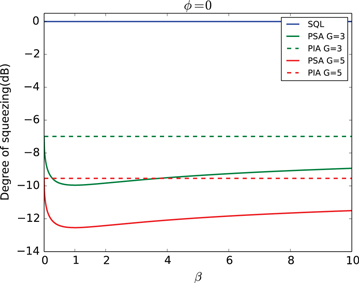
Figure 4. The squeezing level of intensity difference in decibels as a function of β when  . The squeezing level becomes maximal when
  and approaches the squeezing level in the PIA configuration as β tends to infinity or zero. Dashed lines: the squeezing level in the PIA configuration; solid lines: the squeezing level in the PSA configuration. Green lines: G = 3, red lines: G = 5, blue line: SQL.
Download figure:
Standard image High-resolution image
Figure 5. The squeezing level of intensity difference in decibels as a function of the phase ϕ when  . The squeezing level can be lower than that of the PIA when
  . Otherwise, when ϕ is close to π, the noise is even higher than SQL, thus it is anti-squeezing. Dashed line: the squeezing level in the PIA configuration, solid lines: the squeezing level in PSA configuration. Green lines: G = 3, red lines: G = 5, blue line: SQL.
Download figure:
Standard image High-resolution imageThe nearly 3 dB enhancement can be interpreted by the interference between the two individual phase insensitive FWM processes seeded only by the probe or conjugate beam. Here we assume both FWM processes are operating at the same gain of G. Considering the FWM process seeded only by the probe beam, the intensity of the output probe beam is  and the newly generated conjugate beam has an intensity of
  . The same results can be obtained for the FWM process seeded only by the conjugate beam. The intensity of the amplified conjugate beam is
  , and
, and  for the newly generated probe beam. For simplicity, we assume
  . Therefore, the maximal intensity of the probe beam of the PSA seeded by both the probe and conjugate beams is
  . When
  , this maximal intensity is approximately given by
  . Since the number difference operator
  is invariant during the FWM process, the maximal squeezing degree of the intensity difference will occur when two FWM processes exhibit constructive interference. Thus

The maximal squeezing degree of the intensity difference in decibels is approximately  . As mentioned above, the second term corresponds to the squeezing degree of the phase insensitive amplifier. In other words, the nearly 3 dB enhancement comes from the constructive interference of the two individual FWM processes.
The noise of the intensity sum between the probe and conjugate beams is always amplified and well above its corresponding SQL during the FWM process in the PIA configuration. Due to the interference phenomena on both the probe and conjugate beams, we find that the noise of the intensity sum of the two output fields could be well below the SQL within a very narrow phase and intensity ratio range in the PSA configuration.
From equations (2) and (3), the degree of squeezing of the intensity sum with respect to the SQL is given by:


where ![$\alpha =1/[(2G-1)+4\sqrt{G(G-1)}\frac{\sqrt{\beta }}{1+\beta }{\rm cos} \phi ]$](https://content.cld.iop.org/journals/1367-2630/17/2/023027/revision1/njp508330ieqn75.gif) . In the PIA configuration, the
. In the PIA configuration, the  is approximately
  independent of ϕ. Due to the term α in equation (15), when ϕ nears π, it is possible to obtain a squeezing level below the SQL. Additionally, the noise property depends on the ratio β. In figure 6, we set the phase of input beams ϕ as π and study how the intensity ratio β affects the degree of intensity sum squeezing. In figure 7, we set
  to study the influence of the phase on the degree of intensity sum squeezing. From these two figures it is clear that the squeezing level below the SQL can only be observed within a very narrow range of both β and ϕ. The size of the range depends on G. The higher the gain, the narrower the range. Moreover, a larger squeezing level can be achieved with higher gain G, e.g. for a given G = 5, more than 10 dB of squeezing is possible, shown as the red curves in figures 6 and 7. The maximal squeezing level is achieved when
  and
and  , which corresponds to the situation in which two input photons convert to two pump photons.
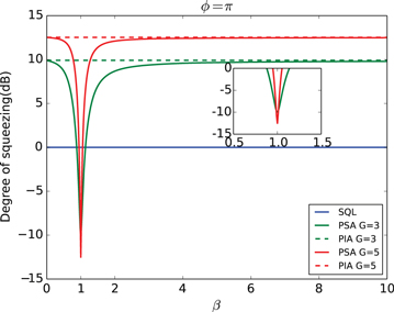
Figure 6. The squeezing level of intensity sum in decibels as a function of the ratio β when  . Dashed lines: the anti-squeezing level in the PIA configuration; solid lines: the squeezing level in the PSA configuration. Green lines: G = 3, red lines: G = 5, blue line: SQL. Inset: the expanded plot around
  .
.
Download figure:
Standard image High-resolution image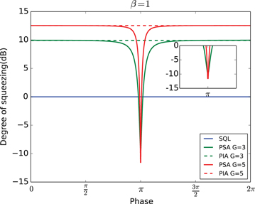
Figure 7. The squeezing level of intensity sum in decibels as a function of the phase ϕ when  . Dashed lines: the anti-squeezing level in the PIA configuration; solid lines: the squeezing level in the PSA configuration. Green lines: G = 3, red lines: G = 5, blue line: SQL. Inset: the expanded plot around
  .
.
Download figure:
Standard image High-resolution imageIn conclusion, in order to observe the squeezing for the intensity difference between probe and conjugate beams, the input signals should be amplified. Moreover nearly 3 dB of enhancement is theoretically predicted compared to the PIA configuration with the same gain. In contrast, the input signal should be de-amplified in order to observe the squeezing for the intensity sum. Additionally, this type of intensity sum squeezing can never be realized in the PIA configuration.
3.3. Quantum entanglement between the output probe and conjugate beams
The 'amplitude' and 'phase' quadrature operators of the field are defined by:

Based on the above discussion, it is better to have two input signals of equal power to show high non-classical properties of this system. Thus for the following calculations, we assume  .
.
From equation (16) the sum/difference combinations of the amplitude and phase quadratures of probe and conjugate are:


The variances for each combination are:


The amplitude quadratures sum and phase quadratures sum (amplitude quadratures difference and phase quadratures difference) between the probe and conjugate beams forms one pair of Heisenberg uncertainty conjugate variables, since ![$[{{\hat{X}}_{a}}+{{\hat{X}}_{b}},{{\hat{Y}}_{a}}+{{\hat{Y}}_{b}}]=2{\rm i}$](https://content.cld.iop.org/journals/1367-2630/17/2/023027/revision1/njp508330ieqn86.gif) (
(![$[{{\hat{X}}_{a}}-{{\hat{X}}_{b}},{{\hat{Y}}_{a}}-{{\hat{Y}}_{b}}]=2{\rm i}$](https://content.cld.iop.org/journals/1367-2630/17/2/023027/revision1/njp508330ieqn87.gif) ). But the amplitude quadratures sum and phase quadratures difference (amplitude quadratures difference and phase quadratures sum) are commutative since
). But the amplitude quadratures sum and phase quadratures difference (amplitude quadratures difference and phase quadratures sum) are commutative since ![$[{{\hat{X}}_{a}}+{{\hat{X}}_{b}},{{\hat{Y}}_{a}}-{{\hat{Y}}_{b}}]=0$](https://content.cld.iop.org/journals/1367-2630/17/2/023027/revision1/njp508330ieqn88.gif) (
(![$[{{\hat{X}}_{a}}-{{\hat{X}}_{b}},{{\hat{Y}}_{a}}+{{\hat{Y}}_{b}}]=0$](https://content.cld.iop.org/journals/1367-2630/17/2/023027/revision1/njp508330ieqn89.gif) ). In order to show entanglement, the noise reduction in the two generalized quadratures (
). In order to show entanglement, the noise reduction in the two generalized quadratures ( or
or  ) must fulfill the in-separability criterion:
  or
or  [50, 51].The value of E for our system is changing with the phase of the pump field, as shown in figure 8. The solid lines represent the amplitude quadratures difference and phase quadratures sum entanglement (denoted as type I entanglement) and the dash lines represent the amplitude quadratures sum and phase quadratures difference entanglement (denoted as type II entanglement). The strongest entanglement for type I is obtained when
  which corresponds to the maximal amplification for the input beams. On the other hand, the strongest entanglement for type II entanglement is achieved at
  which corresponds to the maximal de-amplification for the input beams. These two types of quadrature entanglement can be achieved by changing the phase θ. Both types of quadrature entanglement can only be observed within a phase range which is determined by the gain G. With higher gain, the value of E gets smaller meaning stronger entanglement, but the phase range for observing the entanglement becomes narrower. E.g. with a given G = 5, the smallest value of E is equal to 0.11. When
  , it shows type I entanglement. When
  , it shows type II entanglement. The size of phase ranges for observing these two types of quadrature entanglement are the same.

Figure 8. Upper graph: the value of E varies with the phase θ. Lower left: the expanded plot around  of solid line, right: the expanded plot around π of dash line. Solid lines: type I entanglement, dash lines: type II entanglement. Green lines: G = 3, red lines: G = 5 and blue lines: E = 2. Below the blue line means there exists quantum entanglement between the generalized quadratures.
Download figure:
Standard image High-resolution image
4. Conclusion
In this paper, we have studied an experimental scheme to build a two-mode PSA via a double-Λ FWM process in hot Rb atomic vapor. Two weak coherent fields, the probe and conjugate beams, are crossed with a strong pump beam in the atomic medium. Although a similar structure of two mode PSA has been studied both theoretically and experimentally in fiber amplifiers and also implemented in an SU(1,1) interferometer, we have shown some new and interesting results for quantum squeezing and entanglement. Particularly, intensity sum squeezing between the two output beams is predicted theoretically. Moreover, nearly 3 dB of enhancement in intensity difference squeezing can be obtained compared to the PIA configuration with the same gain. Finally, we have also studied possible entanglement between the two output beams. Two types of quadrature entanglement can be obtained and manipulated by the phase of the input beams. These findings may find applications in quantum metrology and quantum information processing, such as the phase sensitive generation of entangled images, through quantum squeezing and entanglement manipulation.
Acknowledgments
We would like to thank the referee for the valuable comments. JJ would like to thank Dr Xianli Zhang for useful discussion. This work was supported by the National Natural Science Foundation of China under grant numbers 91436211, 11374104, 10974057, 11234003, the SRFDP (20130076110011), the Program for Professor of Special Appointment (Eastern Scholar) at Shanghai Institutions of Higher Learning, the Program for New Century Excellent Talents in University (NCET-10-0383), the Shu Guang project supported by Shanghai Municipal Education Commission and Shanghai Education Development Foundation (11SG26), the Shanghai Pujiang Program under grant number 09PJ1404400, the Scientific Research Foundation of the Returned Overseas Chinese Scholars, State Education Ministry and the National Basic Research Program of China under grant number 2011CB921604.
Footnotes
- 2
The noise figure here is defined as the signal-to-noise-ratio (SNR) of the input signal divided by the SNR of the output signal.