

Abstract
High-performance superconducting joints are the key to achieving persistent-mode magnets. Herein, the superconducting joints between Ba1−xKxFe2As2 (BaK-122) superconducting tapes were prepared by a simple cold-pressing method, and the joint resistance of the iron-based superconducting joint was estimated by field-decay method for the first time. Via the scanning electron microscope (SEM), electron backscattered diffraction (EBSD), electron probe microanalysis (EPMA) and x-ray computed tomography (XCT) measurements, it is found that the joint sample CP80 shows fine performance. At 4.2 K and 10 T, a transport critical current Ic of 105 A for the joint sample CP80 was measured, and the critical current ratio (CCR = Ijoint c/Itape c) of the joint was 94.6%. On the other hand, the joints exhibit a pretty low joint resistance of 2.7 × 10⁻¹³ Ω in self-field at 4.2 K. Among iron-based superconductors, we are the first to estimate the accurate resistance of iron-based superconducting joint by the field-decay method. All these show the great prospective to apply BaK-122 in a series of practical applications that require superconducting joints as key components.
Export citation and abstract BibTeX RIS
1. Introduction
The K doped '122' type (AeFe2As2, Ae = alkaline or alkaline earth elements) iron-based superconductors (IBSs) have been considered as one of the high-temperature superconducting materials that can be used to fabricate high-field magnets, due to their high superconducting transition temperatures (Tc) up to 38 K [1], very high upper critical field (Hc2) above 100 T [2, 3], small anisotropy with γ = Hc2 || ab/Hc2 || c of about 1.5–2 and large critical current density (Jc) over 106 A cm−2 in thin film [4–7]. Numerous studies have been reported to improve the critical current density of this superconductor and optimize the manufacturing process of superconducting tape [8–12]. For instance, the critical current density of short sample BaK-122 tapes can reach 1.5 × 10⁵ A cm−2 at 10 T and 4.2 K, and still maintains 105 A cm−2 at 14 T and 4.2 K in short sample [13], and first 100 m class IBS tapes were successfully prepared in 2016 [14]. All these excellent properties of IBSs indicate its application prospects in high-field magnets.
However, high-performance superconducting joints will be the key point to employ IBSs in future magnetic resonance imaging (MRI) machines. An MRI machine needs its magnet to generate a stable magnetic field during operation, which requires the decay rate of the magnetic field to be less than 0.1 ppm h−1 [15]. Furthermore, the first iron-based superconducting joint was successfully prepared in 2018 [16]. Nonetheless, they optimized the preparation process of superconducting joints by studying the thermogravimetricanalysis (TG) and differential thermal analysis (DTA) curve of SrK-122 IBS, and then the critical current ratio (CCR) of the SrK-122 superconducting joint was rising to 63% by prolonging the holding time and reducing the pressure during hot-pressing (HP) [17]. Imai et al prepared BaK-122 superconducting joints by cold-pressing (CP) process, and the CCR of the superconducting joint was about 90% [18]. On the other hand, the electron probe microanalysis (EPMA) mapping reveals that Ba and O are rich (K, Fe, and As are poor) along the joint interface, and still they have not measured the accurate resistance of the superconducting joints [16–18].
In this paper, we developed prepared BaK-122 superconducting joints via a simple CP method, compared with HP method, this method is more suitable for practical applications. The problem of inhomogeneities along the joint interface is solved, and the macro-cracks in the joint region are well controlled. The critical current of the best-performing joint sample was 105 A at 4.2 K and 10 T. The resistance of the iron-based superconducting joint was obtained by the field-decay measurement for the first time, and the resistance of the joint was 2.7 × 10⁻¹³ Ω in self-field at 4.2 K.
2. Experimental details
The BaK-122 tapes were prepared by the ex situ powder-in tube method. The initial materials for synthesizing Ba1−x Kx Fe2As2 precursors are Ba filings, K pieces, Fe and As powders. After fully mixing under the protection of argon atmosphere, the mixed powder was compacted and loaded into a metal tube. Then, the tubes were sintered at 900 °C for about 35 h. After adding tin powder, the sintered precursor was ground to powder with a mortar in an argon atmosphere. Then, a silver tube was used to pack the ground powder. After a series of cold working treatments, these silver tubes were processed into tapes of thickness 0.4 mm. Finally, the tapes were cut into short samples of suitable size, and then sintered under vacuum or argon atmosphere at 880 °C for about an hour.
Figure 1 shows the schematic of BaK-122 joints. First, as shown in figure 1(a), the silver sheath was ground off by sand paper until the superconducting core inside the tape was exposed to prepare a superconducting window. Subsequently, we align the two superconducting windows and wrap them in silver foil. Then, to make more close contact of the two superconducting cores, uniaxial pressure was applied, shown in figure 1(c). Table 1 summarizes the details of joint samples prepared at different pressures. Eventually, the prepared joints were sintered in argon atmosphere at 880 °C for half an hour.
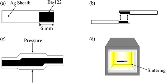
Figure 1. Schematic diagram of the preparation process of Ba-122 CP joints. (a) Peeling off the sheath metal. (b) Docking superconducting window. (c) Wrapping in Ag foil and CP. (d) Sintering.
Download figure:
Standard image High-resolution imageTable 1. Details of joint samples prepared at different pressures.
| Joint name | CP15 | CP20 | CP25 | CP30 | CP35 | CP40 | CP50 | CP60 | CP70 | CP80 |
|---|---|---|---|---|---|---|---|---|---|---|
| Pressure (GPa) | 0.69 | 0.92 | 1.15 | 1.38 | 1.61 | 1.84 | 2.3 | 2.76 | 3.22 | 3.68 |
In order to accurately measure the resistance of superconducting joints, a field-decay measurement was developed. Figure 2 shows the field-decay measurement device. To record the change of magnetic field in the experiment, a Hall sensor with 0.1 Gs sensitivity was installed at a suitable position. The temperature sensor was also installed on the top of the joint to measure the temperature of the field-decay test. Following the fabrication steps illustrated in figure 1, in order to form a closed-loop circuit, a BaK-122 superconducting joint was made between the two ends of the coil, as shown in figure 2(b). Then the whole closed-loop including the skeleton was heat treated at 880 °C for half an hour in an argon atmosphere. In the field-decay measurement, the background field was excited when the closed-loop coil was not superconducting. Subsequently, we made the closed-loop superconducting, and the background field was slowly reduced to zero.
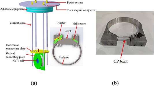
Figure 2. (a) Field-decay measurement setup. (b) Ba-122 closed-loop coil.
Download figure:
Standard image High-resolution imageThe critical current Ic of the joint samples were measured at 4.2 K using a standard four-lead method and evaluated by a criterion of 1 μV cm–1 at the Institute of Plasma Physics, CAS in Hefei. The crack distribution in the connection area of the joint sample was analyzed by the x-ray computed tomography (XCT, model: GE Microme|x). The microstructure and element distribution of the joint area were observed by EPMA (model: JEOL JXA8230). The filament grain structure was performed in a SEM (JXA-ISP100, JEOL) with an EBSD plugin (DIGIVIEW 5, EDAX).
3. Results and discussion
3.1. Transport properties of the superconducting joints
In order to investigate the superconducting current transmission performance of the jointed BaK-122 tape, firstly, the Ic characteristics of the joint were performed as is shown in figure 3. The data shown in figure 3(a) present the transport properties of BaK-122 superconducting joints at 4.2 K and magnetic fields from 4 to 14 T. The Ijoint c and Itape c curve shows a weak magnetic field dependence, which means that the superconducting joints prepared by this method are favorable for high field applications.
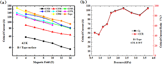
Figure 3. (a) Magnetic field dependence of transport critical current at 4.2 K for joints and tapes. (b) Critical current and CCR versus pressure curve.
Download figure:
Standard image High-resolution imageThe critical current and the CCR at 10 T and 4.2 K of the joint samples with different pressures are shown in figure 3(b). As shown in the figure, the CCR increases monotonically with the increase in the applied pressure from 0.69 to 2.3 GPa, and then the CCR is almost the same at 4.2 K and 10 T when further pressure increases to 3.68 GPa. The best BaK-122 joint sample CP80 shows a fairly high critical current of 105 A at 4.2 K and 10 T, and the CCR is 94.6%, which is the highest value ever reported so far for BaK-122 superconducting joints.
3.2. Microstructure of the superconducting joints
To further find out the reason for high CCR value of our CP joint, we investigated the microstructure from the longitudinal cross sections of BaK-122 superconducting joints by SEM characterization, as shown in figure 4. Figures 4(a)–(f) gives the longitudinal cross sections of BaK-122 superconducting joints pressed at 0.69, 1.38, 1.84, 2.3, 3.22 and 3.68 GPa, respectively. In figure 4(a), we can see that there are many holes and micro-cracks in the connection area. In figures 4(b)–(d), due to the increase in pressure, the number of holes and micro-cracks around the connection area was significantly reduced, which indicates that the connectivity of the joint had been improved. According to figures 4(d)–(f), it is obvious that the holes and micro-cracks were effectively eliminated, and at the same time the high-density microstructure can be observed. Thus, it is clear that the microstructure of BaK-122 joint is in line with their superconducting properties.
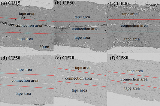
Figure 4. SEM image of longitudinal section of Ba-122 superconducting joint.
Download figure:
Standard image High-resolution imageThe study of the transport properties of superconducting twin films shows that IBSs have the problem of weak grain boundary connection similar to copper oxide superconductors [19]. Although the former has less stringent requirements on grain boundary angle than the latter, the texture of superconducting core is still the key to realize the high transmission performance of IBSs. Figure 5 shows the EBSD characterization results of the connection area of joint CP80, and the observation surface is the longitudinal section of the joint. Figure 5(a) gives the inverse pole figure (IPF) maps of joint sample CP80. We can find that the main colors of the connection area are green and blue, which shows significant orientation. This indicates that there is an obvious c-axis texture in the superconducting phase in the connection area, which is beneficial to the transmission of superconducting current. However, figure 5(b) shows that there are mainly small grains in the connection area, which also means that the grains in the connection area have not fully grown. According to this, the performance of the CP joint might be further improved by reducing the number of small-size grains in the connection area.
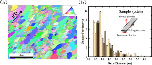
Figure 5. Grain orientation analysis of joint CP80 in rolling direction (RD). (a) IPF map of joint CP80. (b) Number fraction of grains as a function of grain diameter for joint CP80.
Download figure:
Standard image High-resolution imageAccording to our previous conclusions by scanning electron microscopy and electron probe microanalysis, the micro-cracks and potassium loss in the connection area will degrade the CCR performance of the joint [16, 17]. We analyzed the effect of the cold pressing process on element distribution in the joint region by SEM/EPMA image. The SEM image of the connection area of the joint sample CP80 is shown in figure 6. The results showed that the connection area healed well, and the joint interface is almost invisible. However, EPMA images reveal that there is almost no element loss along the joint interface. Therefore, all these show that the microstructure in the connection area of the joint prepared by CP can reach the same level as that of the joint prepared by HP.
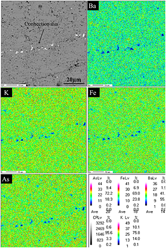
Figure 6. SEM and EPMA mapping image of the joint CP80.
Download figure:
Standard image High-resolution image3.3. Macrostructure of the superconducting joints
Figure 7 shows the XCT images of joints prepared by HP method and CP method. XCT images of joint samples taken from a top view. As shown in the picture, there are many macro-cracks in the joint region of the HP joint sample, while there are almost no macro-cracks in the joint region of the cold-pressed joint sample. Previous researches have shown that macro-cracks in the joint have a great influence on the transmission of superconducting current, and macro-cracks were almost unavoidable [16, 17]. In our opinion, the silver is very soft at high temperature, during hot pressing the silver will bite into the crack of BaK-122 superconducting core, which will enlarge the crack in the joint connection region. To solve this problem, we replace the HP method by CP method. Obviously, the macro-crack has been well controlled, and the result is in line with our expectations.
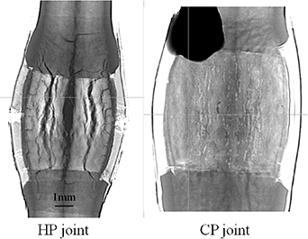
Figure 7. XCT images of the HP joint and CP joint.
Download figure:
Standard image High-resolution image3.4. Characterization of the superconducting joints with the field decay method
Finally, to characterize the performance of the superconducting joint in the persistent mode, the field-decay method was carried out. This method is very suitable for estimating resistance of superconducting joint below 10−9 Ω. The decay behavior normally has two stages as shown in figure 8. The current decays rapidly in the first stage, which is caused by the low n-value of the sample or the high induced current. Exponential resistance and joint resistance act simultaneously at this stage. In second stage, the decay of magnetic field is quite slow, and at this stage, the decay of magnetic field mainly depends on the joint resistance of superconducting joint [20, 21].
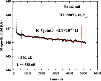
Figure 8. Time decay curve of the captured magnetic (y-axis field is the induced field in the closed-loop coil).
Download figure:
Standard image High-resolution imageA specific temperature and magnetic field is required for the whole field-decay measurement period, which is 4.2 K and self-field. Before estimating the resistance, the magnetic field was stabilized for about 1000 s, and the time after this process is recorded as the initial time t0, and the magnetic field corresponding to the initial time t0 is B0. Estimation of joint resistance from time decay of magnetic field in L–R circuit time constant:
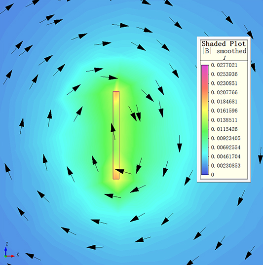
where B is the field at time t, B0 is the magnetic field at time t0, L is the inductance of the closed-loop coil. The estimated joint resistance according to the L–R circuit decay equation was 2.7 × 10⁻¹³ Ω at 4.2 K and 0 T. The persistent current can be estimated by the Hall sensor. The persistent current can be estimated by the Hall sensor. The self-field at the Hall sensor generated by the closed-loop coil was simulated as shown in figure 9. The relationship between them is 110 Gs per 100 A. Thus, the persistent current corresponding to 145 Gs is 131.8 A in the test. The test results of the joint resistance meet the application requirements of the joints in MRI and nuclear magnetic resonance (NMR) magnets. For the practical applications of IBSs in the future, this is very exciting news.
Figure 9. The self-field generated by the closed-loop coil with the persistent current of 100 A.
Download figure:
Standard image High-resolution image
As the results shown above, the superconductivity of BaK-122 superconducting joints can be significantly improved by CP. Firstly, in this work, the problem of inhomogeneous distribution of elements along the joint interface has been well controlled. It is known that the element loss along the joint interface tends to happen during the fabrication of superconducting joint, which will lead to a wide superconducting transition temperature Tc [16, 18]. Secondly, SEM characterization of the joint connection area indicates that the micro-cracks and holes along the joint interface could be controlled by increasing the pressure during the CP process. It is known that micro-cracks can block the transmission of current at the joint interface. This is harmful to the transmission performance of superconducting joints. Most importantly, there are almost no macro-cracks in the joint region compared to the HP joint. Macro-cracks were almost unavoidable in the joint sample prepared by HP. This may be one of the key points for the CP process to prepare high-performance superconducting joints. However, in this case, we find that there are many small grains in the connection area, which means that the grains in the connection area have not fully grown. For future research, further increase in the superconductivity for the BaK-122 superconducting joint is expected by optimizing the heat treatment parameters to make the grains in the connection area fully grown.
4. Conclusions
To summarize, we prepared the superconducting joints of IBS by the CP method, and estimated the iron-based superconducting joint resistance by field-decay method for the first time. Surprisingly, the current carrying capacity of the joint is almost the same as that of the original tape from 4 to 14 T at 4.2 K. At the same time, the resistance of the joint also reaches 2.7 × 10⁻¹³ Ω in self-field at 4.2 K. Our microstructure SEM, EPMA and EBSD examination revealed a very small crack, little potassium loss and obvious c-axis texture in the joint cross-section area. The macrostructure XCT examination revealed there are almost no macro-cracks in the joint cross-section area. Undoubtedly, this is very exciting news for the practical applications of BaK-122 IBS in the future.
Acknowledgments
This work is partially supported by the National Key R&D Program of China (Grant Nos. 2018YFA0704200 and 2017YFE0129500), the National Natural Science Foundation of China (Grant Nos. 51861135311, U1832213 and 51721005), the Strategic Priority Research Program of Chinese Academy of Sciences (Grant No. XDB25000000), Key Research Program of Frontier Sciences of Chinese Academy of Sciences (QYZDJ-SSW-JSC026), the International Partnership Program of Chinese Academy of Sciences (Grant No. 182111KYSB20160014).
Data availability statement
All data that support the findings of this study are included within the article (and any supplementary files).