

Abstract
Both the pancake coiling and conductor on round core (CORC) cabling processes consist of winding second-generation high-temperature superconducting tape (REBCO) in a core. The contact behavior between the tape and the core during the winding process directly affects the critical current, cable flexibility, mechanical support and electrical contact resistance. Therefore, the winding process needs to be optimized to produce pancake coils and CORC cables with the desired electrical and mechanical properties. This paper comprehensively considers the role of the relaxation and Poisson effects. The theoretical model and the finite element model (FEM) for calculating the contact stress during the winding process are established, and a formula for the estimation of the contact force is proposed. The suitable winding pre-tension force, winding curvature radius of SCS2030 (2 mm width and 30  m substrate thickness) and SCS4050 (4 mm width and 50
  m substrate thickness) of REBCO tapes are obtained and discussed by accounting for the relaxation effect and the critical current degradation limit. With consideration of the Poisson effect, the nonlinear contact behavior is investigated. In addition, the relaxation effect, Poisson effect and plasticity of the REBCO tape are taken into account in the FEM model. The results show that the axial strain in the REBCO layer during the winding process is related to the contact behavior. The greater the winding pre-tension force, the smaller the helical curvature radius, and the greater the contact force. The distribution of contact stress for several winding factors (winding pre-tension force, winding angle and the core radius) is divided into three contact types: the single-line contact, the double-line contact and the surface contact. The FEM model results are consistent with the theoretical evaluation and are more suitable for practical winding cases. This research is the basis for designing and optimizing pancake coils and CORC cables.
Export citation and abstract BibTeX RIS
1. Introduction
Winding is a natural method and a traditional manufacturing process in which tape or rope is wound around a core. The winding of the material improves its overall mechanical performance and enhances other features. Hemp ropes, yarns, composite shells, DNA helix structures, and power transmission cables are all winding examples [1]. Over the past decade, with the growing maturity of high-temperature superconducting (HTS) technology, cables and coils made of RE-Ba2Cu3O7−δ (REBCO) tapes may soon be widely used in future applications like nuclear magnetic resonance (MRI), accelerator magnets, controlled fusion reactors, etc [2]. The internal structure of the considered REBCO tape, the principal layouts of a pancake coil [3] and conductor on round core (CORC) cable [4, 5] are shown in figure 1.

Figure 1. (a) SuperPower Inc. SCS4050 REBCO tape. (b) HTS pancake coils. (c) CORC cable. (Here,  is the radius of helical curvature.)
Download figure:
Standard image High-resolution imageTo produce CORC cables and layer-wound coils, the REBCO tapes are helically wound around a central core with 30–50° (CORC cables), 0–10° (layer-wound coils) and 0° (pancake coils), respectively. However, the REBCO tapes are strain-sensitive, and excessive deformation will result in the degradation of critical superconducting properties and electromagnetic performance [6]. During the winding process, the tape's deformation is affected remarkably by the contact with the core. The mechanical properties of pancake coils and CORC cables are related to the initial contact during winding [7, 8]. The interlayer contact resistance is also a critical electrical property, which determines the ability of current sharing [9–12], the generation of AC loss [12, 13] and the quench protection method [14, 15]. Therefore, it is essential to study the contact behavior during the winding process. However, the winding is a rather complex deformation process [16–19]. The actual contact is indeed strongly nonlinear, which leads to difficulties in solving this problem.
Research on the mechanical behavior of the winding process dates back to 1950; Gashwell et al conducted a theoretical analysis of the thin rectangular plate during the pure bending deformation process [20]. They revealed the anticlastic shape (the tape edge lifting; see figure 2(a)) mode of the plate due to the Poisson effect (longitudinal stress produces transverse deformation) and provided detailed calculations for thin plates with different bending curvature, size and stiffness. In 1955, Fung et al further investigated the pure bending deformation of a thin rectangular plate and calculated the edge lifting height when the anticlastic deformation occurred [21]. The winding process involves bending deformation following the anticlastic shape and a complex macro contact interface interaction between the tape and the core (see figure 2). In 1972, Meier et al described this contact interface and calculated the shape under different pre-tension loads and different winding radii [22]. Another study was performed in 1981; Wang et al simplified the winding process to a plane strain problem and analyzed the force on the elastic tape [23]. They indicated that the pre-tension force line could not be tangent to the central core when winding stiff tape, referred to as the relaxation effect. In 1998, Benson made a detailed calculation for the relaxation phenomenon [24]. To our knowledge, so far, no one has reported detailed contact behavior during the helical winding of the CORC structure.

Figure 2. (a) The phenomenon of anticlastic shape due to the Poisson effect. (b) The relaxation effect during the winding process.
Download figure:
Standard image High-resolution imageCORC cables are commercialized by Advanced Conductor Technologies LLC (www.advancedconductor.com), although the application of CORC would highly benefit from further optimizations. The first optimization is related to the critical current degradation caused by the cabling process. In 2015, Van der Laan et al measured the critical current degradation of REBCO tapes with various winding radii and different tapes [25]. Zhu et al proposed a calculation method for the radius of the helical curvature, which allows estimation of the strain in the REBCO layer during the CORC cabling [26]. Wang et al simulated the cabling process of CORC and calculated the strain distribution [19]. The second optimization concerns bending flexibility, exploring the minimum bending radius for magnets made with CORC cables. In 2018, Anvar et al studied the bending process of CORC cables through finite element model (FEM) simulations. They indicated that the bending flexibility of CORC cables is strongly related to the coefficient of friction between the tapes [27]. The third important optimization is treating the need for mechanical support. Mulder et al designed a cable in conduit conductor made of six CORC cables and measured its electrical properties [28]. Van der Laan et al applied a cyclic transverse load to a CORC cable in operation [29]. Their results show that the mechanical support method of the CORC cable is essential and needs to be optimized. Finally, the electrical contact resistance between the layers needs to be optimized. Lu et al measured the contact resistance between two REBCO tapes under load [30]. Gao et al introduced the interface similarity index to calculate the contact resistance [31], and they also investigated the copper to copper contact surface under cyclic load and variable temperature [32]. Yagotintsev et al pointed out that the contact resistance controls the coupling loss in an alternating magnetic field and the current sharing [12]. In addition, the latest experiment by Kujovič et al exposed the micron-level lifting at the tape edges as being like an 'ear' shape during the bending process due to the Poisson effect [33, 34]. This 'ear' lifting makes the contact behavior very complicated, and also directly affects the critical current ( ) degradation, cable flexibility, mechanical support capacity and contact resistance, which will endanger magnet operation safety. However, this nonlinear contact behavior caused by the Poisson effect has not received much attention so far in previous studies. Therefore, a detailed analysis of the contact behavior during the winding process is the key to solving the above problems.
In this paper, a two-dimensional (2D) simplified winding model of a pancake coil is established through theoretical methods, considering the two main factors in the winding process: relaxation and Poisson effect. As a result, the contact behavior between the tape and the core is obtained. Then, the CORC three-dimensional (3D) helical winding model is established by a COMSOL® model. After describing the pancake coiling and the CORC cabling processes, the contact stress distribution was calculated. The FEM results were then compared with the theoretical results and verified by experimental winding tests. The theoretical model and the FEM are described in the second and third sections, respectively. The fourth section contains the results and discussion. Finally, the conclusion is presented.
2. Theoretical model description
2.1. Relaxation effect (2D simplified coil winding model)
The REBCO tapes have a width of 2 mm (SCS2030) and 4 mm (SCS4050), which is much larger than their thickness of 45 μm (SCS2030) and 96 μm (SCS4050). As such, the simplified 2D model for the winding process of the pancake coils, as shown in figure 3, is based on the following assumptions and approximations with all parameters used in the equations listed in table 1:
- (a)The dynamic factor in the winding process is ignored, assuming a quasi-static process.
- (b)The width is considered to be much larger than the thickness, assuming that
 , which is the plane strain hypothesis.
 - (c)It is assumed that the multi-layered composite REBCO tape is a homogeneous material, the mechanical parameters are calculated by the volume fraction of each material component, which is the homogenization hypothesis, and only validating the XY plane.
- (d)The friction during the winding process is ignored.
- (e)The end effect of the REBCO tape and the center roller effect are not taken into account, according to the Saint–Venant principle. (The meaning of the Saint–Venant principle is that the difference between the effects of two different but statically equivalent loads becomes very small at sufficiently large distances from loads.)
- (f)It is assumed that the central core is rigid.
- (g)The distance between the reel and the core is considered very long,.


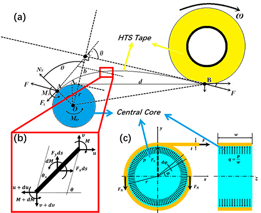
Figure 3. The schematic diagram of the winding process for coiling with definition of parameters. (a) Is the overall model; (b) is the detail of the tape; (c) is a model to calculate the relationship between the radial contact force and the circumferential axial force.
Download figure:
Standard image High-resolution imageTable 1. List of parameters.
| Parameter | Description | Parameter | Description |
|---|---|---|---|

| Winding pre-tension force |

| Tape thickness |

| Normalized 
|

| Tape width |

|

|

| Characteristic length |
| r | Core radius |

| Tape length |

| Curvature radius |

| Poisson ratio |

| Applied moment |

| Bending deflection |

| Relaxation angle |

| Helix pitch |

| Relaxation offset distance |

| Winding helix angle |

| Distance between reel and core 
|

| Winding factor ![$\sqrt[4]{{\frac{{3\left( {1 - {\nu ^2}} \right)}}{{{\rho ^2}{t^2}}}}}$](https://content.cld.iop.org/journals/0953-2048/34/7/075003/revision3/sustabf710ieqn27.gif)
|

| Normal contact force |

| Normalized 
|

| Average normal contact force |

| Tape stiffness 
|

| Tangential friction force |

| Young's modulus |

| Uniform contact load |

| Moment of inertia |

|

|

|
![$\eta = w\sqrt[4]{{\frac{{3\left( {1 - {\nu ^2}} \right)}}{{{t^2}}}}}$](https://content.cld.iop.org/journals/0953-2048/34/7/075003/revision3/sustabf710ieqn41.gif)
|
Based on the above assumptions, considering isotropic stiffness of the tape for winding, the position where the tape starts to contact the core is in reality at point  , and not at point
  due to the relaxation effect. This phenomenon always exists in a natural winding process [23]. The relaxation offset distance is defined as the distance at which the pre-tension force extension line is tangent to the core, and the relaxation angle is defined as
  in figure 3(a). For the force analysis from figure 3, the following can be posed:


2.2. Poisson effect and anticlastic curvature (3D coil winding model)
In this section, assumption 2 from section 2.1 on the plane strain hypothesis is further elaborated by discussing the influence of the tape width on the winding result in detail. The cabling and coiling process can be described by the general equation of the cylindrical shell proposed by Timoshenko [16]; see figure 4.
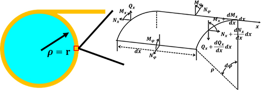
Figure 4. Force analysis of the differential element after winding.
Download figure:
Standard image High-resolution imageDue to symmetry, three of the six force equilibrium equations are automatically satisfied. Then, the following can be derived:


This equation is a linear elastic equation and does not consider material plasticity.
Equation (15) is a fourth-order non-homogenous differential equation with a general solution:

Here,  and
and  are undetermined constants determined by boundary conditions, and
  is a particular solution, which depends upon the form of applied loading
  . When
  is zero, there is no contact between the tape and the core, which represents a pure bending process. Then, the solution of equation (15) is:

with
Due to the symmetry in the width direction of the tape and  , the approximate simplified form of equation (17) can be obtained as [20]:

Figure 5 shows the deflection diagram of the half-width plate after pure bending for different core radii. It presents the obviously anticlastic shape mode of tapes subjected to pure bending.
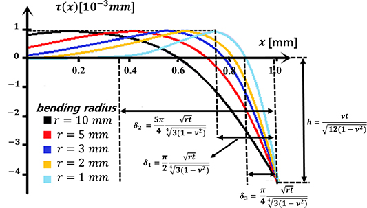
Figure 5. Deflection diagram of the half width plate under pure bending.
Download figure:
Standard image High-resolution imageBased on equation (18), we also get the 'ear' lifting length (distance from the edge to the point of maximum contact force) of the tape as:
and the 'ear' lifting height (height at which the edge is lifted) is:
When  is a non-zero constant, three contact shapes can be obtained according to [22], as shown in figure 6.
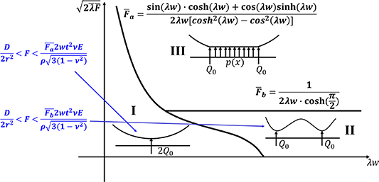
Figure 6. Diagram of different contact shapes under a variety of pre-tension forces and several other winding factors.
Download figure:
Standard image High-resolution imageEquations (22) and (23) give the expressions of  and
and  , which are two critical normalized values when the winding factor
  and tape width
  change. The contact type I is the single-line contact, the contact type II is the double-line contact, and the contact type III is the surface contact

The horizontal axis in figure 6 is basically the tape width divided by the tape thickness and the radius of curvature. The vertical axis is basically the pre-tension force multiplied by the radius of curvature and divided by the thickness of the tape. Therefore, the larger the radius of curvature, the contact shape is either type I (at low tension) or type III (at high tension). Otherwise, the contact shape is either type II (at low tension) or type III (at high tension).
It is worth noting that this method is an approximate solution, which approaches the contact force as a combination of the concentrated and uniform load. For the real case, the contact force distribution  is a function of the deflection
  . Then, equation (15) has strong nonlinear characteristics and it is difficult to achieve an analytical solution. Therefore, a FEM method is required. In the next section, the contact force distribution is given by the finite element method.
2.3. Helical winding (3D CORC winding model)
The CORC cabling process goes with a specific helix angle as defined in figure 7.
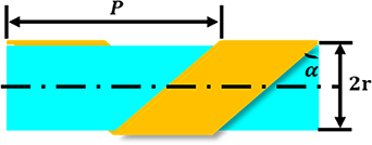
Figure 7. Diagram of CORC helical structure with definition of the winding angle.
Download figure:
Standard image High-resolution imageTherefore, the core radius r from above in the CORC cabling process will be replaced with a helical curvature radius ρ:


The description of the CORC cabling process also contains the relaxation and Poisson effects. After replacing r with  , equations (26) and (19) can approximately describe the relaxation, the contact force and the 'ear' lifting length during the CORC cabling process. The exact distribution can then be obtained from the FEM.
3. FEM model description
The FEM is established following a schematic diagram embedded in COMSOL® software. The model contains two defined main regions: the core and the REBCO tape. The core is the rigid domain, and the tape is the solution domain. One end of the tape is fixed to the core's surface, and the other end is given a pre-tension force Fpre. The rigid core is designated to rotate, with the boundary conditions, as shown in figure 8.
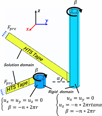
Figure 8. Pancake coil and CORC cable-winding model with boundary conditions.
Download figure:
Standard image High-resolution imageThe contact boundary conditions between the tape and the core are subjected to the penalty function method. The tape is considered as a homogeneous material and the ideal elastoplastic constitutive relation is used [6, 19]. All the parameters in the FEM model are listed in table 2.
Table 2. Parameters used for the FEM model [6].
| Parameter | Value |
|---|---|
| Young's modulus of SCS4050 tape (300 K) | 130 GPa |
| Young's modulus of SCS2030 tape (300 K) | 150 GPa |
| Poisson ratio tape | 0.3 |
| Plastic yield stress of SCS4050 tape (300 K) | 610 MPa |
| Plastic yield stress of SCS2030 tape (300 K) | 750 MPa |
Friction factor 
| 0.1 |
4. Results and discussion
4.1. Pancake coil winding
First, the winding process of a pancake coil is simulated. Therefore, the SCS4050 tape is taken as an example, the pre-tension force is set to 50 MPa, the core radius is taken to be 3 mm and the time is 10 s. The result, shown in figure 9, depicts that the contact force between the tape and the core is uniformly along the tape length, symmetrically along the tape width and without contact force on the tape edge. This happens to be the contact type III shown in figure 6. The yellow dashed line indicates where the relaxation area ends. The red dashed line position indicates the area with stress concentration, at which the tape and the core start to make contact. The relaxation effect remains stable during the entire calculation time.

Figure 9. The process of the pancake coiling. (r = 3 mm, T = 50 MPa, 2w = 4 mm, t = 0.096 mm, α = 0°).
Download figure:
Standard image High-resolution imageAs shown in figure 10, a test platform is prepared to verify the theoretical and FEM simulations. Figure 10(d) shows how to measure the relaxation offset distance b and the relaxation angle  ; a micrometer and a protractor are used in this step. Figure 11 compares the relaxation offset angle and relaxation offset distance under different winding pre-tension forces through theoretical calculations, FEM simulations and experimental tests. The tapes were prepared from SCS4050 by SuperPower Inc. The experimental test is performed by hanging different weights (50, 100, 200, 300, 500, 700, 900, 1000, 1500, 2000, 2500, 3000 and 4000 g) acting as the winding pre-tension force, and then slowly rotating the aluminum roller (
 mm). The measured results show that as the winding pre-tension force increases, the relaxation effect becomes weaker. The results obtained from the theoretical calculations, FEM simulations and winding tests are consistent. However, the FEM model is smaller than the theoretical calculation results and closer to the test data because of the plasticity.
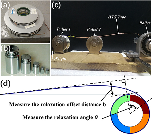
Figure 10. (a) The REBCO tapes produced by SuperPower Inc. (b) The weight. (c) Relaxation effect test. (d) Schematic diagram of measurement method.
Download figure:
Standard image High-resolution image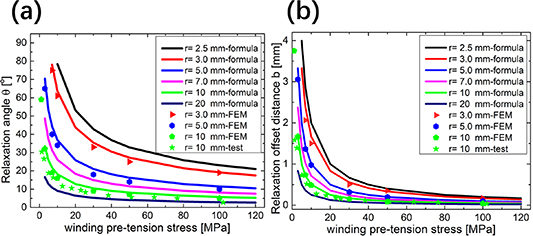
Figure 11. (a) Relaxation angle  . (b) Relaxation offset distance
  ; the solid line is calculated by equations (6) and (7), and the dot diagrams are the finite element results under three winding radii (r = 3, 5 and 10 mm) and test results (r = 10 mm).
Download figure:
Standard image High-resolution imageThe next step is to calculate the contact behavior between the tape and the core with the FEM model. Figure 12 shows the contact stress distribution during the coiling process for two core radii. When the winding pre-tension force is small, the relaxation effect is more pronounced. For a winding pre-tension force less than  , the winding fails (see figure 12(a), when T = 5 MPa, the tape is buckling). Detailed results are gathered in figure 13, showing that the contact force is highest at position δ from the edge of the tape and decreases rapidly to zero at the edge of the tape. This distribution indicates that the tape produces an anticlastic shape due to the Poisson effect during the winding process. According to equation (19), the 'ear' lifting occurs at the position
  from the tape edge, where the tape first contacts the core during winding. Finally, after the winding is completed, the contact force at this position is the largest. Interestingly, the 'ear' lifting length
  is only related to the winding factor
  and not to the pre-tension force
  and tape width
  . Following the FEM, with results presented in figure 13, also leads to a similar outcome. Using equation (21) the lifting height
  at the edge of the tape is calculated and obviously this part of the tape has no contact with the core during winding and the contact force is zero. Using equation (11), we can approximate the average contact force between the tape and the core, as shown by the dashed lines in figure 13. The contact force is inversely proportional to the radius and directly proportional to the winding pre-tension force. When the winding pre-tension force gradually increases, the contact type changes from double-line contact (contact type II) to single-line contact (contact type I), as shown by the solid lines in figure 13(a). When the core radius gradually increases, the contact type is type III and never changes, but the contact force value is averaging progressively.
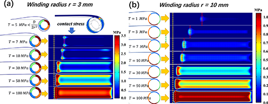
Figure 12. The contact stress distribution during coiling process for different winding pre-tension forces, (r = 3 and 10 mm, 2w = 4 mm, t = 0.096 mm, α = 0°).
Download figure:
Standard image High-resolution image
Figure 13. (a) The contact stress distribution after winding with different winding pre-tension forces (r = 3 mm, 2w = 4 mm, t = 0.096 mm, α = 0°). (b) The contact stress distribution after winding with different core radii (T = 50 MPa, 2w = 4 mm, t = 0.096 mm, α = 0°).
Download figure:
Standard image High-resolution image4.2. CORC cabling process
For the helical winding used for CORC cabling, the SCS4050 tape is taken as an example. The pre-tension force is 100 MPa, the helix angle is 45°, the core radius is 3 mm and the time is 10 s. The result is shown in figure 14, with the yellow dashed line marking the relaxation area. The red dashed line is the position at which the tape and the core start to make contact. The results show that the helical winding is different from the pancake coiling. During the helical winding process, the relaxation on both sides of the tape is different, while symmetrical for the pancake winding process. For further explanation, the non-relaxation side is referred to as the A-side and the relaxation side as the B-side. Dividing the whole helical wound tape into two sections, the forward helix is the first half of the wound tape length, and the backward helix is the rear half. In the forward helix, the A-side's contact force is greater than that of the B-side, and in the backward helix, the A-side's contact force is less than that of the B-side. The relaxation on both sides of the tape is different during helical winding, which causes the contact force between the tape and the core to be asymmetric in the width direction. In addition, no contact force on the tape edge indicates that the edge 'ear' lifting exists during the helical winding, affecting the distribution of the axial strain in the REBCO layer. The 'ear' lifting length can also be estimated by equation (19). Figure 15 displays the axial strain of the REBCO layer along the helix direction. It can be seen that the axial strain of the REBCO layer also has the 'ear' at the edge of the tape. In the forward helix region, the absolute value of the A-side's axial strain is smaller than that of the B-side.
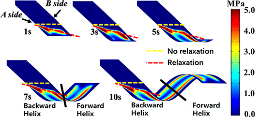
Figure 14. The process of CORC cabling (r= 3 mm, T= 100 MPa, 2w= 4 mm, t= 0.096 mm, α = 45°).
Download figure:
Standard image High-resolution image
Figure 15. The axial strain distribution of the REBCO layer in the helical wound tape (r = 3 mm, T = 100 MPa, 2w = 4 mm, t = 0.096 mm, α = 45°).
Download figure:
Standard image High-resolution imageThis is because the REBCO layer is below the strain neutral axis. The bending deformation causes a compressive strain, the pre-tension force results in a tensile strain, and the contact force is proportional to the winding pre-tension force. Therefore, combining equations (9) and (10) indicates that the greater the contact force in the area, the larger the tensile axial strain, but the overall level of axial strain decreases within this practical range of stress.
A test is performed to analyze the helical winding process and the traces of the contact between the tape and the former; the result is shown in figure 16. The experimental procedure starts with wrapping the core with white paper and covering the tape's inside with paint. After completing the helical winding process, the pressed white paper with paint shows relaxation only at the B-side, which agrees with the FEM result. In summary, the relaxation and Poisson effects, both occurring during the helical winding process, can be described well by the given models.
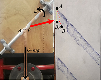
Figure 16. Relaxation in natural helical winding.
Download figure:
Standard image High-resolution image4.2.1. Winding pre-tension force.
The contact force distribution between the tape and the core is directly related to the imposed winding pre-tension force in the helical winding process (see figure 17). First, as the winding pre-tension force increases, the contact force between the tape and the core increases, which agrees with the results calculated by equation (26). Second, during the helical winding process, the winding pre-tension force does not affect the 'ear' lifting length as resulted from equation (19). Furthermore, because of the helical winding, the tape's relaxation condition is different on both sides. The A-side's contact force is higher than that of the B side in the forward helix, while it is the opposite in the backward helix.

Figure 17. (a) The contact stress distribution after helical winding with different winding pre-tension force. (b) The contact stress distribution along the tape width in the forward helix (r = 3 mm, 2w = 4 mm, t = 0.096 mm, α = 45°).
Download figure:
Standard image High-resolution image4.2.2. Winding helix angle.
The helix angle also has a significant influence on the contact stress, and the results of these calculations are shown in figure 18. As the winding helix angle increases, the contact force between the tape and the core decreases. When the helix angle is 0°, corresponding to the pancake winding, the A-side and the B-side will relax simultaneously, while the relaxation only occurs on the B-side at other angles. Moreover, as the angle increases, the relaxation on the B-side also increases. As the winding angle increases, the 'ear' lifting length also gradually decreases until the angle becomes larger than 60°. The contact stress distribution, along with the tape width, changes from contact type II (between 0°and 35°) to contact type I (larger than 55°), which is confirmed by the results from equation (19).

Figure 18. (a) The contact stress distribution after helical winding with different helix angle. (b) The detail contact stress distribution along the tape width in the forward helix ( = 3 mm, T = 100 MPa, 2
 = 4 mm,
  = 0.096 mm).
Download figure:
Standard image High-resolution image4.2.3. Radius of winding core.
Like the other geometrical parameters, the core radius of a CORC also significantly affects the contact stress (figure 19). As the core radius increases, the contact force between the tape and the core decreases. It is also observed that the A-side's contact force is greater in the forward helix than that at the B-side. However, when the core radius is reduced to 1.5 mm, at the same position, the A-side's contact force becomes less than that at the B-side. This is because the stress concentration at the red dashed line position in figure 19(a) causes a gap between the tape and the core. As the core radius increases, the relaxation effect gradually weakens. It can be seen from the yellow and red dashed lines' relative position in figure 19(a). The 'ear' lifting length also increases as the core radius increases.
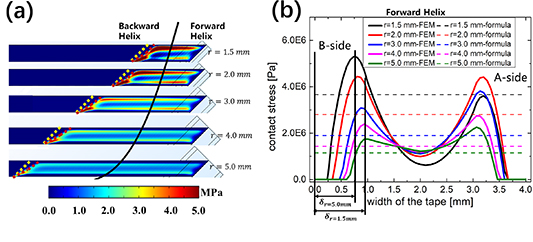
Figure 19. (a) The contact stress distribution after helical winding for different core radii. (b) The detailed contact stress distribution along the tape width in the forward helix (T= 100 MPa, 2w= 4 mm, t= 0.096 mm, α = 45°).
Download figure:
Standard image High-resolution image4.3. Optimization of pancake coiling and CORC cabling
In engineering practice, the winding pre-tension force requires a suitable range. In equation (8),  is the axial force in the tape. When
  , obviously the tape cannot be tightly wound on the core, and causes winding failure (the tape is buckling). When the winding pre-tension force is taken too large, the axial strain in the REBCO layer can exceed the irreversibility strain limit
  and as a result, the tape's current transport performance will be degraded irreversibly. The minimum winding pre-tension force for pancake coils and CORC cables is
  . Figure 20 shows the winding pre-tension force of SCS4050 and SCS2030 for different winding radii. The yellow area represents 60%–95% of the critical current, and the orange area is more than 95% of the critical current after winding. Point A is the minimum winding radius limit. Point D is the minimum winding radius that retains 95% of the critical current transport performance. Although evident, the results show that SCS2030 tape can make smaller pancake coils and thinner CORC cables.

Figure 20. The SCS4050 and the SCS2030 tape allowable winding radius of curvature and pre-tension force diagram. The yellow area represents 60%–95% critical current after winding, and the orange area is larger than 95% critical current after winding.
Download figure:
Standard image High-resolution imageIn addition, we discuss the contact shape between the tape and the core after the winding process under different winding pre-tension forces and different winding factors. There are three shapes of contact (figure 6), identified as respectively: single-line contact (contact type I), double-line contact (contact type II) and surface contact (contact type III). These three different shapes are described by equations (22) and (23). For the winding process, the engineering concern is the winding pre-tension force  and winding factor
  . Therefore, substituting
  and
and ![$\bar \lambda = w\sqrt[4]{{\frac{{3\left( {1 - {\nu ^2}} \right)}}{{{\rho ^2}{t^2}}}}}$](https://content.cld.iop.org/journals/0953-2048/34/7/075003/revision3/sustabf710ieqn81.gif) into equations (22) and (23) results in:
into equations (22) and (23) results in:
Here, the parameters  and
and  are constants and only depend on the tape selection (see table 1). In this case, the contact shape diagram is obtained using the SCS2030 and SCS4050 tapes as examples; see figure 21. The black line is calculated by equation (27), the red line is obtained by equation (28) and the blue line is the minimum winding pre-tension force after considering the relaxation effect. The contact shape is also calculated by the FEM model, for both the SCS2030 tape (F = 0.9 or 2.7 N;
  = 3 or 30 mm) and the SCS4050 tape (F = 5 or 20 N;
  = 3 or 40 mm). The contact force distribution is consistent with the location of the black spot. Usually, the core radius of pancake coils is larger. When the winding curvature is larger than 15 mm (SCS2030) or 25 mm (SCS4050), the contact shape is either type II (at low tension) or type III (at high tension). For the CORC cable, the helical curvature radius is smaller. When the helical curvature radius is smaller than 10 mm, the contact shape is either type I (at low tension) or type III (at high tension).

Figure 21. The contact shape between the tape and the core during the winding process with different winding factors and forces.
Download figure:
Standard image High-resolution imageInteresting to note is the detailed contact behavior of SCS2030 and SCS4050 tapes after the winding process. It is worth mentioning that it is assumed in the calculations that the tape surfaces are flat and plane-parallel in the initial condition. However, the copper surface will have its specific roughness and profile in reality. In figure 22 the results are presented for the tape's contact stress distribution during pancake coiling (tape SCS2030 and SCS4050, r= 3 mm, 2w= 2 or 4 mm, t= 0.045, or 0.096 mm, α = 0°). The dotted lines are the calculation results of equation (26). The results show that the SCS2030 tape also undergoes the edge 'ear' lifting due to the Poisson effect. As previously noted, the contact force also increases as the pre-tension force increases. Compared to the SCS4050 tape, the contact force in the SCS2030 tape is small for the same winding parameters (pre-tension force, core radius, helix angle). The corresponding axial stress in the REBCO layer and the critical current degradation are also small. The 'ear' lifting length for the SCS2030 tape is shorter than for the SCS4050 tape. When the pre-tension force is 10 MPa, the core radius is 3 mm, and the helix angle is zero degrees, both contact shapes of SCS2030 and SCS4050 tapes are of type II, which is a double-line contact.

Figure 22. The contact stress between the tape and the core after the pancake coiling (a) SCS2030, (b) SCS4050 ( = 3 mm, 2
 = 2, 4 mm,
  = 0.045, 0.096 mm,
  = 0°).
Download figure:
Standard image High-resolution image
In summary, for both pancake coiling and CORC cabling, the relaxation and Poisson effects need to be considered throughout the above analyses. The non-linear contact behavior between the tape and the core is mainly described by the contact force and the edge 'ear' lifting length. Equation (26) approximates the average force. For a selected tape, the relation between contact shape, winding pre-tension force and core radius can be assessed from figure 21. The FEM model can accurately calculate the contact stress between the tape and the core during pancake coiling and CORC cabling. The calculation results indicate that the SCS2030 tape is indeed more flexible (thinner and narrower) than the SCS4050 tape and more suitable for making pancake coils and CORC cables.
5. Conclusion
The analytical and FEM models for winding REBCO tape considering both the relaxation and Poisson effect are established. Through the obtained models, the relaxation (relaxation offset distance, relaxation angle), the contact force, and the edge 'ear' lifting length are calculated for different winding parameters (pre-tension force, winding radius of curvature, helix angle). The theoretical model, the FEM model, and the test results are consistent. For a specified superconducting tape, the minimum pre-tension force to wind successfully has been defined. The critical current irreversibility strain limit determines the upper limit. The greater the winding pre-tension force, the smaller the helical curvature radius, and the greater the contact force. The specific profile shape of the contact between the tape and the core is consistent with the calculation by the FEM model. The contact behavior betweenthe tape and the core during the winding process calculated by the FEM model can provide a theoretical basis for the subsequent calculation of the electrical contact resistance for evaluation of AC loss and quench protection. These models can serve in the design optimization of pancake coils and CORC cables.
Acknowledgments
Funding: This work was supported by the National Natural Science Foundation of China (12072136), the China Scholarship Council award to Keyang Wang for 2 years' study abroad at the University of Twente (CSC201906180053), and the Bureau of Science and Technology of the City of Yichang (A18-302-a15).
Data availability statement
All data that support the findings of this study are included within the article (and any supplementary files).