

Abstract
In order to improve the environmental adaptability and interaction stability of industrial robotic arms, a flexible joint with variable damping and stiffness based on magnetorheological (MR) technology was proposed. The mechanical models for variable stiffness and damping of MR flexible joint were established, and the relationship between cam surface and variable stiffness element was derived based on the energy method. Subsequently, the variation patterns of equivalent stiffness and damping of the prototype under different excitations were experimentally tested, and the test results show that its mechanical properties meet the design requirements. To further verify the performance of the MR flexible joint on the robotic arm, we setup a collision buffering test system and investigated the buffering performance of the system under different working conditions. The buffering test results indicate that when the current of variable stiffness element is 2.0 A, the peak collision acceleration of the system after installing the MR flexible joint decreases by about 40.19% compare with the rigid collision.
Export citation and abstract BibTeX RIS
1. Introduction
Robots play an important role in current industrial production, as they can replace humans to complete tedious, dangerous, and repetitive tasks, greatly improving production efficiency and quality [1–3]. With the integration and innovation of information, material, manufacturing, integrated circuit and other technologies in recent decades, robot technology has been further developed [4–6]. Traditional robots require high joint stiffness to meet the requirements of high load and high repetitive positioning accuracy in industry [7], which results in a significant force even for a small position tracking error. When the robot collides due to external factors, it not only causes personal injury to the staffs, but also damages the body structure of the robot, reducing its service life. Therefore, robots need to introduce flexible joint to have a better environmental adaptability [8–10].
Although introducing a simple flexible structure can improve the environmental adaptability of robots to a certain extent, it will also lead to an increase in robot position tracking error and cause residual vibration at the end [11]. On the other hand, it will bring negative effects such as reduced bandwidth and dynamic performance of the robot. Therefore, Zinn et al [12] proposed the design concept of variable stiffness robots to adapt to the stiffness requirements of robots under different working conditions. Variable stiffness robots can adjust joint stiffness based on differences in task conditions to improve their environmental adaptability. When performing tasks that require high flexibility, such as picking up fragile objects, small joint stiffness can be used to reduce the force applied by the robotic arm and prevent damage to the object, while low stiffness can also help absorb shocks and prevent damage to the robot body, equipment, etc. When performing tasks that require fast movement, such as assembly line work, adjust the rigidity to maintain robotic arm stability with small tracking errors. Overall, the adjustable stiffness of robots helps to optimize their stability under different tasks, improve work efficiency, and enhance interaction stability [13, 14].
Magnetorheological (MR) devices, as intelligent controllable devices, have gradually become a research hotspot in the field of buffering and vibration reduction due to their real-time adjustable damping force, rapid dynamic response, and low energy consumption [15–19]. Compared with traditional damping devices, MR damping device have the characteristics of larger output damping force, strong adaptability and wide dynamic range. The working modes of MR damping devices mainly include shear mode and flow mode [20]. The former uses the rheological effect of MR fluid under the action of magnetic field to hinder the relative displacement between two walls, so that the damping effect occurs at the damping gap. The latter is to use the rheological effect of MR fluid to realize the adjustment of the pressure drop at both ends of the flow direction. Jiang et al [21] developed a robot leg based on MR technology, which mainly consists of a rotary MR damper, spring, and other structures. The adaptation of robot leg to different working environments is realized through the variable lever arm of MR damper and spring. The experimental results show that the robot leg have good adaptability when walking on relatively hard terrain, are easy to control, and have a simple structure. Dong et al [22] designed a rotary MR flexible joint with adjustable stiffness and damping to reduce the vibration caused by torque transmission. Through theoretical analysis and experimental verification of the mechanical properties of the joint, it has been shown that the stiffness and damping performance of the joint can be independently controlled, its equivalent stiffness and the damping coefficient can be adjusted between 5.15–12.28 Nm rad−1 and 0.83–3.6 kNs m−1, respectively. However, due to its large overall volume, it has significant limitations on the installation space. Christie et al [23] proposed a variable stiffness leg using MR elastomeric joint in an inverted pendulum morphology. The hybrid excitation method of permanent magnet and excitation coil was chosen to achieve stiffness adjustment, thus achieving semi-active control with a maximum stiffness change of 48%. Xu and Ahmadian [24] proposed an improved vehicle suspension system with variable stiffness and damping, and studied the impact of suspension on vehicle driving performance. Based on the suspension with variable stiffness and damping, a corresponding fuzzy control algorithm was proposed. Simulation results show that the suspension with variable stiffness and damping can enhance the normal force of wheels and improve the driving stability of vehicles [25–27].
At present, there is still significant room for improvement of flexible joints with variable stiffness based on MR technology. Most studies are based on the squeezing of MR elastomer to achieve variable stiffness effect, so the overall size of flexible joints is relatively large, which is not conducive to its widespread application. Therefore, it is necessary to propose a compact robot joint with variable stiffness and damping to improve the performance of the robot, increase its adaptability and flexibility to the environment, and ensure the reliability of the robot at work.
This paper presents a MR flexible joint with compact structure, low energy consumption, and controllable stiffness and damping for the collision vibration reduction of industrial robotic arm. The variable stiffness technology, which converts radial stiffness into circumferential stiffness through a cam mechanism, is effective and reliable. By analyzing and deriving the variable stiffness theoretical model of the joint, key design parameters are obtained and the joint prototype is fabricated. The mechanical performance of the prototype is tested using the established experimental platform, thereby verifying the effectiveness and rationality of the theoretical design. Finally, the collision buffering test system for the robotic arm is setup, and the impact of damping and stiffness of the flexible joint on the collision buffering performance of the robotic arm is analyzed experimentally.
2. Structural concept
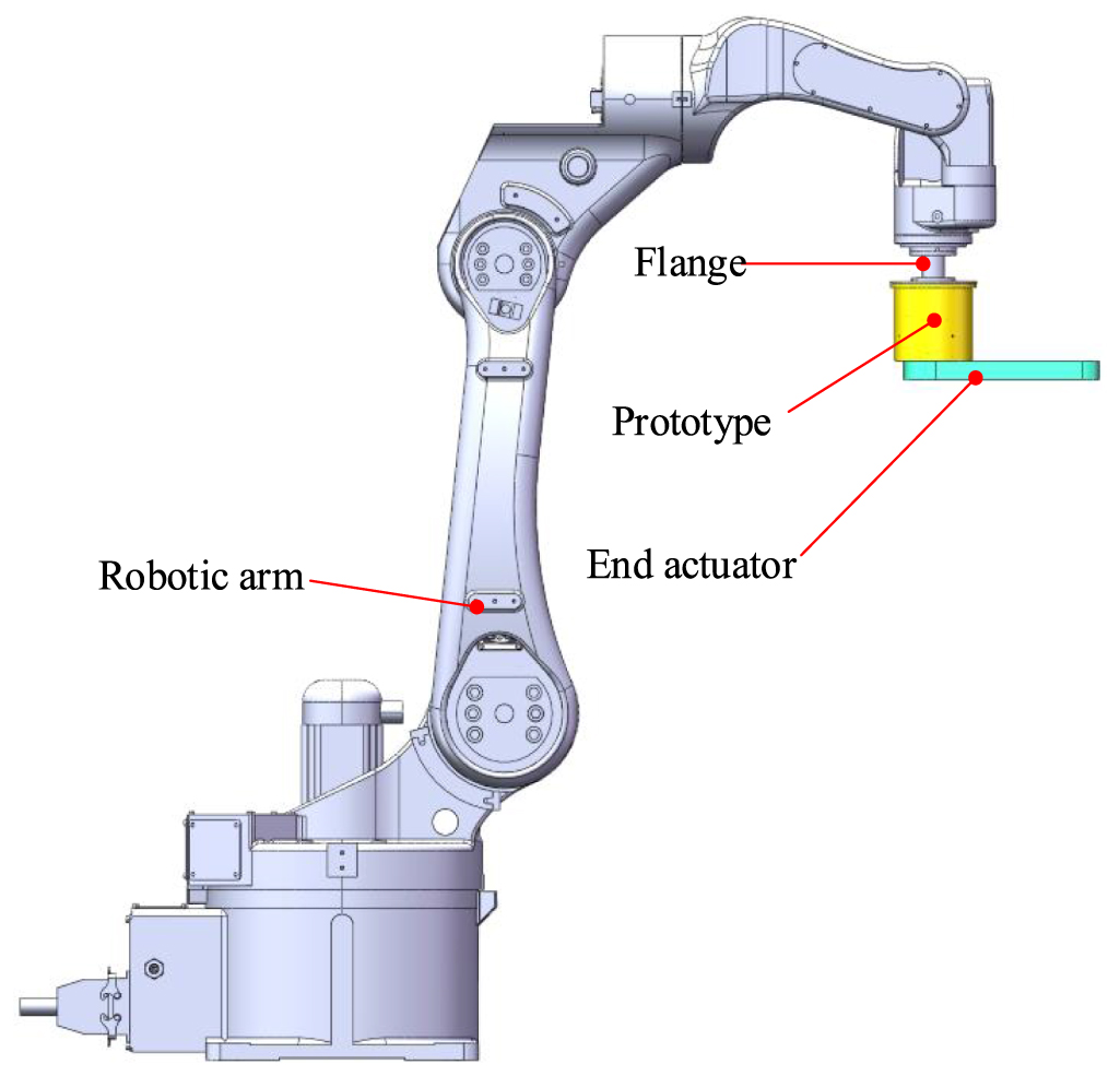
As shown in figure 1, the MR flexible joint proposed in this paper, as a connecting part between the end of the robotic arm and the actuator, should be simple, compact, and easy to disassemble and repair. In order to be able to connect with existing industrial robot, its external dimensions should not exceed 110 mm, and it does not affect the existing structure and motion range of the robotic arm. Considering the limited load of the robot, the weight of the joint should not exceed 3.5 kg, lightweight materials should be used and the components should be designed with lightweight when the strength meets the working conditions. Meanwhile, to meet the working requirements of the robot and improve its environmental adaptability, the maximum output torque of the flexible joint needs to be above 8 Nm.
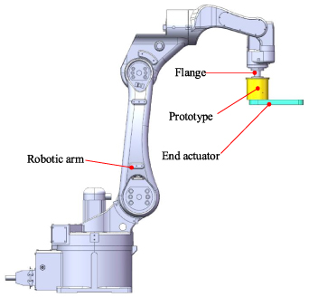
Figure 1. The installation position of MR flexible joint.
Download figure:
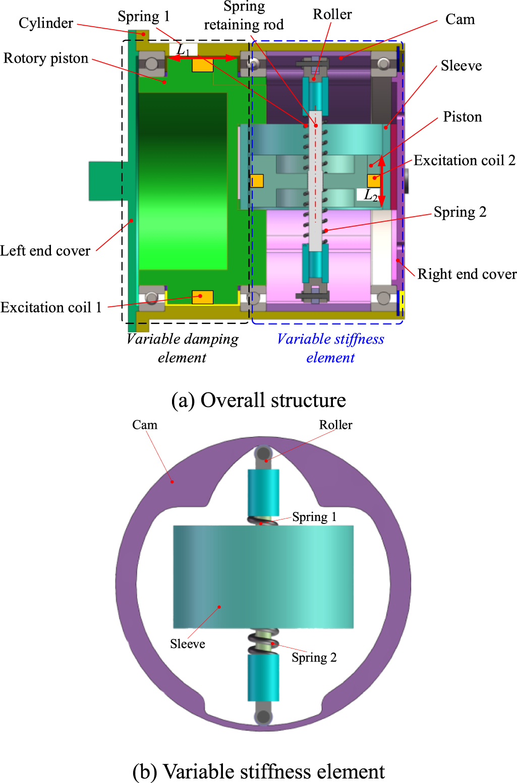
Standard image High-resolution imageThe MR flexible joint proposed in this paper is composed of a variable stiffness element and a variable damping element. The variable damping element adopts a conventional shear mode of MR material, but the MR material is selected the MR composite developed by Li et al [28]. Compared with the MR fluid, MR composite have greater shear yield stress under same volume and do not require special sealing structures, which can reduce the size of MR device. The variable stiffness element adopts a combination structure of a linear MR damper under shear mode, two spiral springs, and a cam. Based on the adjustable damping characteristics of MR material, the variable stiffness element has a simple structure, low energy consumption, and a more compact connection with the variable damping element. The structural diagram of the MR flexible joint is shown in figure 2.

Figure 2. Structure diagram of MR flexible joint.
Download figure:
Standard image High-resolution imageThe joint mainly consists of the end cover, rotary piston, cylinder, spring retaining rod, excitation coil, spring, roller, cam, sleeve, and piston.
- (1)Variable damping principle: The cylinder and end cover of the joint serve as the torque output part, and the cylinder also serves as the sleeve of the variable damping element, which reduces the complexity of the structure. The rotary piston utilizes two bearings in the cylinder to achieve positioning and ensure their coaxiality to improve output stability. The working area between the rotary piston and the cylinder is filled with MR composite, which can eliminate sealing components, simplify joint structure, and avoid the influence of the friction caused by sealing rings on the dynamic range of stiffness. When the excitation coil 1 is energized, the magnetic field is generated in the working area of the variable damping element (L1 is the length of the effective working gap). The apparent viscosity of the MR composite can be changed by adjusting the excitation current, thereby controlling the equivalent output damping of the flexible joint.
- (2)Variable stiffness principle: The variable stiffness element is composed of the MR variable stiffness mechanism, roller, and cam. The MR variable stiffness mechanism can be equivalent to a variable stiffness spring controlled by current, which is consisted of a linear MR damper (Piston, sleeve, and excitation coil 2), a spring retaining rod, and two spiral springs. The cam converts the rotational motion of the variable stiffness element into the linear motion of the roller along the spring retaining rod, compressing the MR variable stiffness mechanism to generate force, and it generates torque through the reaction force of the roller on the cam. As shown in figure 2(b), the damping force of the linear MR damper (the piston in the illustrated position is at the limit position) is controlled by the excitation coil 2 to adjust the condition of the spring 1 and 2, the stiffness of the MR variable stiffness mechanism is changed, thus changing the equivalent output stiffness of the joint (L2 is the length of the effective working gap). In addition, the parameters of the cam working surface can be designed according to the specific working conditions, so as to achieve the stiffness change characteristics under different angular displacements. The sleeve of the variable stiffness element is placed in the rotary piston groove of the variable damping element, which not only achieves parallel connection between the two elements, improves the torque output ability of the joint, but also makes the structure more compact.
3. Mechanical model
3.1. Variable damping of the proposed joint
The output torque of variable damping element is mainly affected by the magnetic induced yield stress of MR composite, that is, the magnetic field intensity in the effective damping gap and the rheological properties of MR composite directly affect the performance of variable damping element. If the complex working conditions of MR composite are considered, the difficulty of deriving the mechanical model of variable damping element will be greatly increased. Therefore, the derivation of variable damping principle in this paper is based on the following assumptions:
The MR composite is uniformly distributed in the damping gap, which is not affected by joint rotation and gravity, and the rheological properties of the material are not affected by temperature. Also, the direction and magnitude of the magnetic field in the damping gap are consistent, without considering the non-uniformity of the magnetic field in the gap and the influence of component rotation.
The schematic diagram of the variable damping element is shown in figure 3, and the working area is composed of the gap between the cylinder and the rotary piston. r1 is the outer diameter of the rotary piston, and r2 is the inner diameter of the cylinder.
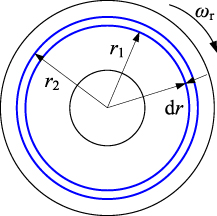
Figure 3. Schematic diagram of variable damping.
Download figure:
Standard image High-resolution imageAccording to the previous study [29], the output torque Mc of the variable damping element with the working radius of r can be:
3.2. Variable stiffness of the proposed joint
3.2.1. Design theory.
The original model and equivalent model of the variable stiffness element in the proposed MR flexible joint are shown in figure 4. In figures 4(a), m is the roller mass, x is the input displacement of the variable stiffness element, x2 is the input displacement of the spring-damper parallel node, x1 is the output displacement of the variable stiffness element, k1 and k2 are the tensile and compressive stiffness of the springs, and c is the damping coefficient of the linear MR damper. In figure 4(b), cs and ks are the equivalent damping and equivalent stiffness of the variable stiffness element, respectively. As shown in the figure, the spring (k2) is connected in parallel with the linear MR damper (c) and then connected in series with the spring (k1).

Figure 4. Model of the variable stiffness element.
Download figure:
Standard image High-resolution imageAccording to Newton's second law of motion, the dynamic model of the original model can be obtained as follows:
The equivalent dynamic model is:

where,  and
and  are the input velocity and the input acceleration of the variable stiffness element, respectively.
  is the input velocity of the spring-damper parallel node, and
  is the output velocity of the variable stiffness element.
Applying Laplace transform to equations (2) and (3) to obtain:
By bringing s= jω into equations (4) and (5), we get:
The original model and the equivalent model describe the same system, so the transfer function is consistent. Therefore, by comparing the terms in equations (6) and (7), it can be concluded that:
3.2.2. Variable stiffness model.
The spring pressure of the variable stiffness element is converted to the output torque of the joint through the cam. The joint rotation drives the cam rotation to force the roller to compress the spring, the radial stiffness is converted to the circumferential stiffness, and the output torque Ms of the element is the product of the spring reaction force on the cam surface and the distance from the action point to the joint rotation center. Figure 5 shows the simplified diagram of the output torque of the MR flexible joint variable stiffness element, and the relationship between the output torque and the structure is derived through force analysis.

Figure 5. Simplified diagram of variable stiffness element.
Download figure:
Standard image High-resolution imageDue to the balanced force on the roller, according to Newton's second theorem, it can be obtained that:

where, F is the force exerted by the cam on the roller, β is the angle between the normal of the cam curve at the tangent point and the spring axis, Fk is the spring force, Δx is the compression displacement of spring.
Obtained joint output torque Ms:


where, θ is the rotation angle of the spring retaining rod, ϕ is the angle between the contour normal at the tangent point and the x-axis, ρ(θ) is the polar diameter (the expression of the contour curve in polar coordinates), which is the arm of force.
According to equations (10) and (11), it can be obtained:
where, kf is the slope of cam contour normal, kf = tanϕ:
where, x and y are the expression of the cam curve in Cartesian coordinates.
Based on the in the above theoretical analysis, the total output torque M of the MR flexible joint can be obtained as follows:

3.2.3. Design of the cam working surface.
From the above analysis, the design of the cam working surface involves the deformation of the spring and the size of the force arm. If the angle of the contour surface changes nonlinearly, the equivalent output stiffness of the MR flexible joint can also change nonlinearly, thus affecting the variable stiffness performance. Within a certain range, only fixed stiffness springs can be used, and various required stiffness changes can be obtained based on different cam working surfaces. Therefore, the design of cam contour surfaces is very important for the performance of MR flexible joint.
The energy conservation method was used to obtain the cam curve. If the torque Ms rotates the variable stiffness element so that its rotation angle is θ, the elastic potential energy Ep(θ) stored by the spring under pressure is:
where ρ(0) is the pole diameter of the initial position.
In this case, the work Wp(θ) done by torque Ms is:

Without considering the energy loss caused by friction, etc., the work done by the torque is equal to the elastic potential energy stored by the system, and the combined equations (15) and (16) can be obtained:

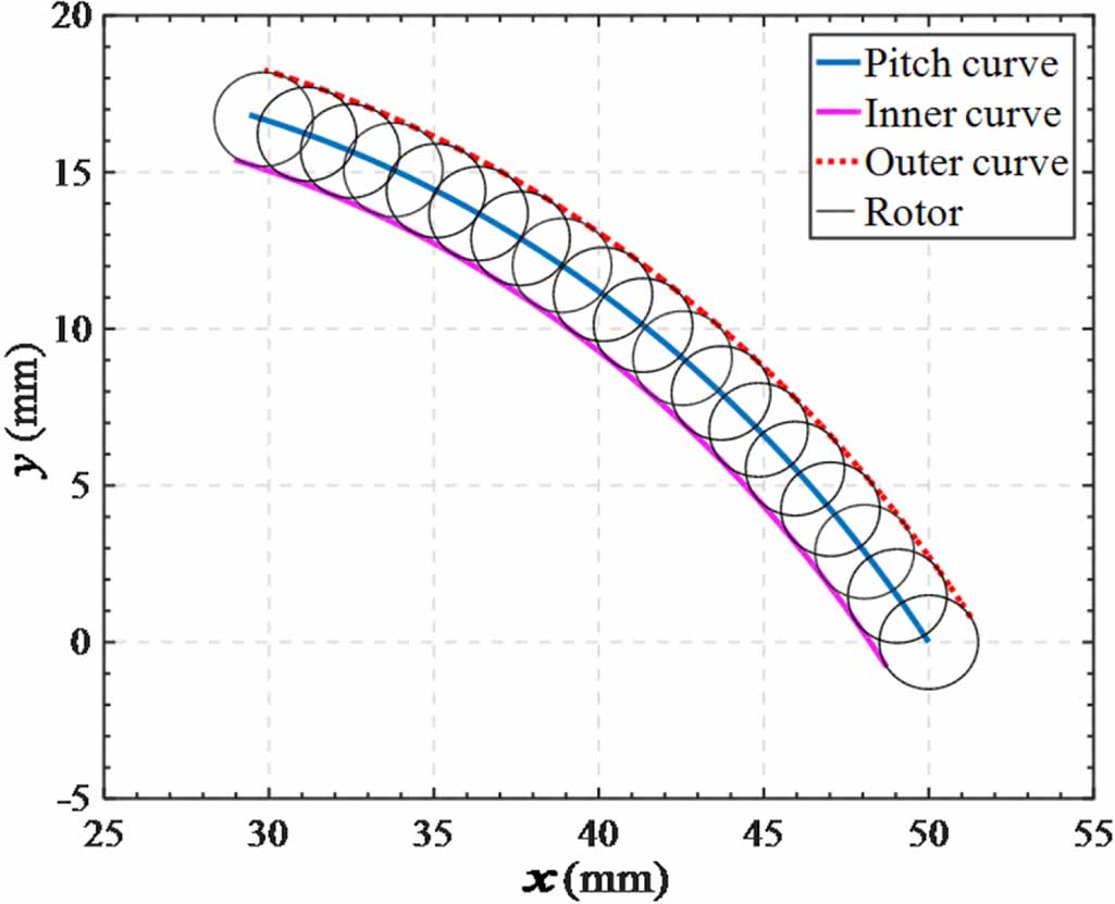
From equation (17), the cam working surface can be determined based on the expected output torque function and spring stiffness, and the above derivation results in a theoretical working surface. To obtain the actual working surface, it is necessary to consider the influence of roller radius on the contact point. In the Cartesian coordinate system, the pitch curve is:
The actual cam curve of the cam shown in figure 6 can be obtained:
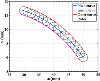
Figure 6. Curve of cam.
Download figure:
Standard image High-resolution imagewhere, R is the radius of the cam base circle,  .
.
Combined with equation (12), can be obtained:

where, ke is the equivalent stiffness of the MR variable stiffness mechanism.
Equation (21) indicates that the equivalent stiffness of the MR flexible joint is related to the parameters of the cam working surface and the stiffness of the MR variable stiffness mechanism, and verifying the feasibility of the proposed variable stiffness structure.
3.2.4. Dynamic simulation of the variable stiffness element.
Adjusting the damping coefficient of the linear MR damper can change the output stiffness of the MR variable stiffness mechanism, and the equivalent output stiffness of the variable stiffness element can be controlled through the motion conversion by the cam mechanism. To verify the correctness of the above theoretical derivation, an equivalent multi body dynamic model of the variable stiffness element was established using ADAMS. Given different damping coefficients, the equivalent stiffness ks of the MR variable stiffness mechanism, the torque Ms and the equivalent stiffness ke of the variable stiffness element were simulated and calculated. ADAMS virtual prototype is shown in figure 7, its key parameters are shown in table 1, and simulation results are shown in figures 8–10.
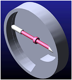
Figure 7. ADAMS virtual prototype.
Download figure:
Standard image High-resolution image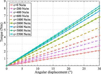
Figure 8. Variation of output torque with damping coefficient.
Download figure:
Standard image High-resolution image
Figure 9. Equivalent stiffness of MR flexible joint varies with damping coefficient.
Download figure:
Standard image High-resolution image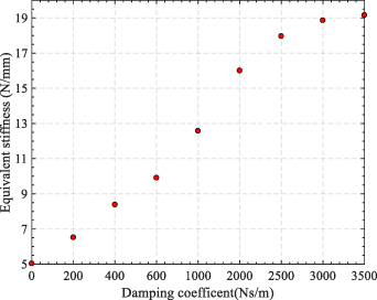
Figure 10. Equivalent stiffness of MR variable stiffness mechanism varies with damping coefficient.
Download figure:
Standard image High-resolution imageTable 1. Parameters of virtual prototype of variable stiffness element.
| Symbols | Variables | Values |
|---|---|---|
| k1 | Stiffness of the spring 1 | 20 (N mm−1) |
| k2 | Stiffness of the spring 2 | 5 (N mm−1) |
| c | Damping coefficient of linear MR damper | 0–3500 (Ns m−1) |
As shown in figure 8, the output torque of the MR flexible joint without considering the variable damping element can be linearly output according to the design while the damping coefficient of the linear MR damper remains unchanged, indicating that the theoretical derivation of the cam working curve is correct. When the damping coefficient of the variable stiffness element is increased at the same rotation angle of the joint, the output torque increases, that is, the joint equivalent stiffness increases.
As shown in figure 9, the joint equivalent stiffness and the damping coefficient have a nonlinear relationship, and the influence of continued increase of damping on the output torque tends to be gentle when the damping coefficient exceeds a certain value. Analyzing figure 10, the variation range of equivalent stiffness ks of the MR variable stiffness mechanism is between  , which is consistent with the theoretical derivation conclusion. The above simulation results verify the structural feasibility of the proposed MR flexible joint with variable stiffness and damping.
4. Performance test of prototype
4.1. Prototype and experimental platforms
Based on the overall structural design and principle analysis, the prototype of the MR flexible joint shown in figure 11 was fabricated.
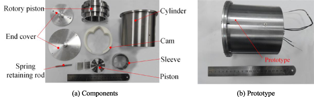
Figure 11. MR flexible joint prototype.
Download figure:
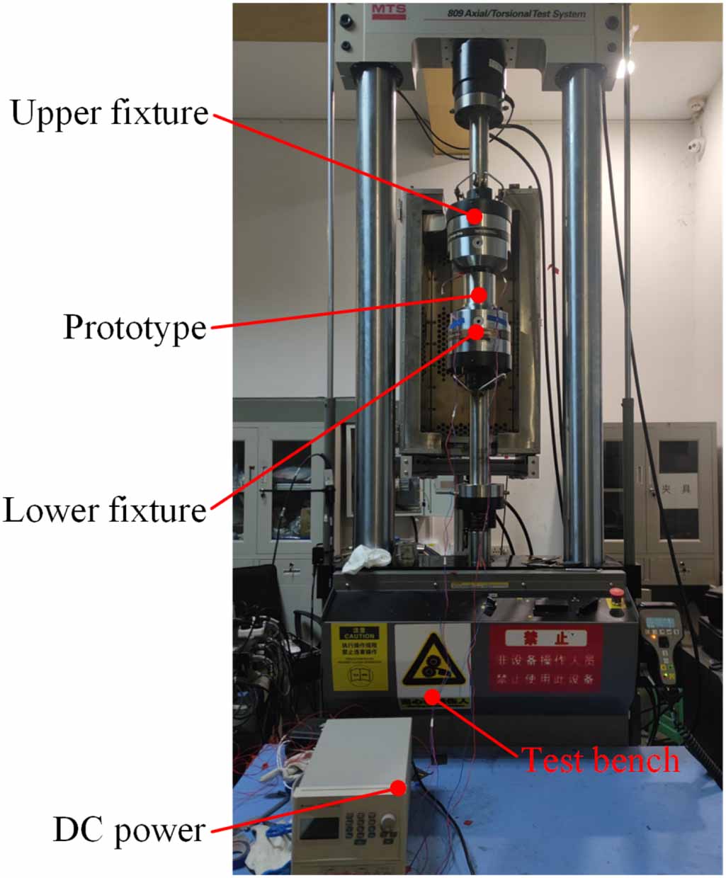
Standard image High-resolution imageFigure 12 shows the equivalent stiffness testing platform of the MR variable stiffness mechanism. The testing system consists of a computer, a DC power supply, a force sensor, upper and lower fixtures, a ZQ tensile machine, and the MR variable stiffness mechanism. The DC power supply provides excitation current to the linear MR damper to adjust the output of the system. And the testing of the variable stiffness and damping performance of the MR flexible joint was completed by the mechanical performance testing platform shown in figure 13. It is mainly composed of MTS tensile machine, DC power supply, PC, and the MR flexible joint prototype. The MTS tensile machine was used for clamping the MR flexible joint, providing excitation at different frequencies and rotation angles, and collecting real-time data such as torque and angular displacement during the testing process. DC power supply was used to regulate the excitation current of the excitation coil and adjust the output performance of the MR flexible joint.

Figure 12. Test platform for MR stiffness mechanism.
Download figure:
Standard image High-resolution image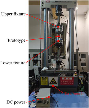
Figure 13. Test system for MR flexible joint.
Download figure:
Standard image High-resolution image4.2. Equivalent stiffness characteristics of the MR variable stiffness mechanism
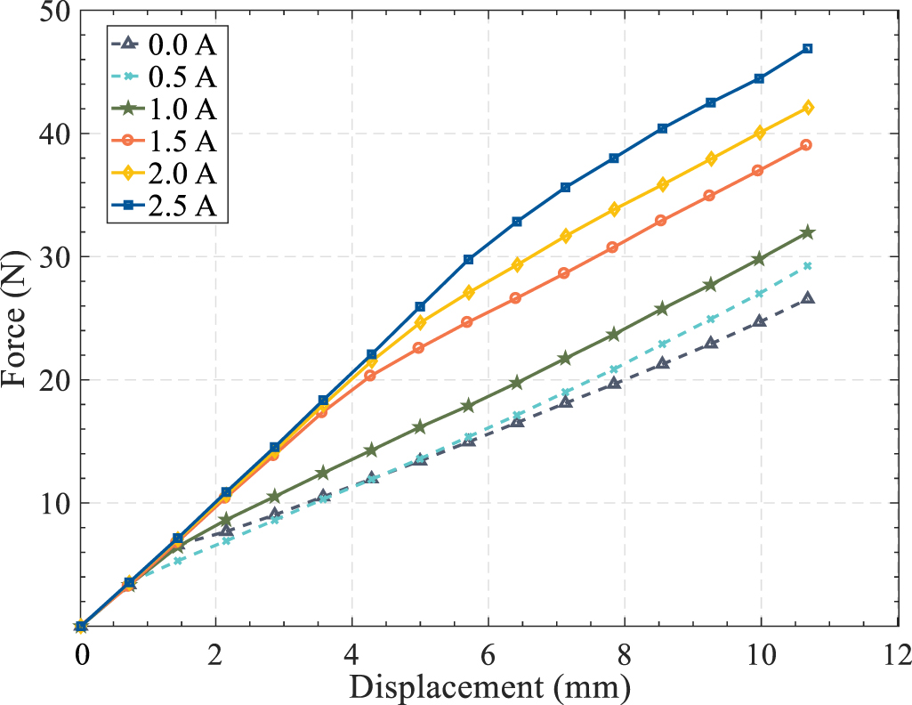
The equivalent stiffness was tested using the test platform in figure 12. The compression displacement of the tensile machine was set as 11 mm, and the curve of equivalent output stiffness with displacement of the MR variable stiffness mechanism is shown in figure 13. By analyzing figure 14, the output force of the MR variable stiffness mechanism increases with the increase of current under the same compression conditions, indicating that increasing the excitation current can effectively improve the output stiffness of the structure, and its equivalent stiffness has a good controllability. The force versus displacement curve of the MR variable stiffness mechanism changes smoothly, which is basically consistent with the trend shown by Hooke's law. This indicates that the output stiffness characteristics of the MR variable stiffness mechanism are like those of the springs, and proving the good stability of the working performance of the MR variable stiffness mechanism.
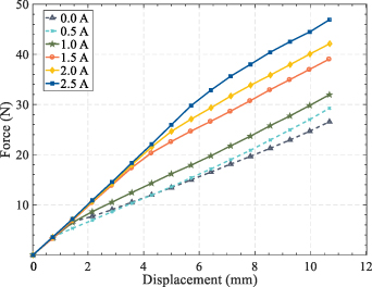
Figure 14. Force versus displacement of MR variable stiffness mechanism (20 mm min−1).
Download figure:
Standard image High-resolution imageFigure 15 shows the results of equivalent stiffness of the MR variable stiffness mechanism with the current at different compression speeds, and the equivalent stiffness of the mechanism increases with the increase of current. At the initial part of the force-displacement curve, its slope is relatively large, approximately equal to the stiffness value k1 of the spring, and this part will be extended with the increase of the excitation current. Further analysis that this is because the piston movement driven by the tensile machine needs to overcome the damping force of the linear MR damper, and the damping force increases with the increase of current. Before the piston movement, only the spring k1 working, therefore the output stiffness at the initial part is relatively high, and the excitation current affects the length of this part. In general, the output force of the mechanism is smooth, and the performance of the MR variable stiffness mechanism is stable. In addition, increasing the compression speed can improve the output force, but to a lesser extent. The equivalent output stiffness is 2.57 N mm−1 at the current of 0 A, the equivalent output stiffness is increased to 4.69 N mm−1 when the current is increased to 2.5 A, and the dynamic range of stiffness is 1.82 (at 100 mm min−1). Through the above analysis, it can be concluded that the mechanism has good controllability of stiffness.
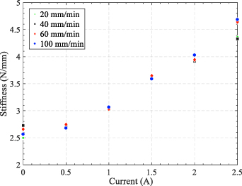
Figure 15. Equivalent output stiffness versus current of MR variable stiffness mechanism.
Download figure:
Standard image High-resolution image4.3. Stiffness characteristics of the proposed joint
The MTS test system shown in figure 13 was used to test the variable stiffness performance of the MR flexible joint. After low-pass filtering and visualization processing, the obtained test data showed the performance curve as shown in figure 16. The variable stiffness testing curve has a large DC component, which is due to the parallel connection between the variable stiffness element and the variable damping element, and the torque bias is caused by the damping torque.

Figure 16. Variable stiffness test results.
Download figure:
Standard image High-resolution imageIn addition, there is a certain fluctuation in the initial stage of the joint rotation, which is due to the inevitable gap between the piston and the sleeve of the linear MR damper, although filled with MR composite. Therefore, the subsequent analysis was based on a stable stage of 10–20°, and the processing results are shown in figure 17.
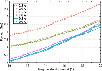
Figure 17. Variable stiffness in stable stage (0.4 Hz).
Download figure:
Standard image High-resolution imageIt can be seen from figure that under the same excitation frequency, increasing the excitation current of the variable stiffness element can effectively increase the output torque of the joint. In addition, the torque changes gently with the angle at the stage of 10–20°, indicating that the joint has a good torque ability. When the current is 0 A and 2.5 A, the equivalent output stiffness of the joint is 0.10 Nm rad−1 and 0.22 Nm rad−1 at 0.4 Hz, respectively. The dynamic range of the equivalent stiffness is about 2.2, indicating that the MR flexible joint has good controllability of the equivalent stiffness and variable stiffness ability, which meets the design requirements.
4.4. Damping characteristics of the proposed joint
To verify the effectiveness of the variable damping element, the output performance of the MR flexible joint was tested at different frequencies, amplitudes, and currents.
From figure 18, when the rotational amplitude is the same, increasing the excitation current can effectively increase the output torque of the MR flexible joint. The area enclosed by the curve in the figure increases with the increase of current, indicating that its energy dissipation ability increases. That is, by changing the excitation current, the damping output characteristics of the MR flexible joint can be well controlled, reflecting its good controllability. When the MR flexible joint changes direction of rotation, its output torque sinks inward, mainly due to the presence of a cavity in the variable damping element, and the formation of an empty stroke between the piston and sleeve at the reversing position. When the current increases from 0 A to 1.5 A, the torque increases more with the current than when the current increases from 1.5 A to 2.5 A, showing that the magnetic field of the variable damping element is gradually saturated. If the current continues to increase, the output torque will increase, but the increase amplitude will further decrease until the magnetic field is completely saturated.
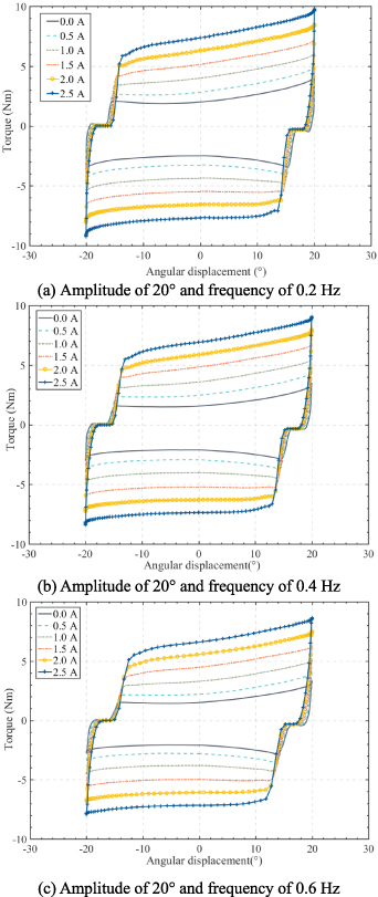
Figure 18. Torque-angular displacement of variable damping element.
Download figure:
Standard image High-resolution imageTaking figure 18(b) as an example, when the current is 0 A and 2.5 A, the maximum output torque is 3.98 Nm and 9.11 Nm, respectively. According to the damping coefficient calculation formula:
where, E is the area enclosed by the torque versus angle displacement curve in a period, f is the excitation frequency, and A is the excitation amplitude.
It can be obtained that the damping coefficient at 0 A and 2.5 A are 2.60 Nm (rad s−1)‒1 and 8.56 Nm (rad s−1)‒1, respectively, and the dynamic range of damping coefficient is 3.29. And according to the data obtained from the experiment, the equivalent damping coefficient of the MR flexible joint changes with the current was fitted by polynomial, as shown in figure 19.
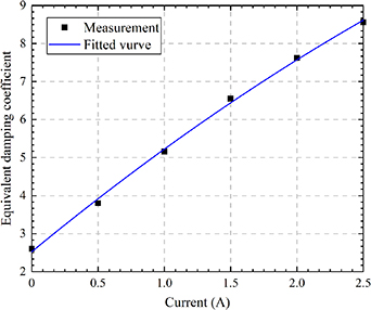
Figure 19. Variation of equivalent damping coefficient with currents.
Download figure:
Standard image High-resolution image5. Collision buffering test
5.1. Test system
In order to verify that the proposed MR flexible joint can effectively reduce the collision acceleration to protect workers and the robot body when the robot colliding with the external factors, the collision buffering test system of the robotic arm was setup as shown in figure 20. The test system mainly consists of DC power supply, PC, robotic arm, B&K acceleration sensor, dSPACE, sensor power amplifier and the MR flexible joint. By controlling the excitation current of the variable stiffness and damping elements of the MR flexible joint in the collision buffering system, the output characteristics of the joint prototype were adjusted. The B&K acceleration sensor was used to measure the vibration acceleration value during the collision process, and the sensor power amplifier can provide power to the acceleration sensor while amplifying electrical signals for data collection. PC and dSPACE together constitute a data acquisition system to collect and store the measurement data of the acceleration sensor and perform data post-processing.
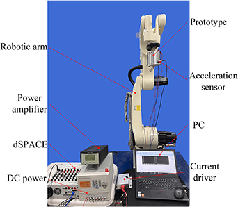
Figure 20. The collision buffering test system of the MR flexible joint.
Download figure:
Standard image High-resolution imageThe left end cover of the MR flexible joint was fixedly connected to the end of the robotic arm through a flange, and the acceleration sensor was connected to the right end cover through a mounting rod. At the same time, the mounting rod simulates the collision between the end actuator of the robotic arm and the outside factors. During the collision test, the end of the JH-605 robotic arm was controlled by the teaching box to move in a straight line, and the MR flexible joint moves together. When the operating speed of the robotic arm stabilizes, the mounting rod collides with a specific collision rod. Since the robotic arm has no additional buffering device besides its own structural buffering, the vibration of the robotic arm without the proposed joint is used as the control group in the test.
5.2. Analysis of collision buffering test results
The MR flexible joint collision buffering test consists of two parts: (1) the collision buffering test of the robotic arm under different equivalent damping: Analyzing the influence of joint damping on the collision buffering performance of the robotic arm. During the test process, the excitation current of the variable damping element is 0 A, 1 A, 2 A, and the excitation current of the variable stiffness element is fixed at 0 A. (2) The collision buffering test of robotic arm under different equivalent stiffness: Analyzing the influence of joint stiffness on the collision buffering performance of the robotic arm. During the test process, the excitation current of the variable stiffness element is 0 A, 1 A, 2 A, and the excitation current of the variable damping element is fixed at 0 A.
Capture the test data of 0.1 s before and after the collision, as shown in figure 21, showing the collision acceleration of the robotic arm under different equivalent damping. From the figure, the peak collision acceleration of rigid collision is 37.87 m s−2 without the MR flexible joint. After the MR flexible joint prototype is installed, the peak collision acceleration significantly decreases, and the peak collision acceleration increases from 10.26 m s−2 to 18.25 m s−2 when the current increases from 0 A to 2 A. The peak optimization rate of vibration acceleration is 51.81% compared with that of rigid collision at the applied current of 2 A. According to the data in figure 21, the peak collision acceleration of the robotic arm increases with the excitation current of the variable damping element, indicating that the output damping of the MR flexible joint will affect the collision buffering performance. The larger the damping coefficient of MR flexible joint, the larger the vibration acceleration during collision. When the damping coefficient is smaller, the frequency of oscillation will be increase and the time of vibration convergence will be extended. Figure 22 shows the power spectral density of the collision acceleration, and the collision energy is mainly concentrated around 75 Hz. Adjusting the damping of the joint can effectively absorb the collision energy, while increasing the damping will reduce the absorbed energy, because increasing the damping will lead to shorter buffering stroke and lower the energy consumption ability of the MR flexible joint.
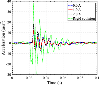
Figure 21. Collision acceleration under different equivalent damping.
Download figure:
Standard image High-resolution image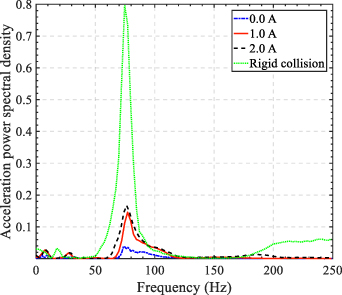
Figure 22. Power spectral density of collision acceleration under different equivalent damping.
Download figure:
Standard image High-resolution imageFigure 23 shows the collision acceleration of the robotic arm under different equivalent stiffness conditions. As show in the figure, the peak collision acceleration increases with the excitation current of the variable stiffness element. When the excitation current increases from 0 A to 2 A, the peak collision acceleration increases from 10.26 m s−2 to 22.65 m s−2. Under the condition of excitation current of 2 A, the optimization rate of the peak collision acceleration is 40.19% compared with rigid collision. Further analysis shows that the greater the equivalent stiffness of the MR flexible joint, the greater the acceleration during collision. At the same time, the greater the equivalent output stiffness of the joint, the longer the collision convergence time after impact. Compared with the peak collision acceleration data under different damping in figure 22, it was found that changing the equivalent output stiffness of the joint has a greater impact on collision buffering performance. Figure 24 shows the collision acceleration power spectral density under different stiffness. It can be seen from the figure that the collision energy of the joint will rapidly increase with the increase of stiffness, because small position deviation will cause large torque under the condition of high stiffness.
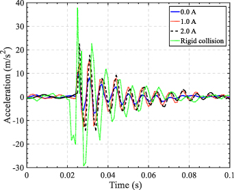
Figure 23. Collision acceleration under different equivalent stiffness.
Download figure:
Standard image High-resolution image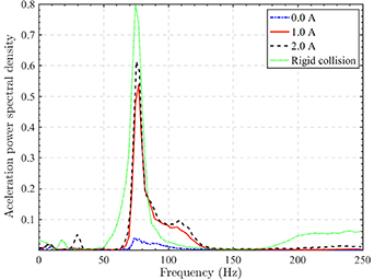
Figure 24. Power spectral density of collision acceleration under different equivalent stiffness.
Download figure:
Standard image High-resolution imageIn this paper, the head injury criterion (HIC) [30] was used to evaluate the safety of collision between the end actuator and the external factors. The lower the HIC value, the lower the damage degree of the impact on the actuator. The HIC equation is as follows:
where, t1 and t2 are the start and end time of evaluation respectively, a is the collision acceleration, and g is the gravitational acceleration.
According to equation (23), reducing the degree of human-machine impact injury (HIC value) can be achieved by reducing the contact stiffness of the collision position, reducing the effective mass (inertia) of the robotic arm, and reducing the operating speed of the robotic arm. In structural design, reducing the effective stiffness in the transmission chain is an effective measure to improve the safety of the robotic arm. The results obtained by calculating the HIC under various conditions in the collision buffering test of the robotic arm are shown in figure 25.
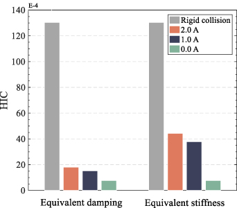
Figure 25. HIC of the collision buffering test system.
Download figure:
Standard image High-resolution imageIn the figure, after installing the joint prototype, the buffering effect of the robotic arm on collisions is more obvious. When a certain degree of collision occurs, it can improve the stability and safety of human-machine interaction (considering the reusability and safety of the robotic arm in the test, the collision force is set below 50 N). Compared to rigid collision, the lowest HIC value of vibration at the detecting point is about 7.7%. But for more intense collisions, the vibration effect that joint prototype can reduce in human-machine collisions is no longer significant. At this time, other measures need to be combined, such as adding additional buffer materials to reduce the stiffness of the collision position, algorithmic control of the operating speed, so as to better improve the safety of the robotic arm.
In order to further verify the vibration reduction effect of the proposed intelligent joint on the end actuator of the robotic arm, a simple closed-loop control experiment was conducted. Specifically, using the classic PID algorithm [31] to achieve real-time adjustment of joint damping and stiffness, and providing simple feedback on damping and stiffness through collected acceleration signals. Due to the limitations of experimental conditions and considering the disturbance of stiffness and damping adjustment signals during the experiment, closed-loop control was separately applied to the damping and stiffness element. And considering the time delay of the joint system, the vibration frequency of the collision is appropriately reduced and the duration of vibration is extended, so as to avoid the vibration time being too short to reflect the controllability of the algorithm.
Figure 26 shows the variation of acceleration amplitude and current when the damping element is controlled by PID (the current of variable stiffness element is 0 A). The excitation current is constantly adjusted according to the feedback of the acceleration amplitude, so as to suppress the vibration of the actuator. Due to the protection current set for the joint during the test, the maximum current during the initial vibration period is 2.5 A. As the acceleration amplitude decreases, the excitation current of the damping element also gradually decreases. The application of current is mainly in the early violent vibration, and the changing current is no longer applied to the small residual vibration in the later part. It can also be found from the figure that the change of current is slightly delayed due to the hysteresis of the joint system.
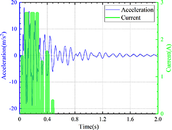
Figure 26. Collision acceleration and control current under PID control.
Download figure:
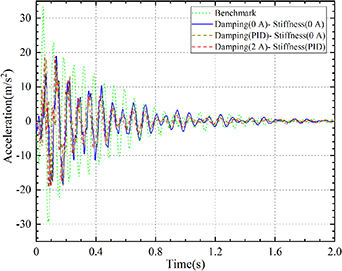
Standard image High-resolution imageFigure 27 shows the vibration acceleration curves under different conditions, which are the benchmark test without the joint (Benchmark), no excitation current of the joint (Damping(0 A)-Stiffness(0 A)), the damping element is controlled by PID/no current applied to the stiffness element (Damping(PID)-Stiffness(0 A)) (the stiffness should be small during collision), and apply 2 A current to the damping element/the stiffness element is controlled by PID (Damping(2 A)-Stiffness(PID)), respectively. In order to better demonstrate the effectiveness of the joint and control algorithm, the comparison curve of the benchmark test is added. Obviously, after the installation of flexible joints, the vibration of the end actuator is well suppressed, and the peak acceleration is reduced from about 33.25 m s−2 of the benchmark test to 18.05 m s−2. After applying PID closed-loop control to the damping and stiffness elements of the joint, the vibration suppression characteristics of the end actuator have been improved compared to the constant current tests in figures 21 and 23, especially in the later period of vibration, which can effectively shorten the residual vibration time.
Figure 27. Collision acceleration under different conditions.
Download figure:
Standard image High-resolution image
Based on the above analysis, the stiffness and damping of the MR flexible joint have a significant impact on the tracking accuracy of joint position and motor output torque. A large joint stiffness and appropriate joint damping can ensure a small tracking error while also requiring a small torque. After the robot stops moving, the residual vibration at the end of the robot can be effectively suppressed by selecting small joint stiffness and large joint damping, and the robot posture can be maintained with small torque of motor. When a collision occurs, small joint stiffness and damping can effectively reduce the acceleration of collision vibration. And compared with rigid collision, installing the MR flexible joint can significantly reduce human injury during collisions to a certain extent. In summary, the proposed MR flexible joint can adapt to the performance requirements of robot in different motion stages and working conditions by adjusting the stiffness and damping, thereby improving motion ability and interaction stability of the robot.
6. Conclusion
In order to meet the high requirements of interaction stability for industrial robots, a novel MR flexible joint with variable stiffness and damping was proposed and fabricated, in which the variable stiffness effect was achieved through a unique cam mechanism. Based on the derived mechanical models of MR flexible joint, the correctness of the variable stiffness and damping theories were verified.
The experimental platforms were used to test the performances of the MR flexible joint. The test results of the MR variable stiffness mechanism show that the maximum output stiffness is 4.69 N mm−1 and the dynamic range of stiffness is 1.82. The test results of joint equivalent stiffness and damping show that when the excitation current is 2.5 A, the equivalent stiffness is 0.22 Nm rad−1, the equivalent damping coefficient is 8.56 Nm (rad s−1)‒1, and the dynamic range of stiffness and damping are 2.2 and 3.29, respectively. The output performance of the MR flexible joint prototype is stable and it has good controllability. In addition, the results of the collision buffering test indicate that the interaction stability of the robotic arm can be effectively improved by MR flexible joint. Compared with the rigid collision of the robotic arm, the peak collision acceleration after installing the MR flexible joint is reduced by 40.19% at the current of 2.0 A (variable stiffness element).
Acknowledgments
This research is supported financially by the National Natural Science Foundation of People's Republic of China (52075056).
Data availability statement
All data that support the findings of this study are included within the article (and any supplementary files).
CRediT authorship contribution statement
Lifan Wu: Validation, Software, Writing-original draft, Writing-review & editing. Xiaomin Dong: Methodology, Supervision, Writing-review & editing, Funding acquisition. Baolin Yang: Conceptualization, Investigation, Validation.
Conflict of interest
The authors declare that they have no known competing financial interests or personal relationships that could have appeared to influence the work reported in this paper.